EP0348096B1 - Vehicle passenger seating - Google Patents
Vehicle passenger seating Download PDFInfo
- Publication number
- EP0348096B1 EP0348096B1 EP89306029A EP89306029A EP0348096B1 EP 0348096 B1 EP0348096 B1 EP 0348096B1 EP 89306029 A EP89306029 A EP 89306029A EP 89306029 A EP89306029 A EP 89306029A EP 0348096 B1 EP0348096 B1 EP 0348096B1
- Authority
- EP
- European Patent Office
- Prior art keywords
- seating unit
- armrest
- vehicle
- support frame
- recess
- Prior art date
- Legal status (The legal status is an assumption and is not a legal conclusion. Google has not performed a legal analysis and makes no representation as to the accuracy of the status listed.)
- Expired - Lifetime
Links
Images
Classifications
-
- B—PERFORMING OPERATIONS; TRANSPORTING
- B60—VEHICLES IN GENERAL
- B60N—SEATS SPECIALLY ADAPTED FOR VEHICLES; VEHICLE PASSENGER ACCOMMODATION NOT OTHERWISE PROVIDED FOR
- B60N2/00—Seats specially adapted for vehicles; Arrangement or mounting of seats in vehicles
- B60N2/24—Seats specially adapted for vehicles; Arrangement or mounting of seats in vehicles for particular purposes or particular vehicles
- B60N2/242—Bus seats
Definitions
- a seating unit comprising two or more seats abreast.
- British Patent Specification No. 1,121,123 discloses such a unit in which the seat portion is in the form of a trough.
- a seating unit is constructed on a support frame comprising two transverse parallel beams, substantially horizontal in the normal upright position of the seating unit.
- the transverse parallel beams are usually tubes of circular cross section, carried on legs having feet for engaging mountings on the floor of the vehicle.
- the transverse parallel beams are joined by two or more spaced longitudinal members, perpendicular to the beams and generally horizontal in the normal upright position of the seating unit. There is usually a longitudinal member at each side of a seating unit and at least one between each pair of adjacent seats.
- the transverse parallel beams enter or pass through bores in the longitudinal members, in which they are a close fit to provide a rigid structure.
- the bottom seat cushions are supported by the transverse parallel beams and/or the longitudinal members.
- the longitudinal members are extended rearwardly and upwardly from their bores through which the rearmost of the transverse parallel beams passes, to provide mountings, usually pivotal, for the backrests for the seats. Examples of such a support frame are described in British Patent Specification No. 2 035 790 and PCT Publication No. WO 82/03366.
- Side armrests are usually mounted on the longitudinal members at the sides of the support frame and intermediate armrests for defining and separating the seats are mounted on longitudinal members between adjacent seats or on parts of the frame adjacent to those longitudinal members.
- the side armrest at a side of the seating unit which is to be adjacent to an aisle of a vehicle in which it is fitted must have sufficient strength to resist the leverage forces applied by passengers entering and leaving seats as well as impact forces which may be applied by passengers moving in the aisle or by trollies used to serve passengers occupying the seats.
- Such a side armrest is usually bolted to the flank of the side longitudinal member. The forces mentioned produce bending and shearing loads on the bolts and to resist these forces the bolts, the side armrest and the side longitudinal member must be of massive construction. To conceal the constructional details and give a neat appearance, it is usual to fit a shaped faring of reinforced plastics material over at least a part of the aisle side armrest and the longitudinal member on which it is mounted.
- a support frame for a vehicle passenger seating unit comprising two transverse parallel beams carried on legs for attachment to the floor of a vehicle and joined by at least two spaced generally horizontal longitudinal members and an armrest member comprising rear and front armrest support struts and an armrest top support portion is characterized in that said armrest member is formed as a single integral part with one of the said longitudinal members.
- This arrangement simplifies the construction and assembly of a seating unit and enables increased strength to be provided without unduly massive construction.
- constructional details enabling it to be secured to the other parts of the frame and for mounting other parts of the seat would be exposed on its side which is to be outermost when it is in position in the support frame.
- constructional details include the bores and the ends of the transverse parallel beams received in them and mountings for the backrest parts of the seat.
- the said armrest member when the said armrest member is formed as a single integral part with such a longitudinal member, the said longitudinal member has a recess in its said side, having a wall surrounding and enclosing such constructional details, and a separate panel is provided to fit in the mouth of the recess to conceal them.
- the recess may be utilised to accommodate other elements of the seating unit, such as mechanical control cables, electric cables and electrical components such as components of an audio system.
- the edge of the wall of the recess is preferably undercut so that the panel can be snapped into the recess and will be self-retaining once so fitted.
- the invention includes a vehicle seating unit including a support frame as described above and a vehicle including such a seating unit.
- the invention not only reduces the number of parts in the seating unit and thereby provides savings in assembly time and labour, but provides, in the case of a side armrest, a structure capable of withstanding the aforementioned forces with a significant saving of weight and width, measured in the lateral direction of the seating unit, so that increased space may be provided for passengers.
- a side armrest As there is no bolting of armrest to longitudinal member, a neater appearance results and it is not necessary to use a faring over the longitudinal member, as hitherto.
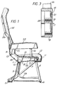
- the seating unit shown in Figure 1 is constructed on a support frame comprising two tubular transverse parallel beams 1, 2, of circular cross section, carried on legs 3, 4 having feet 5, 6 respectively for engaging the floor of a vehicle and braced by a diagonal strut 7.
- the beams 1, 2 are joined by two or more spaced parallel generally horizontal longitudinal members, perpendicular to the beams, one of which, 8, is shown at the near side of the seating unit.
- the other longitudinal members are of a more conventional shape in this seating unit, but they could be similar to the member 8. For simplicity, only one other longitudinal member 9 is shown in the concealed detail. There is a longitudinal member at each side and one between each pair of adjacent seats provided by the unit.
- the parallel beams 1, 2 are closely fitted in bores 10, 11 in the longitudinal member 8 and similar bores in the other longitudinal members, thus providing a rigid structure and they are secured by clamping screws (not shown) in the longitudinal members.
- Bottom seat cushions 12 are supported by the parallel beams 1, 2.
- All the longitudinal members are extended rearwardly and upwardly from their bores 10, through which the rearmost parallel beam 1 passes, to provide pivotal mountings 13 for the backrests 14 for the seats.
- the side longitudinal member 8, however, is formed as a single integral part with an armrest member, being further extended upwardly to provide a rear armrest support 15 and with an integral front armrest supporting strut 16, the upper ends of the rear support 15 and the front strut 16 being joined to an armrest top support portion.
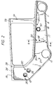
- FIG. 2 shows the side of the component which will be outermost when it is mounted in the support frame.
- the open ends of the bores 10, 11 which are to receive the ends of the transverse beams 1, 2 and of the bore 13 in which the backrest 14 is to be mounted are visible on this side and in previous seating constructions they would be covered by a shaped faring in the finished seat.
- the longitudinal member 8 has a shallow recess 17 enclosing these constructional details, with an undercut peripheral lip 18.
- This not only gives a neat appearance to the finished seat but is cheaper and more easily fitted than the usual shaped faring. It can also be replaced quite easily.
- Further advantages may be utilised by vehicle operators, for example to identify different rows of seats by fitting differently coloured panels 19; to give an individual appearance to a vehicle by fitting panels printed with the insignia of a charterer of the vehicle; or to advertise by fitting panels printed with advertising matter.
- the integral armrest member and longitudinal member 8 itself may also be coloured, for example by anodising if it is of aluminium or an alloy or by self colouring if it is of a plastics/fibre composite material.
- Six holes 20 are formed in the base of the recess 17 to receive fastenings for mounting a buffer bar 21, as shown in Figure 1, and the panel 19 has aligned holes through which the fastenings can pass, so that impact forces applied by passengers or service trolleys are transmitted directly to the member 8.
- An upholstered armrest top 22 is mounted on the armrest top support portion, being secured in bores 23 in its top surface.
- a hole 24 in the top support portion provides for the passage of control cables, for example for the seat recline mechanism and for audio supply, into the armrest top 22.
- the member 8 also has the usual bores 25 for mounting a table 26, 27 for a seat belt anchorage, 28 for mounting the baggage bar 29, and 30 for anchoring the seat recline mechanism. In the finished seating unit, all these bores and elements fitted in them are concealed by the panel 19 as shown in Figure 1.
- the armrest top support portion is little more than a flat strut, it could be shaped to provide the whole or substantially the whole of an armrest. In the latter case some padding would be mounted on its upper surface.
Description
- Seating for passengers in vehicles is commonly provided on seating units comprising two or more seats abreast. British Patent Specification No. 1,121,123 discloses such a unit in which the seat portion is in the form of a trough. Usually, however, such a seating unit is constructed on a support frame comprising two transverse parallel beams, substantially horizontal in the normal upright position of the seating unit. The transverse parallel beams are usually tubes of circular cross section, carried on legs having feet for engaging mountings on the floor of the vehicle. The transverse parallel beams are joined by two or more spaced longitudinal members, perpendicular to the beams and generally horizontal in the normal upright position of the seating unit. There is usually a longitudinal member at each side of a seating unit and at least one between each pair of adjacent seats. The transverse parallel beams enter or pass through bores in the longitudinal members, in which they are a close fit to provide a rigid structure. The bottom seat cushions are supported by the transverse parallel beams and/or the longitudinal members. The longitudinal members are extended rearwardly and upwardly from their bores through which the rearmost of the transverse parallel beams passes, to provide mountings, usually pivotal, for the backrests for the seats. Examples of such a support frame are described in British Patent Specification No. 2 035 790 and PCT Publication No. WO 82/03366.
- Side armrests are usually mounted on the longitudinal members at the sides of the support frame and intermediate armrests for defining and separating the seats are mounted on longitudinal members between adjacent seats or on parts of the frame adjacent to those longitudinal members.
- The side armrest at a side of the seating unit which is to be adjacent to an aisle of a vehicle in which it is fitted must have sufficient strength to resist the leverage forces applied by passengers entering and leaving seats as well as impact forces which may be applied by passengers moving in the aisle or by trollies used to serve passengers occupying the seats. Such a side armrest is usually bolted to the flank of the side longitudinal member. The forces mentioned produce bending and shearing loads on the bolts and to resist these forces the bolts, the side armrest and the side longitudinal member must be of massive construction. To conceal the constructional details and give a neat appearance, it is usual to fit a shaped faring of reinforced plastics material over at least a part of the aisle side armrest and the longitudinal member on which it is mounted.
- According to this invention, a support frame for a vehicle passenger seating unit comprising two transverse parallel beams carried on legs for attachment to the floor of a vehicle and joined by at least two spaced generally horizontal longitudinal members and an armrest member comprising rear and front armrest support struts and an armrest top support portion is characterized in that said armrest member is formed as a single integral part with one of the said longitudinal members.
- This arrangement simplifies the construction and assembly of a seating unit and enables increased strength to be provided without unduly massive construction.
- In the case of a longitudinal member for the side of a support frame which is to be adjacent to an aisle when the support frame is mounted in a vehicle, constructional details enabling it to be secured to the other parts of the frame and for mounting other parts of the seat would be exposed on its side which is to be outermost when it is in position in the support frame. These constructional details include the bores and the ends of the transverse parallel beams received in them and mountings for the backrest parts of the seat. According to a further feature of the invention, when the said armrest member is formed as a single integral part with such a longitudinal member, the said longitudinal member has a recess in its said side, having a wall surrounding and enclosing such constructional details, and a separate panel is provided to fit in the mouth of the recess to conceal them. The recess may be utilised to accommodate other elements of the seating unit, such as mechanical control cables, electric cables and electrical components such as components of an audio system.
- The edge of the wall of the recess is preferably undercut so that the panel can be snapped into the recess and will be self-retaining once so fitted.
- The invention includes a vehicle seating unit including a support frame as described above and a vehicle including such a seating unit.
- The invention not only reduces the number of parts in the seating unit and thereby provides savings in assembly time and labour, but provides, in the case of a side armrest, a structure capable of withstanding the aforementioned forces with a significant saving of weight and width, measured in the lateral direction of the seating unit, so that increased space may be provided for passengers. As there is no bolting of armrest to longitudinal member, a neater appearance results and it is not necessary to use a faring over the longitudinal member, as hitherto.
- An embodiment of the invention is illustrated by the accompanying drawings, in which :
- Figure 1
- is a side elevation of a vehicle seating unit,
- Figure 2
- is a side elevation of a side longitudinal member of the support frame of the seating unit shown in Figure 1, and
- Figure 3
- is a section on the line A-A of Figure 2.
- The seating unit shown in Figure 1 is constructed on a support frame comprising two tubular transverse parallel beams 1, 2, of circular cross section, carried on
legs 3, 4 having feet 5, 6 respectively for engaging the floor of a vehicle and braced by a diagonal strut 7. The beams 1, 2 are joined by two or more spaced parallel generally horizontal longitudinal members, perpendicular to the beams, one of which, 8, is shown at the near side of the seating unit. The other longitudinal members are of a more conventional shape in this seating unit, but they could be similar to themember 8. For simplicity, only one otherlongitudinal member 9 is shown in the concealed detail. There is a longitudinal member at each side and one between each pair of adjacent seats provided by the unit. The parallel beams 1, 2 are closely fitted inbores 10, 11 in thelongitudinal member 8 and similar bores in the other longitudinal members, thus providing a rigid structure and they are secured by clamping screws (not shown) in the longitudinal members.Bottom seat cushions 12 are supported by the parallel beams 1, 2. All the longitudinal members are extended rearwardly and upwardly from theirbores 10, through which the rearmost parallel beam 1 passes, to providepivotal mountings 13 for thebackrests 14 for the seats. The sidelongitudinal member 8, however, is formed as a single integral part with an armrest member, being further extended upwardly to provide arear armrest support 15 and with an integral frontarmrest supporting strut 16, the upper ends of therear support 15 and thefront strut 16 being joined to an armrest top support portion. - The integral armrest member and side
longitudinal member 8, which will be adjacent to an aisle when the seating unit is fitted in a vehicle, is shown in more detail in Figures 2 and 3. Figure 2 shows the side of the component which will be outermost when it is mounted in the support frame. The open ends of thebores 10, 11 which are to receive the ends of the transverse beams 1, 2 and of thebore 13 in which thebackrest 14 is to be mounted are visible on this side and in previous seating constructions they would be covered by a shaped faring in the finished seat. Instead of this, thelongitudinal member 8 has ashallow recess 17 enclosing these constructional details, with an undercutperipheral lip 18. When the seating unit is assembled, a separateflat panel 19, shown in chain-dotted lines, is fitted in this recess, being of such dimensions that it may be snapped into place behind thelip 18 and will be self-retaining. This not only gives a neat appearance to the finished seat but is cheaper and more easily fitted than the usual shaped faring. It can also be replaced quite easily. Further advantages may be utilised by vehicle operators, for example to identify different rows of seats by fitting differentlycoloured panels 19; to give an individual appearance to a vehicle by fitting panels printed with the insignia of a charterer of the vehicle; or to advertise by fitting panels printed with advertising matter. The integral armrest member andlongitudinal member 8 itself may also be coloured, for example by anodising if it is of aluminium or an alloy or by self colouring if it is of a plastics/fibre composite material. - Six
holes 20 are formed in the base of therecess 17 to receive fastenings for mounting abuffer bar 21, as shown in Figure 1, and thepanel 19 has aligned holes through which the fastenings can pass, so that impact forces applied by passengers or service trolleys are transmitted directly to themember 8. - An
upholstered armrest top 22 is mounted on the armrest top support portion, being secured inbores 23 in its top surface. Ahole 24 in the top support portion provides for the passage of control cables, for example for the seat recline mechanism and for audio supply, into thearmrest top 22. Themember 8 also has theusual bores 25 for mounting a table 26, 27 for a seat belt anchorage, 28 for mounting thebaggage bar panel 19 as shown in Figure 1. - Although in the embodiment shown in the drawings the armrest top support portion is little more than a flat strut, it could be shaped to provide the whole or substantially the whole of an armrest. In the latter case some padding would be mounted on its upper surface.
Claims (5)
- A support frame for a vehicle passenger seating unit comprising two transverse parallel beams (1,2) carried on legs (3,4) for attachment to the floor of a vehicle and joined by at least two spaced generally horizontal longitudinal members (8,9) and an armrest member comprising rear and front armrest support struts (15,16) and an armrest top support portion, characterized in that said armrest member is formed as a single integral part with one of the said longitudinal members.
- A support frame as claimed in Claim 1 wherein the said armrest member is formed as a single integral part with the longitudinal member (8) which is to be adjacent to an aisle when the seating unit is fitted in a vehicle, characterized by a recess (17) in the side of the longitudinal member (8) which is to be outermost with respect to the seating unit, surrounding and enclosing constructional details of its attachment to other parts of the support frame and of the seating unit, and in that a separate panel (19) is provided to fit in the mouth of the recess to conceal those details.
- A support frame as claimed in Claim 2, characterized in that the edges (18) of the recess (17) are undercut and in that the panel (19) is so dimensioned that it can be snapped into the recess (17) and will be self-retaining once fitted in the recess.
- A vehicle seating unit, characterized in that it includes a support frame as claimed in Claim 3.
- A vehicle, characterized in that it includes a seating unit as claimed in Claim 4.
Applications Claiming Priority (2)
| Application Number | Priority Date | Filing Date | Title |
|---|---|---|---|
| GB8814536 | 1988-06-18 | ||
| GB888814536A GB8814536D0 (en) | 1988-06-18 | 1988-06-18 | Vehicle passenger seating |
Publications (3)
| Publication Number | Publication Date |
|---|---|
| EP0348096A2 EP0348096A2 (en) | 1989-12-27 |
| EP0348096A3 EP0348096A3 (en) | 1991-04-24 |
| EP0348096B1 true EP0348096B1 (en) | 1994-08-03 |
Family
ID=10638943
Family Applications (1)
| Application Number | Title | Priority Date | Filing Date |
|---|---|---|---|
| EP89306029A Expired - Lifetime EP0348096B1 (en) | 1988-06-18 | 1989-06-14 | Vehicle passenger seating |
Country Status (7)
| Country | Link |
|---|---|
| EP (1) | EP0348096B1 (en) |
| JP (1) | JPH02106449A (en) |
| CN (1) | CN1021645C (en) |
| AU (1) | AU631549B2 (en) |
| DE (1) | DE68917223T2 (en) |
| ES (1) | ES2060770T3 (en) |
| GB (1) | GB8814536D0 (en) |
Families Citing this family (6)
| Publication number | Priority date | Publication date | Assignee | Title |
|---|---|---|---|---|
| DE3918500A1 (en) * | 1989-06-07 | 1990-12-13 | Keiper Recaro Gmbh Co | VEHICLE SEAT, PARTICULARLY PASSENGER SEAT |
| DE19501743A1 (en) * | 1995-01-23 | 1996-07-25 | Daimler Benz Ag | Seat for motor vehicles, in particular for vans |
| EP0854795A1 (en) * | 1995-11-07 | 1998-07-29 | C.A.B. Voertuigtechniek N.V. | Securing means for a vehicle seat |
| NL1001595C2 (en) * | 1995-11-07 | 1997-05-13 | C A B Voertuigtechniek N V | Seat securing assembly for passenger vehicles, e.g. buses |
| DE19638473A1 (en) * | 1996-09-20 | 1998-03-26 | Vogel Ind Gmbh | Arm rest for motor vehicle seat |
| JP5972114B2 (en) * | 2012-08-31 | 2016-08-17 | 株式会社総合車両製作所 | Vehicle seat sleeve divider |
Family Cites Families (6)
| Publication number | Priority date | Publication date | Assignee | Title |
|---|---|---|---|---|
| US4099780A (en) * | 1975-06-05 | 1978-07-11 | Recaro Gmbh & Co. | Airline passenger seat |
| GB2022403B (en) * | 1978-04-25 | 1983-01-26 | Aircraft Furnishing Ltd | Seat |
| US4186964A (en) * | 1978-10-23 | 1980-02-05 | Fairchild Industries, Inc. | Seat armrest |
| US4229040A (en) * | 1978-11-27 | 1980-10-21 | Fairchild Industries, Inc. | Seat support structure |
| AU530564B2 (en) * | 1979-08-28 | 1983-07-21 | Qantas Airways Ltd. | Aircraft chair leg rest |
| EP0076280A1 (en) * | 1981-03-30 | 1983-04-13 | TOLL, Ian Cecil | Improvements in aircraft seating |
-
1988
- 1988-06-18 GB GB888814536A patent/GB8814536D0/en active Pending
-
1989
- 1989-06-14 ES ES89306029T patent/ES2060770T3/en not_active Expired - Lifetime
- 1989-06-14 DE DE68917223T patent/DE68917223T2/en not_active Expired - Fee Related
- 1989-06-14 EP EP89306029A patent/EP0348096B1/en not_active Expired - Lifetime
- 1989-06-15 AU AU36429/89A patent/AU631549B2/en not_active Ceased
- 1989-06-16 CN CN89104213A patent/CN1021645C/en not_active Expired - Fee Related
- 1989-06-19 JP JP1156637A patent/JPH02106449A/en active Pending
Also Published As
| Publication number | Publication date |
|---|---|
| EP0348096A2 (en) | 1989-12-27 |
| DE68917223D1 (en) | 1994-09-08 |
| JPH02106449A (en) | 1990-04-18 |
| AU631549B2 (en) | 1992-12-03 |
| ES2060770T3 (en) | 1994-12-01 |
| EP0348096A3 (en) | 1991-04-24 |
| GB8814536D0 (en) | 1988-07-27 |
| AU3642989A (en) | 1989-12-21 |
| CN1038983A (en) | 1990-01-24 |
| CN1021645C (en) | 1993-07-21 |
| DE68917223T2 (en) | 1994-11-17 |
Similar Documents
| Publication | Publication Date | Title |
|---|---|---|
| US5800013A (en) | Vehicle passenger seating | |
| US6824213B2 (en) | Passenger seat with seat electronics unit and beam therefor | |
| US4375300A (en) | Framing system for aircraft passenger seat | |
| CN106394362B (en) | Cushion module for vehicle seat assembly | |
| US4776635A (en) | Modular seat for railway cars | |
| US4489978A (en) | Support structure for maximizing or equalizing luggage space under vehicle seats | |
| US4936620A (en) | Arrangement or organization of seats inside the passenger area of vehicle | |
| US8931847B2 (en) | Passenger seating assemblies and aspects thereof | |
| US4848843A (en) | Multiple seat chair structure | |
| EP2550200A1 (en) | Passenger seat assembly with associated floor panel and aircraft sidewall attachment, and method | |
| US6802568B1 (en) | Segmented beam aircraft passenger seat | |
| EP1013545B1 (en) | Airplane passenger privacy and support apparatus | |
| US20040212243A1 (en) | Curved beam aircraft passenger seat | |
| JP3044066B2 (en) | Seats, especially public transport vehicle seats | |
| WO1997007021B1 (en) | High-capacity, high-comfort split-level seating | |
| JP2009515761A (en) | Mounting structure for aircraft cabin interior components | |
| US3124390A (en) | Seating pad attachment | |
| RU2252156C2 (en) | Suspended seat with fastening on pillar of passenger vehicle body load-bearing structure | |
| EP0348096B1 (en) | Vehicle passenger seating | |
| FI69019C (en) | PASSAGERARSAETE | |
| US20160340045A1 (en) | Aircraft seat mounting device | |
| KR101957051B1 (en) | Chair for Railway vehicle | |
| US4426114A (en) | Unitary supporting and seat frame for rigid seat | |
| EP3552965A1 (en) | Seat assembly for vehicles | |
| KR20050016418A (en) | Seats for public transport vehicle |
Legal Events
| Date | Code | Title | Description |
|---|---|---|---|
| PUAI | Public reference made under article 153(3) epc to a published international application that has entered the european phase |
Free format text: ORIGINAL CODE: 0009012 |
|
| AK | Designated contracting states |
Kind code of ref document: A2 Designated state(s): BE DE ES FR GB IT LU NL |
|
| PUAL | Search report despatched |
Free format text: ORIGINAL CODE: 0009013 |
|
| AK | Designated contracting states |
Kind code of ref document: A3 Designated state(s): BE DE ES FR GB IT LU NL |
|
| 17P | Request for examination filed |
Effective date: 19911017 |
|
| RAP1 | Party data changed (applicant data changed or rights of an application transferred) |
Owner name: FLIGHT EQUIPMENT & ENGINEERING LIMITED |
|
| 17Q | First examination report despatched |
Effective date: 19921102 |
|
| RAP1 | Party data changed (applicant data changed or rights of an application transferred) |
Owner name: FLIGHT EQUIPMENT & ENGINEERING LIMITED |
|
| GRAA | (expected) grant |
Free format text: ORIGINAL CODE: 0009210 |
|
| AK | Designated contracting states |
Kind code of ref document: B1 Designated state(s): BE DE ES FR GB IT LU NL |
|
| REF | Corresponds to: |
Ref document number: 68917223 Country of ref document: DE Date of ref document: 19940908 |
|
| RAP2 | Party data changed (patent owner data changed or rights of a patent transferred) |
Owner name: FLIGHT EQUIPMENT AND ENGINEERING LIMITED |
|
| ITF | It: translation for a ep patent filed |
Owner name: CALVANI SALVI E VERONELLI S.R.L. |
|
| ET | Fr: translation filed | ||
| REG | Reference to a national code |
Ref country code: ES Ref legal event code: FG2A Ref document number: 2060770 Country of ref document: ES Kind code of ref document: T3 |
|
| PGFP | Annual fee paid to national office [announced via postgrant information from national office to epo] |
Ref country code: BE Payment date: 19950310 Year of fee payment: 7 |
|
| PGFP | Annual fee paid to national office [announced via postgrant information from national office to epo] |
Ref country code: FR Payment date: 19950320 Year of fee payment: 7 |
|
| PGFP | Annual fee paid to national office [announced via postgrant information from national office to epo] |
Ref country code: LU Payment date: 19950501 Year of fee payment: 7 |
|
| PGFP | Annual fee paid to national office [announced via postgrant information from national office to epo] |
Ref country code: GB Payment date: 19950529 Year of fee payment: 7 |
|
| PLBE | No opposition filed within time limit |
Free format text: ORIGINAL CODE: 0009261 |
|
| STAA | Information on the status of an ep patent application or granted ep patent |
Free format text: STATUS: NO OPPOSITION FILED WITHIN TIME LIMIT |
|
| PGFP | Annual fee paid to national office [announced via postgrant information from national office to epo] |
Ref country code: ES Payment date: 19950613 Year of fee payment: 7 |
|
| PGFP | Annual fee paid to national office [announced via postgrant information from national office to epo] |
Ref country code: NL Payment date: 19950627 Year of fee payment: 7 |
|
| 26N | No opposition filed | ||
| PGFP | Annual fee paid to national office [announced via postgrant information from national office to epo] |
Ref country code: DE Payment date: 19950830 Year of fee payment: 7 |
|
| PG25 | Lapsed in a contracting state [announced via postgrant information from national office to epo] |
Ref country code: LU Free format text: LAPSE BECAUSE OF NON-PAYMENT OF DUE FEES Effective date: 19960614 Ref country code: GB Effective date: 19960614 |
|
| PG25 | Lapsed in a contracting state [announced via postgrant information from national office to epo] |
Ref country code: ES Free format text: LAPSE BECAUSE OF EXPIRATION OF PROTECTION Effective date: 19960615 |
|
| PG25 | Lapsed in a contracting state [announced via postgrant information from national office to epo] |
Ref country code: BE Effective date: 19960630 |
|
| BERE | Be: lapsed |
Owner name: FLIGHT EQUIPMENT & ENGINEERING LTD Effective date: 19960630 |
|
| PG25 | Lapsed in a contracting state [announced via postgrant information from national office to epo] |
Ref country code: NL Effective date: 19970101 |
|
| GBPC | Gb: european patent ceased through non-payment of renewal fee |
Effective date: 19960614 |
|
| PG25 | Lapsed in a contracting state [announced via postgrant information from national office to epo] |
Ref country code: FR Effective date: 19970228 |
|
| PG25 | Lapsed in a contracting state [announced via postgrant information from national office to epo] |
Ref country code: DE Effective date: 19970301 |
|
| NLV4 | Nl: lapsed or anulled due to non-payment of the annual fee |
Effective date: 19970101 |
|
| REG | Reference to a national code |
Ref country code: FR Ref legal event code: ST |
|
| REG | Reference to a national code |
Ref country code: ES Ref legal event code: FD2A Effective date: 19990601 |
|
| PG25 | Lapsed in a contracting state [announced via postgrant information from national office to epo] |
Ref country code: IT Free format text: LAPSE BECAUSE OF NON-PAYMENT OF DUE FEES;WARNING: LAPSES OF ITALIAN PATENTS WITH EFFECTIVE DATE BEFORE 2007 MAY HAVE OCCURRED AT ANY TIME BEFORE 2007. THE CORRECT EFFECTIVE DATE MAY BE DIFFERENT FROM THE ONE RECORDED. Effective date: 20050614 |