EP0348073B1 - Schiebedach für Kraftfahrzeuge - Google Patents
Schiebedach für Kraftfahrzeuge Download PDFInfo
- Publication number
- EP0348073B1 EP0348073B1 EP19890305771 EP89305771A EP0348073B1 EP 0348073 B1 EP0348073 B1 EP 0348073B1 EP 19890305771 EP19890305771 EP 19890305771 EP 89305771 A EP89305771 A EP 89305771A EP 0348073 B1 EP0348073 B1 EP 0348073B1
- Authority
- EP
- European Patent Office
- Prior art keywords
- formation
- drive member
- flange
- panel
- opening
- Prior art date
- Legal status (The legal status is an assumption and is not a legal conclusion. Google has not performed a legal analysis and makes no representation as to the accuracy of the status listed.)
- Expired - Lifetime
Links
- 230000015572 biosynthetic process Effects 0.000 claims description 83
- 238000005755 formation reaction Methods 0.000 claims description 83
- 230000008878 coupling Effects 0.000 claims description 28
- 238000010168 coupling process Methods 0.000 claims description 28
- 238000005859 coupling reaction Methods 0.000 claims description 28
- XLYOFNOQVPJJNP-UHFFFAOYSA-N water Substances O XLYOFNOQVPJJNP-UHFFFAOYSA-N 0.000 claims description 24
- 230000000295 complement effect Effects 0.000 claims description 3
- 230000007246 mechanism Effects 0.000 description 3
- 239000011521 glass Substances 0.000 description 2
- 239000002184 metal Substances 0.000 description 2
- 229920003023 plastic Polymers 0.000 description 2
- 239000004033 plastic Substances 0.000 description 2
- 230000014759 maintenance of location Effects 0.000 description 1
- 230000002028 premature Effects 0.000 description 1
- 230000000284 resting effect Effects 0.000 description 1
- 230000000717 retained effect Effects 0.000 description 1
Images


Classifications
-
- B—PERFORMING OPERATIONS; TRANSPORTING
- B60—VEHICLES IN GENERAL
- B60J—WINDOWS, WINDSCREENS, NON-FIXED ROOFS, DOORS, OR SIMILAR DEVICES FOR VEHICLES; REMOVABLE EXTERNAL PROTECTIVE COVERINGS SPECIALLY ADAPTED FOR VEHICLES
- B60J7/00—Non-fixed roofs; Roofs with movable panels, e.g. rotary sunroofs
- B60J7/02—Non-fixed roofs; Roofs with movable panels, e.g. rotary sunroofs of sliding type, e.g. comprising guide shoes
- B60J7/04—Non-fixed roofs; Roofs with movable panels, e.g. rotary sunroofs of sliding type, e.g. comprising guide shoes with rigid plate-like element or elements, e.g. open roofs with harmonica-type folding rigid panels
- B60J7/043—Sunroofs e.g. sliding above the roof
- B60J7/0435—Sunroofs e.g. sliding above the roof pivoting upwardly to vent mode and moving at the outside of the roof to fully open mode
-
- B—PERFORMING OPERATIONS; TRANSPORTING
- B60—VEHICLES IN GENERAL
- B60J—WINDOWS, WINDSCREENS, NON-FIXED ROOFS, DOORS, OR SIMILAR DEVICES FOR VEHICLES; REMOVABLE EXTERNAL PROTECTIVE COVERINGS SPECIALLY ADAPTED FOR VEHICLES
- B60J7/00—Non-fixed roofs; Roofs with movable panels, e.g. rotary sunroofs
- B60J7/02—Non-fixed roofs; Roofs with movable panels, e.g. rotary sunroofs of sliding type, e.g. comprising guide shoes
- B60J7/04—Non-fixed roofs; Roofs with movable panels, e.g. rotary sunroofs of sliding type, e.g. comprising guide shoes with rigid plate-like element or elements, e.g. open roofs with harmonica-type folding rigid panels
- B60J7/043—Sunroofs e.g. sliding above the roof
Definitions
- This invention relates to an opening roof for a motor vehicle of the type in which the front part of an opening in the vehicle roof is covered by a front panel which has side flanges extending downwardly from its side edges and is openable by pivoting upwardly about its front edge and the rest of the opening is covered by a rear panel which has side flanges extending downwardly from its side edges and is openable by sliding, to a position behind the opening, along a pair of tracks located on opposite sides of the opening.
- An opening roof of this type is disclosed in GB-A-2161439.
- a water check flange is secured to the vehicle roof so as to surround the entire periphery of the opening
- side flanges on the front panel are part of a main flange extending downwardly from its front and side edges so as to be below the top of the water check flange when the front panel is in its closed position
- the side flanges on the rear panel are part of a main flange extending downwardly from its side and rear edges so as to project outside and below the top of the water check flange
- a front flange projects downwardly from the front edge of the rear panel to a depth less than the depth of the main flange of the rear panel so as to extend over the water check flange adjacent to each front corner of the rear panel
- an upwardly facing U-shaped channel is formed on the bottom edge of the front flange of the rear panel
- a rear flange extends downwardly from the rear edge of the front panel to a depth less than the depth of the main flange
- any water running off the front and sides of the front panel or the sides and rear of the main panel is deposited on the vehicle roof outside the water check flange. Any water running into the join between the two panels is collected by the U-shaped channel and is discharged from the ends thereof outside the water check flange. Consequently no seals are required to prevent rainwater leaking into the interior of the vehicle when the panels are closed.
- the tracks may be mounted on the vehicle roof laterally outside the water check flange.
- Each of the tracks may support means for opening the panels comprising a drive member movable along the track, a first link coupled to means operative to open the front panel as it slides along the track and having a first coupling formation at its rear end movable between a first position in which it engages with a locking formation on the track and a second position in which:it engages with the drive means, and a second link coupled to slide along the track with the rear panel and having a second coupling formation at its front end movable between a first position in which it engages with a locking formation on the track and a second position in which it engages with the drive means, the first and second coupling formations being so shaped that the first coupling formation is disengaged from the drive member and engaged with its locking formation and the second coupling formation is disengaged from the drive member and engaged with its locking formation during rearward movement of the drive member, and the first coupling formation is disengaged from its locking formation and engaged with the drive member and the second coupling formation is disengaged from its locking formation and engaged with
- the second link has a ramp on its front end arranged to engage with the drive member to retain the second coupling formation in engagement with said locking formation when the drive member is in front of the locking formation.
- a single locking formation is provided on the track and the first coupling formation is arranged to move out of engagement with the drive means simultaneously with movement of the second coupling formation into engagement therewith.
- the means operative to open the front panel may comprise a strut having one end pivotally connected to the panel and having a first pivot formation at its other end engaging in an arcuate slot in a side wall of the first link and a second pivot formation intermediate between the ends of the strut engaging in the arcuate slot so as to be at the front of the slot when the first panel is in its closed position, rearward movement of the first link causing the pivot formations to move along the arcuate slot thereby pivoting the strut relative to the track so as to raise the rear edge of the panel, the arcuate slot having an upwardly extending branch slot aligned with the position of the second pivot formation when the first pivot formation is at the front end of the arcuate slot, the branch slot permitting the second pivot formation to disengage from the arcuate slot as continued rearward movement of the first link causes continued pivotal movement of the strut about the first pivot formation.
- the strut has a cam formation adjacent to the first pivot formation arranged to engage with a complementary formation on the first link to retain the first pivot formation at the front end of the arcuate slot when the second pivot formation is disengaged from both the arcuate slot and the branch slot.
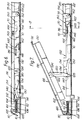
- the roof 10 of a motor car contains an opening 12 surrounded by a frame 14.
- the frame 14 has an upwardly extending water check flange 16 extending around the entire periphery of the opening, the portion 18 of the flange 16 extending along the rear edge of the opening being higher than the rest of the flange 16.
- the frame 14 also includes a pair of slide tracks 20 and 22 each extending along a respective side of the opening and also projecting behind the opening 12.
- a rear panel 24 is slidably mounted on the tracks 20 and 22 and a front panel 26 is pivotally mounted on the part of the flange 16 extending along the front edge of the opening.
- the front and side edges of the front panel 26 carry a downwardly extending main flange 28.
- a hinge 30 connects the bottom edge of the part of the flange 28 extending along the front of the panel 26 to the corresponding part of the water check flange 16.
- a rear flange 32 extends downwardly from the rear edge of the front panel 26 to a depth of approximately half that of the main flange 28.
- the rear panel 24 has a main flange 34 extending downwardly from its side and rear edges to a depth substantially equal to the depth of the main flange 28 of the front panel 26.
- the side portions of the flange 34 carry respective and rear guide shoes 36 and 38 which engage in channels 40 in the tracks 20 and 22 respectively (see Figure 5). Although the shoes 36 and 38 are shown as merely resting in the groove 40, it should be understood that interlocking formations of known type are provided to prevent the panel 25 from being lifted vertically away from the tracks 20 and 22.
- a front flange 42 extends downwardly from the front edge of the rear panel 24 to a depth such that its bottom edge is above the level of the side portions of the water check flange 16 but below the level of the rear portion 18 thereof.
- An upwardly facing U-shaped channel 44 is formed on the bottom edge of the front flange 42.
- its end sections 46 outside the water check flange 16, slope downwardly so as to facilitate drainage of water therefrom.
- the front panel 26 When it is desired to open the roof, the front panel 26 is first pivoted upwardly at least sufficiently to disengage its rear flange 32 from the channel 44.
- the rear panel 24 can then be moved rearwardly to the extent desired, the rearward limit of its range of movement being defined by engagement of its front flange 42 with the higher rear part 18 of the water check flange 16.
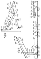
- Figures 6 to 10 illustrate another embodiment of the invention in which the opening 12 in the roof 10 of the motor car shown in Figures 1 and 2 is surrounded by a frame including a front member 60 ( Figure 6) and a pair of side members 62 ( Figure 8).
- the frame includes an upwardly extending water check flange 64, similar to the flange 16 of Figures 1 to 5.
- a drainage channel 72 extends across the front edge of the rear panel 20 and interlocks with a downwardly extending flange 74 on the rear edge of the front panel 66.
- the channel 72 discharges outside the water check flange 64, the arrangement thus being similar to that provided by the channel 44 illustrated in Figures 1 to 5.
- the rear panel 70 comprises a glass pane 76 mounted in a metal or plastics frame 78.
- the drainage panel 72 is formed integrally with the front part of the frame 78 while the side and rear parts thereof include a downwardly projecting flange 80 which is located outside the water check flange 64 and a downwardly inclined outer flange 82 which is located outside the frame bounding the opening in the vehicle roof 10.
- the front panel 66 consists of a glass pane 84 mounted in a metal or plastics frame 86.
- the flange 74 is formed integrally with the rear edge of the frame 86 while the front and side edges thereof carry a downwardly extending flange 88 which is located outside the water check flange 64, and an outwardly inclined flange 89 similar to the flange 82 on the rear panel 70.
- each of the side members 62 of the frame has a central open-topped channel 90 of rectangular cross-section and inner and outer side channels 92 and 94, each of which has a bottom part of circular cross-section together with a slot of width less than the diameter of the bottom part communicating with the top of the rail.
- a drive member 96 has a rectangular central part extending transversely across the track 62 together with respective end limbs projecting downwardly into the grooves 92 and 94 with respective cylindrical formations 98 and 100 on their lower ends.
- the cylindrical formation 98 in the inner groove 92 is clamped onto a drive cable 102 which extends along the inner groove 92 and a corresponding channel 104 of circular cross-section formed at the inner end of a closed channel in the front frame member 60.
- the channel 106 also has an outer end portion 108 of circular cross-section containing a second drive cable 110 which extends across the front of the roof opening and then down the outer groove 100 in the frame member 62 on the right hand side of the opening where it is engaged by the cylindrical formation 100 on the outer end of the corresponding drive bar 96.
- the two side members 62 and their associated mechanisms are symmetrical about the longitudinal centre line of the car.
- the channel 106 accommodates a sprocket 112, the teeth of which engage with complementary formations on the drive cables 102 and 110.
- a drive knob 114 located within the vehicle, is rotationally coupled to the sprocket 112. Rotation of the knob 114 therefore causes the cables 102 and 110 to move in opposite directions across the front opening and consequently in the same direction down the sides thereof, thus moving the two drive members 96 in unison with each other.
- the mechanism coupling the drive member 96 to the front panel 86 comprises a strut 120 which is connected by a pivot pin 122 to a bracket 124 secured to the underside of the frame 86 of the front panel 66.
- the strut 120 has a second pivot pin 128 which engages in a main arcuate slot 130 in a first link 132.
- the arcuate slot 130 has a branch slot 134, also of arcuate shape centred on the front end of the slot 130.
- a third pin 136 projects from one side of the strut 120 at the same distance from the pivot pin 128 as the radius of the branch slot 134.
- the strut 120 can pivot thereabout, moving the pin first along and then out of the branch slot 134.
- the pivot pin 128 is retained at the front of the slot 130 when the pin 136 is clear of the slot 130 first by engagement of the pin 136 with the walls of the branch slot 134 and then, after the pin 136 has moved clear of the branch slot 134, by inter-engagement of a convex cam formation 138 on the side of the strut 120 with a concave cam formation 140 on the side of the first link 132.
- the link 132 has a ramp 142.
- a recess 144 is formed in the top surface of the link 132 in front of the ramp 142.
- the walls of the recess 144 are sloped in the opposite direction to the ramp 142.
- the link 132 has a projection 146 on its bottom surface in alignment with the recess 144.
- the top surface 148 of the part of the link 132 behind the recess 144 is lower than the top surface immediately in front of this recess, this difference in height, the depth of the recess 144 below the surface 148 and the height of the projection 146 all being substantially equal to the thickness of the rectangular part of the drive member 96.
- a second link 150 couples the drive member 96 to the rear panel 70 via a pivot pin 152 which engages in a bracket 154 secured to the frame 78.
- the second link 150 In front of the pivot pin 152, the second link 150 has a recess 154 in its upper surface and a projection 156 on its lower surface which are similar to the projection 144 and recess 146 of the first link 132 except that the walls of the recess 154 slope in the opposite direction.
- the top surface of the portion 158 of the second link 150 located in front of the recess 154 is lower than the top surface behind such recess by an amount equal to the thickness of the transverse part of the drive member 96.
- the thickness of the portion 148 of the first link 132 and the portion 158 of the second link 150 is such that there is room for the drive bar to pass thereabove only when the projections 146, 156 respectively are received in the cut-out 160.
- a cut-out 160 is formed in the base of the channel 90 in the track 62 in alignment with the projections 146 and 156 when the mechanism is in the position illustrated in Figure 7.
- Figure 6 illustrates the roof with both panels 66 and 70 in their closed positions.
- the strut 120 is substantially horizontal, the pin 136 being at the rear end of the main arcuate slot 130 and the pin 128 at an intermediate position along its length.
- the first link 132 is held in place by engagement of the drive member 96 in the recess 144 while the second link 150, and, with it, the rear panel 70, is held in position by engagement of the projection 156 in the cut-out 160 in the track, disengagment being prevented by the drive member 96 which overlies the front end of the second link 150.
- the drive member 96 is moved rearwardly, pulling the first link 132 rearwardly by engagement with the rear edge of the recess 144. Although this rear edge is inclined, the downward component of force on the front link 132 is resisted by engagement of the projection 146 with the bottom of the channel 90 in the side member 62. Initial rearward movement of the first link 132 causes the pins 128 and 136 to move along the main arcuate slot 130, thereby lifting the rear edge of the front panel 66.
- the panels can be returned to their closed position by forward movement of the drive member 96.
- the rectangular channel 90 has a groove 162 in its inner side wall.
- the rear edge of the rear panel is supported on a conventional guide shoe which is received in the rectangular channel 90 and has a formation engaging in the side groove 162.
Landscapes
- Engineering & Computer Science (AREA)
- Mechanical Engineering (AREA)
- Body Structure For Vehicles (AREA)
- Power-Operated Mechanisms For Wings (AREA)
Claims (8)
- Schiebedach für ein Kraftfahrzeug, bei dem der Vorderteil einer Öffnung (12) in dem Fahrzeugdach (10) von einer Vorderplatte (26, 66) abgedeckt ist, die Seitenflansche besitzt, welche sich von ihren Seitenkanten nach unten erstrecken, und die durch Hochschwenken an ihre Vorderkante zu öffnen ist, während der Rest der Öffnung (12) von einer Hinterplatte (24, 70) abgedeckt ist, die Seitenflansche besitzt, welche sich von ihren Seitenkanten aus nach unten erstrecken, und die durch Verschieben entlang einem Paar von Spuren (40, 62) auf einander entgegengesetzten Seiten der Öffnung (12) zu einer Stelle hinter der Öffnung (12) zu öffnen ist, dadurch gekennzeichnet, daß an dem Fahrzeugdach (10) ein Wasserrückhalteflansch (16, 64) derart befestigt ist, daß er den gesamten Umfang der Öffnung (12) angibt, Seitenflansche an der Vorderplatte (26, 66) Teil eines Hauptflansches (80) sind, der sich von ihrer Vorderkante und ihren Seitenkanten aus derart nach unten erstreckt, daß er unterhalb des Oberteils des Wasserrückhalteflansches (16, 64) liegt, wenn sich die Vorderplatte in ihrer geschlossenen Stellung befindet, die Seitenflansche an der Hinterplatte (24, 70) Teil eines Hauptflansches (34, 80) sind, der sich von ihren Seitenkanten und ihrer Hinterkante derart nach unten erstreckt, daß er außerhalb und unterhalb des Oberteils des Wasserrückhalteflansches (16, 64) vorsteht, ein Vorderflansch (42) von der Vorderkante der Hinterplatte (24, 70) bis zu einer Tiefe nach unten absteht, die geringer ist als die Tiefe des Hauptflansches (34, 80) der Hinterplatte (24, 70), an sich benachbart zu jeder vorderen Ecke der Hinterplatte (24, 70) über den Wasserrückhalteflansch (16, 64) zu erstrecken, an der Unterkante des Vorderflansches der Hinterplatte (24, 70) ein nach oben weisender U-förmiger Kanal (42, 72) ausgebildet ist, und sich ein Hinterflansch (32, 74) von der Hinterkante der Vorderplatte (26, 66) aus bis zu einer Tiefe nach unten erstreckt, die geringer ist als die Tiefe des Hauptflansches (80) der Vorderplatte (26, 66), so daß der Hinterflansch (32, 74) in dem U-förmigen Kanal (44, 72) aufgenommen wird, wenn sich beide Platten (26, 24; 66, 70) in ihrer geschlossenen Stellung befinden.
- Schiebedach für ein Kraftfahrzeug nach Anspruch 1, bei dem die Spuren (40, 62) an dem Fahrzeugdach (10) seitlich außerhalb des Wasserrückhalteflansches (16, 64) angebracht sind.
- Schiebedach für ein Kraftfahrzeug nach Anspruch 1 oder 2, bei dem jede der Spuren (62) eine Einrichtung zum Öffnen der Platten trägt, anfassend ein Antriebselement (96), welches entlang der Spur (62) bewegbar ist, ein erstes Verbindungsglied (132), welches an Mittel zum Öffnen der Vorderplatte (60) gekoppelt ist, wenn es entlang der Spur (42) gleitet, und eine erste Kupplungsausbildung (144, 146) an seinem hinteren Ende aufweist, welche beweglich ist zwischen einer ersten Stellung, in der sie mit einer Verriegelungsausbildung (160) an der Spur (62) in Eingriff tritt, und einer zweiten Stellung, in der sie mit dem Antriebselement (96) in Eingriff gelangt, und ein zweites Verbindungsglied (150), welches zur Verschiebung entlang der Spur (62) mit der Hinterplatte (70) gekoppelt ist und eine zweite Kupplungsausbildung (154, 156) an ihrem vorderen Ende aufweist, die beweglich ist zwischen einer ersten Stellung, in der sie in Eingriff mit einer Verriegelungsausbildung (160) an der Spur (62) gelangt, und einer zweiten Stellung, in der sie mit dem Antriebselement (96) in Eingriff tritt, wobei die erste und die zweite Kupplungsausbildung (144, 146; 154, 156) derart geformt ist, daß die erste Kupplungsausbildung (144, 146) sich von dem Antriebselement (96) löst und mit ihrer Verriegelungsausbildung (160) in Eingriff tritt, während die zweite Kupplungsausbildung (154, 156) sich von dem Antriebselement (96) löst und mit ihrer Kupplungsausbildung (160) in Eingriff tritt während der Rückwärtsbewegung des Antriebselementes (96), und die erste Kupplungsausbildung (144, 146) sich von ihrer Verriegelungsausbildung (160) löst und mit dem Antriebselement (96) in Eingriff tritt, während die zweite Kupplungsausbildung (154, 156) sich von ihrer Verriegelungsausbildung (160) löst und mit dem Antriebselement (96) in Eingriff tritt, während das Antriebselement (96) eine Vorwärtsbewegung vollzieht.
- Schiebedach für ein Kraftfahrzeug nach Anspruch 1, 2 oder 3, dadurch gekennzeichnet, daß jede der Spuren (62) eine Einrichtung zum Öffnen der Platten aufweist, welche anfaßt: ein entlang der Spur bewegliches Antriebselement (96), ein erstes Verbindungsglied (132), welches an Mittel zum Öffnen der Vorderplatte (66) gekoppelt ist, wenn es entlang der Spur (62) gleitet, und welches eine erste Kupplungsausbildung (144, 146) an seinem hinteren Ende besitzt, die beweglich ist zwischen einer ersten Stellung, in der sie in Eingriff mit einer Verriegelungsausbildung (160) auf der Spur (62) tritt, und einer zweiten Stellung, in der sie mit dem Antriebselement (96) in Eingriff gelangt, und ein zweites Verbindungsglied (150), welches zur Verschiebung entlang der Spur (62) mit der Hinterplatte (70) gekoppelt ist und eine zweite Kupplungsausbildung (154, 156) an seinem Vorderende aufweist, die beweglich ist zwischen einer ersten Stellung, in der sie in Eingriff tritt mit einer Verriegelungsausbildung (160) an der Spur (62) und einer zweiten Stellung, in der sie in Eingriff mit dem Antriebselement (96) tritt, wobei die erste und die zweite Kupplungsausbildung (144, 146; 154, 156) derart geformt sind, daß die erste Kupplungsausbildung (144, 146) sich von dem Antriebselement (96) löst und in Eingriff mit ihrer Verriegelungsausbildung (160) tritt, und die zweite Kupplungsausbildung (154, 156) sich von dem Antriebselement (96) löst und in Eingriff mit ihrer Verriegelungsausbildung (160) tritt, während das Antriebselement (96) eine Rückwärtsbewegung vollzieht, und die erste Kupplungsausbildung (144, 146) sich von ihrer Verriegelungsausbildung (160) löst und mit dem Antriebselement (96) in Eingriff tritt, während die zweite Kupplungsausbildung (154, 156) sich von ihrer Verriegelungsausbildung (160) löst und mit dem Antriebselement (96) in Eingriff tritt, während das Antriebselement (96) eine Vorwärtsbewegung vollzieht.
- Schiebedach für ein Kraftfahrzeug nach Anspruch 3 oder 4, bei dem das zweite Verbindungsglied (150) an seinem Vorderende eine Rampe aufweist, die derart ausgebildet ist, daß sie mit dem Antriebselement (96) in Eingriff tritt, an die zweite Kupplungsausbildung (154, 156) in Eingriff mit ihrer Verriegelungsausbildung (160) zu halten, wenn das Antriebselement (96) sich vor der Verriegelungsausbildung (160) befindet.
- Schiebedach für ein Kraftfahrzeug nach Anspruch 3, 4 oder 5, bei dem auf der Spur eine einzige Verriegelungsausbildung (160) vorgesehen ist und die erste Kupplungsausbildung (144, 146) derart ausgebildet ist, daß sie sich aus dem Eingriff mit dem Antriebselement (96) zur gleichen Zeit löst, zu der sich die zweite Kupplungsausbildung (154, 156) in den Eingriff mit diesem bewegt.
- Schiebedach für ein Kraftfahrzeug nach Anspruch 3, 4, 5 oder 6 bei dem die Mittel zum Öffnen der Vorderplatte (66) aufweisen: eine Strebe (120), deren eines Ende (122) schwenkbar mit der Platte (66) verbunden ist und eine erste Schwenkausbildung (128) an ihrem anderen Ende aufweist, welche in einen bogenförmigen Schlitz (130) in einer Seitenwand des ersten Verbindungsgliedes (132) eingreift, sowie eine zweite Schwenkausbildung (136) zwischen den Enden der Strebe (120) aufweist, welche in den bogenförmigen Schlitz (130) eingreift, an vorne in dem Schlitz (130) zu liegen, wenn sich die erste Platte in ihrer geschlossenen Stellung befindet, wobei eine Rückwärtsbewegung des ersten Verbindungsgliedes (132) die Schwenkausbildungen (128, 136) veranlaßt, sich entlang dem bogenförmigen Schlitz (130) zu bewegen und dabei die Strebe (120) relativ zu der Spur (62) zu verschwenken und so die Hinterkante der Platte (66) anzuheben, wobei der bogenförmige Schlitz (130) einen sich nach oben erstreckenden Verzweigungsschlitz (134) besitzt, der mit der Lage der zweiten Schwenkausbildung (136) ausgerichtet ist, wenn die erste Schwenkausbildung (128) sich am vorderen Ende des bogenförmigen Schlitzes (130) befindet, so daß der Verzweigungsschlitz (134) ermöglichst, daß sich die zweite Schwenkausbildung (136) aus dem bogenförmigen Schlitz (130) löst, wenn eine fortgesetzte Rückwärtsbewegung des ersten Verbindungsgliedes (132) eine fortgesetzte Schwenkbewegung der Strebe (120) an die erste Schwenkausbildung (128) veranlaßt.
- Schiebedach für ein Kraftfahrzeug nach Anspruch 7, bei dem die Strebe (120) neben der ersten Schwenkausbildung (128) eine Steuerkurvenausbildung (138) aufweist, die derart ausgebildet ist, daß sie mit einer komplementären Ausbildung (140) an dem ersten Verbindungsglied (132) in Eingriff tritt, an die erste Schwenkausbildung (128) am vorderen Ende des bogenförmigen Schlitzes (130) zu halten, wenn die zweite Schwenkausbildung (136) sich sowohl von dem bogenförmigen Schlitz (130) als auch dem Verzweigungsschlitz (134) löst.
Applications Claiming Priority (4)
| Application Number | Priority Date | Filing Date | Title |
|---|---|---|---|
| GB8814533 | 1988-06-18 | ||
| GB888814533A GB8814533D0 (en) | 1988-06-18 | 1988-06-18 | Opening roof for motor vehicle |
| GB888828913A GB8828913D0 (en) | 1988-12-10 | 1988-12-10 | Opening roof for motor vehicle |
| GB8828913 | 1988-12-10 |
Related Child Applications (1)
| Application Number | Title | Priority Date | Filing Date |
|---|---|---|---|
| EP92202892.3 Division-Into | 1992-09-22 |
Publications (3)
| Publication Number | Publication Date |
|---|---|
| EP0348073A2 EP0348073A2 (de) | 1989-12-27 |
| EP0348073A3 EP0348073A3 (en) | 1990-09-26 |
| EP0348073B1 true EP0348073B1 (de) | 1993-04-21 |
Family
ID=26294052
Family Applications (2)
| Application Number | Title | Priority Date | Filing Date |
|---|---|---|---|
| EP19890305771 Expired - Lifetime EP0348073B1 (de) | 1988-06-18 | 1989-06-07 | Schiebedach für Kraftfahrzeuge |
| EP19920202892 Withdrawn EP0521589A3 (en) | 1988-06-18 | 1989-06-07 | Opening roof for a motor vehicle |
Family Applications After (1)
| Application Number | Title | Priority Date | Filing Date |
|---|---|---|---|
| EP19920202892 Withdrawn EP0521589A3 (en) | 1988-06-18 | 1989-06-07 | Opening roof for a motor vehicle |
Country Status (2)
| Country | Link |
|---|---|
| EP (2) | EP0348073B1 (de) |
| DE (1) | DE68906087T2 (de) |
Families Citing this family (3)
| Publication number | Priority date | Publication date | Assignee | Title |
|---|---|---|---|---|
| GB8914565D0 (en) * | 1989-06-24 | 1989-08-16 | Britax Weathershields | Opening roof for motor vehicle |
| DE10057167C2 (de) * | 2000-11-16 | 2002-11-14 | Webasto Vehicle Sys Int Gmbh | Fahrzeugdach mit wenigstens zwei hintereinander angeordneten Deckeln |
| DE10057169C2 (de) * | 2000-11-16 | 2002-10-17 | Webasto Vehicle Sys Int Gmbh | Fahrzeugdach mit einer Dachöffnung |
Family Cites Families (3)
| Publication number | Priority date | Publication date | Assignee | Title |
|---|---|---|---|---|
| DE852660C (de) * | 1949-11-18 | 1952-10-16 | Kaessbohrer Fahrzeug Karl | Schiebedeckelanordnung an Fahrzeugdaechern mit Durchtrittsoeffnungen fuer Wasser vomfesten Fahrzeugdach nach der Fahrzeugaussenseite |
| DE3425271A1 (de) * | 1984-07-10 | 1986-01-16 | Webasto-Werk W. Baier GmbH & Co, 8035 Gauting | Fahrzeugdach |
| IT8553228U1 (it) * | 1985-04-15 | 1986-10-15 | Gilardini Spa | Tetto apribile per veicoli. |
-
1989
- 1989-06-07 DE DE1989606087 patent/DE68906087T2/de not_active Expired - Fee Related
- 1989-06-07 EP EP19890305771 patent/EP0348073B1/de not_active Expired - Lifetime
- 1989-06-07 EP EP19920202892 patent/EP0521589A3/en not_active Withdrawn
Also Published As
| Publication number | Publication date |
|---|---|
| EP0521589A3 (en) | 1993-02-17 |
| EP0348073A2 (de) | 1989-12-27 |
| EP0521589A2 (de) | 1993-01-07 |
| DE68906087T2 (de) | 1993-07-29 |
| DE68906087D1 (de) | 1993-05-27 |
| EP0348073A3 (en) | 1990-09-26 |
Similar Documents
| Publication | Publication Date | Title |
|---|---|---|
| US4647105A (en) | Opening roof for a motor vehicle | |
| US5845959A (en) | Slide tilt roof apparatus | |
| US5601330A (en) | Vehicle roof with two cover elements | |
| EP0187398B1 (de) | Kraftfahrzeugschiebedach | |
| EP0143589B1 (de) | Schiebedach für Kraftfahrzeuge | |
| US6325453B1 (en) | Open roof construction for a vehicle | |
| EP1468856B1 (de) | Konstruktion eines öffnungsfähigen Fahrzeugdaches | |
| EP1046529B1 (de) | Konstruktion eines öffnungsfähigen Fahrzeugdaches | |
| EP1084881B1 (de) | Konstruktion eines öffnungsfähigen Farzeugdaches | |
| US5358303A (en) | Roof panel for a motor vehicle | |
| JPH0343087B2 (de) | ||
| EP0348073B1 (de) | Schiebedach für Kraftfahrzeuge | |
| EP0371523B1 (de) | Schiebehebedachkonstruktion für ein Fahrzeug | |
| EP0140491A1 (de) | Schiebedach für Motorfahrzeuge | |
| EP0555977B1 (de) | Fahrzeug-Sonnendach | |
| EP0244110A2 (de) | Öffnendes Dach eines Kraftfahrzeuges | |
| EP0106611B1 (de) | Schiebedach für Kraftfahrzeuge | |
| EP1046530A1 (de) | Konstruktion eines öffnungsfähigen Fahrzeugdaches | |
| US4673210A (en) | Open roof construction for a vehicle | |
| US4655500A (en) | Opening roof for motor vehicles | |
| EP0106610B1 (de) | Schiebedach für Kraftfahrzeuge | |
| EP0616914B1 (de) | Öffnungsfähiges Fahrzeugdach | |
| JPH03208727A (ja) | スライド・チルト型サンルーフ装置 | |
| GB2209795A (en) | Opening roof for motor vehicle | |
| JPH05201256A (ja) | サンシェード装置 |
Legal Events
| Date | Code | Title | Description |
|---|---|---|---|
| PUAI | Public reference made under article 153(3) epc to a published international application that has entered the european phase |
Free format text: ORIGINAL CODE: 0009012 |
|
| AK | Designated contracting states |
Kind code of ref document: A2 Designated state(s): BE DE ES FR GB IT |
|
| PUAL | Search report despatched |
Free format text: ORIGINAL CODE: 0009013 |
|
| AK | Designated contracting states |
Kind code of ref document: A3 Designated state(s): BE DE ES FR GB IT |
|
| 17P | Request for examination filed |
Effective date: 19900824 |
|
| 17Q | First examination report despatched |
Effective date: 19920326 |
|
| RAP1 | Party data changed (applicant data changed or rights of an application transferred) |
Owner name: BRITAX LIMITED |
|
| GRAA | (expected) grant |
Free format text: ORIGINAL CODE: 0009210 |
|
| AK | Designated contracting states |
Kind code of ref document: B1 Designated state(s): DE FR GB |
|
| XX | Miscellaneous (additional remarks) |
Free format text: TEILANMELDUNG 92202892.3 EINGEREICHT AM 07/06/89. |
|
| REF | Corresponds to: |
Ref document number: 68906087 Country of ref document: DE Date of ref document: 19930527 |
|
| ET | Fr: translation filed | ||
| PGFP | Annual fee paid to national office [announced via postgrant information from national office to epo] |
Ref country code: GB Payment date: 19930528 Year of fee payment: 5 |
|
| PGFP | Annual fee paid to national office [announced via postgrant information from national office to epo] |
Ref country code: FR Payment date: 19930609 Year of fee payment: 5 |
|
| PGFP | Annual fee paid to national office [announced via postgrant information from national office to epo] |
Ref country code: DE Payment date: 19930623 Year of fee payment: 5 |
|
| PLBE | No opposition filed within time limit |
Free format text: ORIGINAL CODE: 0009261 |
|
| STAA | Information on the status of an ep patent application or granted ep patent |
Free format text: STATUS: NO OPPOSITION FILED WITHIN TIME LIMIT |
|
| 26N | No opposition filed | ||
| PG25 | Lapsed in a contracting state [announced via postgrant information from national office to epo] |
Ref country code: GB Effective date: 19940607 |
|
| GBPC | Gb: european patent ceased through non-payment of renewal fee |
Effective date: 19940607 |
|
| PG25 | Lapsed in a contracting state [announced via postgrant information from national office to epo] |
Ref country code: FR Effective date: 19950228 |
|
| PG25 | Lapsed in a contracting state [announced via postgrant information from national office to epo] |
Ref country code: DE Effective date: 19950301 |
|
| REG | Reference to a national code |
Ref country code: FR Ref legal event code: ST |