EP0347982A1 - Verfahren und Vorrichtung zur Verhinderung des unerwünschten Wachstums von Pflanzen auf einem Grundstück - Google Patents
Verfahren und Vorrichtung zur Verhinderung des unerwünschten Wachstums von Pflanzen auf einem Grundstück Download PDFInfo
- Publication number
- EP0347982A1 EP0347982A1 EP89201541A EP89201541A EP0347982A1 EP 0347982 A1 EP0347982 A1 EP 0347982A1 EP 89201541 A EP89201541 A EP 89201541A EP 89201541 A EP89201541 A EP 89201541A EP 0347982 A1 EP0347982 A1 EP 0347982A1
- Authority
- EP
- European Patent Office
- Prior art keywords
- ground
- shaft
- piece
- slide member
- plant growth
- Prior art date
- Legal status (The legal status is an assumption and is not a legal conclusion. Google has not performed a legal analysis and makes no representation as to the accuracy of the status listed.)
- Withdrawn
Links
Images
Classifications
-
- A—HUMAN NECESSITIES
- A01—AGRICULTURE; FORESTRY; ANIMAL HUSBANDRY; HUNTING; TRAPPING; FISHING
- A01B—SOIL WORKING IN AGRICULTURE OR FORESTRY; PARTS, DETAILS, OR ACCESSORIES OF AGRICULTURAL MACHINES OR IMPLEMENTS, IN GENERAL
- A01B35/00—Other machines for working soil
-
- A—HUMAN NECESSITIES
- A01—AGRICULTURE; FORESTRY; ANIMAL HUSBANDRY; HUNTING; TRAPPING; FISHING
- A01B—SOIL WORKING IN AGRICULTURE OR FORESTRY; PARTS, DETAILS, OR ACCESSORIES OF AGRICULTURAL MACHINES OR IMPLEMENTS, IN GENERAL
- A01B39/00—Machines specially adapted for working soil on which crops are growing
- A01B39/02—Machines specially adapted for working soil on which crops are growing with non-rotating tools
- A01B39/06—Self-propelled machines
-
- A—HUMAN NECESSITIES
- A01—AGRICULTURE; FORESTRY; ANIMAL HUSBANDRY; HUNTING; TRAPPING; FISHING
- A01B—SOIL WORKING IN AGRICULTURE OR FORESTRY; PARTS, DETAILS, OR ACCESSORIES OF AGRICULTURAL MACHINES OR IMPLEMENTS, IN GENERAL
- A01B39/00—Machines specially adapted for working soil on which crops are growing
- A01B39/12—Machines specially adapted for working soil on which crops are growing for special purposes, e.g. for special culture
- A01B39/18—Machines specially adapted for working soil on which crops are growing for special purposes, e.g. for special culture for weeding
-
- A—HUMAN NECESSITIES
- A01—AGRICULTURE; FORESTRY; ANIMAL HUSBANDRY; HUNTING; TRAPPING; FISHING
- A01M—CATCHING, TRAPPING OR SCARING OF ANIMALS; APPARATUS FOR THE DESTRUCTION OF NOXIOUS ANIMALS OR NOXIOUS PLANTS
- A01M21/00—Apparatus for the destruction of unwanted vegetation, e.g. weeds
- A01M21/02—Apparatus for mechanical destruction
Definitions
- the invention relates to a method as described in the heading of claim 1.
- the uprooted weeds can then be raked together or, if the weather is dry and warm, the plants can be left where they lie, so that they wither on the spot. Even when hoeing takes place mechanically, an amount of manual labour is still required, so that this method is not entirely satisfactory.
- the invention aims to provide a method of the type described in the preamble which lends itself to complete mechanization.
- a further perfecting of the method according to the invention is characterized in claim 2.
- the invention also relates to and provides a device as specified in claim 3.
- the embodiment of the slide member as described in claim 7 is particularly simple and efficient.
- the step from claim 8 is applied thereby, the lowest portion of the base part acts as a sled, which ensures a good guiding of the slide member over the ground.
- the raking elements referred to in claim 11 can be arranged from time to time on one or a number of slide members. As a result the ground surface is automatically raked during operation of the device according to the invention, which results in the relevant piece of ground preserving a well-cared for appearance almost without any human intervention.
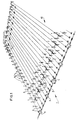
- the device 1 according to the invention as shown in fig. 1 serves to keep a field 10 free from weeds.
- a crop 9 is planted in this field 10 in mutually staggered rows.
- the crop 9 comprises for instance small trees or vegetables.
- each roller 5 is embodied as a cable pulley with a vertical axis of rotation.
- the roller 5 is anchored into the ground by means of a ground pin 14.
- a plate 15 is laid beneath the roller 5 in order to prevent the roller 5 working its way in the course of time into the underlying ground.
- a slide member 7 is connected to the two portions of each cord 6 extending between the shaft 2 and the relevant pair of rollers 5. As shown in fig. 1 these slide members are joined to these cord portions at locations diagonally opposite to each other. It will be apparent that as a result, when the shaft 2 rotates, the two slide members attached to one cord 6 will move in opposite directions from one side of the field to the other. By switching the direction of movement of the drive device 4 the slide members 7 can subsequently move back again.
- the tube forming the rotating shaft 2 has for instance a diameter of 20 mm.
- the slide member At a rotation speed of one revolution per second the slide member then reaches a speed of movement of 225 m per hour. Because of this small speed the power of the drive device 4 can be limited. It has been found that even during very good growing weather it is sufficient to agitate the surface of the ground once a day in order to prevent germinating seeds from taking root. The roots of these germinating seeds are denied the opportunity to establish themselves without hindrance in the ground, so that the germinating seed will eventually die.
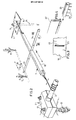
- Fig. 2 shows more clearly how the ground surface is agitated using the embodiment of the device according to the invention described here.
- the slide member 7 comprises a strip-like base part 18 placed on its narrow side and having arms 19 placed half way along the broad sides extending transversely on either side.
- the base part 18 protrudes with a lower edge 20 slightly below the underside of the arms 19. This lower edge 20 acts as a sled gripping in the ground and provides a good guiding of the slide member 7, even when the arms 19 protruding on both sides are unevenly loaded.
- each arm 19 protrudes precisely between a row of plants 9.
- the end of each arm 19 can thus come in contact with the foot of a plant 9 and as the slide member 7 moves forward it brushes past half the periphery of the plant concerned.
- the arm 19 of the slide member 7 arranged on the other side of the row of plants brushes past the other side of the foot of the plants, so that the ground around the row of plants is agitated. In this way the ground can be completely covered by the slide members, so that weeds cannot develop anywhere.
- each slide member can take a relatively stiff form. When it comes into contact with the foot of a plant or small tree 9 or with the arm 19 of the slide member on the other side of the row, the slide member 7 can be knocked slightly out of line or deflect sideways. Owing to the tensile force of the cord 6 however the slide member 7 moves directly back again after passing the obstacle, so that the covering of the ground around the crops as described is ensured.
- each bearing block 3 just as the drive device 4, is mounted using anchors 11 screwed into the ground.
- Each anchor 11 carries on its upper end a screw thread onto which is fitted a nut 12, with which the relevant bearing block 3 is fixed.
- Shown in fig. 1 is that each portion of each cord 6 runs past or through a detector 8 placed close to the shaft 2. These detectors 8 are activated if the cord 6 breaks. Some of these detectors 8 can further be used to determine when the slide members 7 have reached their extreme position close to the shaft 2. Through activation of the detector 8 the driving is then switched off.
- a control device (not further shown) is embodied such that when the device is next switched on the rotation direction of the shaft 2 is reversed, so that the slide members 7 which are situated in their end position close to the shaft 2 are moved back to the other side of the field 10, close to the pairs of guide rollers 5.
- This control device can further be provided with a timer which switches on the device regularly, for example daily.
- a timer which switches on the device regularly, for example daily.
- the interval between two periods of operation can be adapted to the speed of rooting of the germinating seeds, which is determined by the atmosphere at the ground surface. That is, when the weather is dry and hot, the seeds will not or virtually not germinate and take root, so that the intervals between two periods of operation can be prolonged.
- the length of the shaft 2 can amount to about 50 m on either side of the drive device 4. There is hardly any limit to be placed on the distance between the shaft 2 and the pairs of guide rollers 5. That is, the field lengths of a maximum of about 200 m that occur in practice can be covered without any problem.
- Fig. 4 partially shows an arm 22 of a slide member according to a slightly different embodiment of the invention.
- This arm 22 can co-act with a rake element 23 provided with downward protruding teeth.
- This rake element 23 can slide onto the bottom of the arm 22.
- a number of the slide members can be provided with these rake elements 23, so that the relevant piece of ground is automatically raked when the device is in operation.
- the rake elements 23 Prior to a following operational cycle of the device the rake elements 23 can be arranged on other slide members. By raking the ground at determined intervals in this manner, the relevant piece of ground 10 remains well loosened and retains a well-cared for appearance.
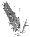
- Fig. 5 shows another device according to the invention for controlling unwanted plant growth on a piece of ground.
- This device 27 consists of two strips of wire mesh 28 laid on the ground. These strips 28 are pivotably connected at their ends to a lever 30 which itself pivots halfway along on a bearing support 29 anchored in the ground, for instance with ground pins. Regular surface agitation of the piece of ground is carried out by moving the strip of wire mesh back and forth over a distance which is at least equal to the length of one mesh in the wire mesh. This movement can be generated using a jack, or as shown schematically in fig. 5, using electromagnets 31. These electromagnets are regularly switched on by a control/power supply device 34, which is provided with energy from a battery 33, which is supplied using a solar panel 32. With an electrical power supply device of this type the device according to the invention can be employed at great distance from the mains electricity supply.
- the electromagnets 31 can be controlled such that the strips of wire mesh 28 are moved one stroke length each time the device is set into operation. It is also possible to supply the electromagnets with an alternating voltage, so that the strips of wire mesh 28 are shaken back and forth for some time.
- the invention can be applied in many different ways.
- the device according to the invention in particular can be embodied in many different ways.
- the only thing of importance thereby is that according to the inventive method the surface of the piece of ground is regularly agitated in order to prevent germinating seeds from taking root. Whether this agitation is performed by moving a slide member over a determined surface as with the above described device 1, or by agitating a relevant surface at one time as with the device 27, is irrelevant.
- a suitable embodiment can be found as circumstances require.
Landscapes
- Life Sciences & Earth Sciences (AREA)
- Engineering & Computer Science (AREA)
- Mechanical Engineering (AREA)
- Environmental Sciences (AREA)
- Soil Sciences (AREA)
- Insects & Arthropods (AREA)
- Pest Control & Pesticides (AREA)
- Wood Science & Technology (AREA)
- Zoology (AREA)
- Catching Or Destruction (AREA)
- Soil Working Implements (AREA)
Applications Claiming Priority (2)
| Application Number | Priority Date | Filing Date | Title |
|---|---|---|---|
| NL8801607A NL8801607A (nl) | 1988-06-23 | 1988-06-23 | Werkwijze en inrichting voor het tegengaan van ongewenste plantengroei op een stuk grond. |
| NL8801607 | 1988-06-23 |
Publications (1)
| Publication Number | Publication Date |
|---|---|
| EP0347982A1 true EP0347982A1 (de) | 1989-12-27 |
Family
ID=19852516
Family Applications (1)
| Application Number | Title | Priority Date | Filing Date |
|---|---|---|---|
| EP89201541A Withdrawn EP0347982A1 (de) | 1988-06-23 | 1989-06-13 | Verfahren und Vorrichtung zur Verhinderung des unerwünschten Wachstums von Pflanzen auf einem Grundstück |
Country Status (2)
| Country | Link |
|---|---|
| EP (1) | EP0347982A1 (de) |
| NL (1) | NL8801607A (de) |
Cited By (2)
| Publication number | Priority date | Publication date | Assignee | Title |
|---|---|---|---|---|
| WO1998020730A1 (en) * | 1996-11-15 | 1998-05-22 | William Pratizzoli | Plant for the controlled diffusion of active substances in cultivation and in defence against parasites in agriculture |
| KR100721425B1 (ko) | 2005-12-26 | 2007-05-23 | 이근배 | 농업용 제초기 |
Citations (3)
| Publication number | Priority date | Publication date | Assignee | Title |
|---|---|---|---|---|
| FR325523A (fr) * | 1902-10-22 | 1903-05-01 | Lubin David | Dispositif pour engendrer un effort moteur |
| FR907549A (fr) * | 1944-10-18 | 1946-03-14 | équipement mécanique agricole | |
| DE1105220B (de) * | 1959-03-13 | 1961-04-20 | Ernst Putfarken | Vorrichtung zum Entfernen und Zerstoeren von Unkraut |
-
1988
- 1988-06-23 NL NL8801607A patent/NL8801607A/nl not_active Application Discontinuation
-
1989
- 1989-06-13 EP EP89201541A patent/EP0347982A1/de not_active Withdrawn
Patent Citations (3)
| Publication number | Priority date | Publication date | Assignee | Title |
|---|---|---|---|---|
| FR325523A (fr) * | 1902-10-22 | 1903-05-01 | Lubin David | Dispositif pour engendrer un effort moteur |
| FR907549A (fr) * | 1944-10-18 | 1946-03-14 | équipement mécanique agricole | |
| DE1105220B (de) * | 1959-03-13 | 1961-04-20 | Ernst Putfarken | Vorrichtung zum Entfernen und Zerstoeren von Unkraut |
Cited By (2)
| Publication number | Priority date | Publication date | Assignee | Title |
|---|---|---|---|---|
| WO1998020730A1 (en) * | 1996-11-15 | 1998-05-22 | William Pratizzoli | Plant for the controlled diffusion of active substances in cultivation and in defence against parasites in agriculture |
| KR100721425B1 (ko) | 2005-12-26 | 2007-05-23 | 이근배 | 농업용 제초기 |
Also Published As
| Publication number | Publication date |
|---|---|
| NL8801607A (nl) | 1990-01-16 |
Similar Documents
| Publication | Publication Date | Title |
|---|---|---|
| US5337514A (en) | Method and apparatus for plant culture | |
| US4261163A (en) | Method and apparatus for harvesting produce on plastic mulch beds | |
| EP0569803A1 (de) | Pflanzmaschine für in Töpfen gezogene Pflanzen | |
| KR20210109414A (ko) | 밭작물의 줄기절단장치 | |
| US6094861A (en) | Vegetable growing apparatus | |
| US6578318B1 (en) | Method and apparatus for raising vine plants | |
| US3546856A (en) | Method of harvesting vine borne crops | |
| US5588494A (en) | Crop inverter and method of using same | |
| EP0347982A1 (de) | Verfahren und Vorrichtung zur Verhinderung des unerwünschten Wachstums von Pflanzen auf einem Grundstück | |
| US4365463A (en) | Harvesting tomatoes | |
| KR102134014B1 (ko) | 농작물 재배용 멀칭매트 천공장치 | |
| US5063708A (en) | Horticultural layout ground cover assembly | |
| JPH0530861A (ja) | 植物の栽培方法と栽培装置 | |
| KR200403145Y1 (ko) | 농업용 고랑제초기 | |
| US3421303A (en) | Bean harvesting attachment for tractors | |
| SU1591877A1 (ru) | Способ ведения виноградных кустов в укрывной зоне | |
| JP3124431U (ja) | 土中ネット敷設装置 | |
| KR102417719B1 (ko) | 멀칭매트의 식생 홀 천공장치 | |
| IL296104A (en) | Vineyard shading system | |
| SU1380660A1 (ru) | Устройство дл обрезки стеблей сельскохоз йственных культур | |
| SU1459638A1 (ru) | Способ ведени виноградных кустов в укрывной зоне | |
| JP3192389B2 (ja) | 玉葱収穫機 | |
| KR100547613B1 (ko) | 버섯 재배장치 | |
| JP2000023558A (ja) | 水耕(養液)栽培においての、軟白ネギ栽培装置及び、その装置を用いた栽培方法 | |
| CN221532156U (zh) | 一种新型多功能薯类杀秧机 |
Legal Events
| Date | Code | Title | Description |
|---|---|---|---|
| PUAI | Public reference made under article 153(3) epc to a published international application that has entered the european phase |
Free format text: ORIGINAL CODE: 0009012 |
|
| AK | Designated contracting states |
Kind code of ref document: A1 Designated state(s): BE DE FR GB LU NL |
|
| 17P | Request for examination filed |
Effective date: 19900514 |
|
| 17Q | First examination report despatched |
Effective date: 19900820 |
|
| STAA | Information on the status of an ep patent application or granted ep patent |
Free format text: STATUS: THE APPLICATION IS DEEMED TO BE WITHDRAWN |
|
| 18D | Application deemed to be withdrawn |
Effective date: 19910716 |