EP0347979A1 - Equipement de surveillance de vitesse d'une moissonneuse-batteuse - Google Patents
Equipement de surveillance de vitesse d'une moissonneuse-batteuse Download PDFInfo
- Publication number
- EP0347979A1 EP0347979A1 EP89201536A EP89201536A EP0347979A1 EP 0347979 A1 EP0347979 A1 EP 0347979A1 EP 89201536 A EP89201536 A EP 89201536A EP 89201536 A EP89201536 A EP 89201536A EP 0347979 A1 EP0347979 A1 EP 0347979A1
- Authority
- EP
- European Patent Office
- Prior art keywords
- grain
- signal
- loss
- grain separation
- separation
- Prior art date
- Legal status (The legal status is an assumption and is not a legal conclusion. Google has not performed a legal analysis and makes no representation as to the accuracy of the status listed.)
- Granted
Links
Images


Classifications
-
- A—HUMAN NECESSITIES
- A01—AGRICULTURE; FORESTRY; ANIMAL HUSBANDRY; HUNTING; TRAPPING; FISHING
- A01D—HARVESTING; MOWING
- A01D41/00—Combines, i.e. harvesters or mowers combined with threshing devices
- A01D41/12—Details of combines
- A01D41/127—Control or measuring arrangements specially adapted for combines
- A01D41/1271—Control or measuring arrangements specially adapted for combines for measuring crop flow
- A01D41/1272—Control or measuring arrangements specially adapted for combines for measuring crop flow for measuring grain flow
- A01D41/1273—Control or measuring arrangements specially adapted for combines for measuring crop flow for measuring grain flow for measuring grain loss
-
- Y—GENERAL TAGGING OF NEW TECHNOLOGICAL DEVELOPMENTS; GENERAL TAGGING OF CROSS-SECTIONAL TECHNOLOGIES SPANNING OVER SEVERAL SECTIONS OF THE IPC; TECHNICAL SUBJECTS COVERED BY FORMER USPC CROSS-REFERENCE ART COLLECTIONS [XRACs] AND DIGESTS
- Y10—TECHNICAL SUBJECTS COVERED BY FORMER USPC
- Y10S—TECHNICAL SUBJECTS COVERED BY FORMER USPC CROSS-REFERENCE ART COLLECTIONS [XRACs] AND DIGESTS
- Y10S56/00—Harvesters
- Y10S56/15—Condition responsive
Definitions
- This invention relates generally to combine harvesters and, more particularly, to such machines fitted with some form of control system operable to adjust the amount of crop material passing through the machine by varying the ground speed of the combine.
- control systems for combine harvesters are to maximize the capacity of the machine and yet minimize grain loss.
- Numerous control systems have been proposed but to date, no system has been commercially adapted for combine harvesters primarily because all systems so far proposed are impracticable in the sense that they do not meet the stated objective in a wholly satisfactory manner.
- the main factor affecting the practicability of combine harvester control systems is that of grain loss.
- a control system which does not take account of grain loss cannot seriously be entertained because grain loss is a highly critical factor in the harvesting operation.
- a control system which does take account of grain loss was suspect up till now in that there was no method of measuring grain loss in absolute terms.
- a problem with utilizing some form of grain loss measurement to effect machine control is however that the control loop is relatively slow because a given volume of crop material takes a finite time (typically 10 seconds in conventional combine harvesters and approximately 5 seconds in rotary combine harvesters) to progress through the machine before the grain loss associated with that volume is measured. With such a slow control loop, the control system can become unstable in that it oscillates or hunts between maximum and minimum control. This problem is also associated with any other parameter of the machine which may be used in the control system and which is related to some crop processing component located in the machine such that there is a significant time delay between crop material entering the machine and reaching that component.
- a combine harvester having an engine, a traction drive transmission, a header, a threshing and separating mechanism and a machine throughput control system comprising a grain loss control loop operable to produce a signal representative of grain loss and including a grain loss controller to which the grain loss signal and a reference grain loss signal are applied, characterized in that the machine throughput control system further comprises a grain separation control loop operable to produce a signal representative of the grain separation in the machine, the grain loss controller is operable continuously to derive a reference grain separation signal from the grain separation signal, the grain loss signal and the reference grain loss signal, and means are provided for algebraically summing the grain separation signal and the reference grain separation signal to produce a grain separation error signal which is used to control the machine throughput.
- the first causal relationship On the one hand, a good relationship has been found between grain separation in a combine and the grain loss while on the other hand also a good relation, more specifically of a linear type, was experienced between the grain separation and the ground speed.
- the relationship between grain separation and grain loss will hereinafter be referred to as "the first causal relationship".
- the grain separation is detected by grain impact sensors as described in the already mention co-pending European applications nrs. 88.200.801.4 and 88.200.803.0 and the grain loss is determined by an algorithm as described in the co-pending European application n° 88.200.802.2.
- Said algorithm is in the form of a formula which calculates the grain loss from signals received from three or more impact detectors placed along the threshing and separating machanism and from sensors for measuring operating condition parameters.
- the algorithm as described in the mentioned European application will not be described here in details, but will further be called a loss algorithm which produces a loss signal.
- the grain separation control loop comprises a sensor operable to measure the grain separation under the rotary separator. This is the most forward place up till now in the threshing and separating mechanism where a grain separation sensor can measure the grain separation over the total width of the combine harvester without being saturated by the amounts of grain which are locally separated.
- the detector is of a construction as described in the co-pending European application n° 88.200.803.0. According to this application, the detector plate member is provided with signal damping means around its periphery which allow a very high detection rate capability. In case techniques would come available, permitting grain separation measurements at still much higher rates, then it would be possible to already measure grain separation totally at the front of the threshing and separating mechanism, namely under the threshing drum.
- the grain separation sensor under the rotary separator moreover forms part of the set of sensors which provide input signals to the mentioned grain loss algorithm and accordingly provides an advantage in that it realises a stable first causal relationship i.e. a stable relationship between the grain separation detected under the rotary separator and the grain loss signal determined by the grain loss algorithm.
- the grain separation control loop further comprises a PID-controller and ground speed control loop to which the output of the PID- controller is connected.
- This ground speed control loop preferably comprises a traction drive transmission and a traction variator and automatically adjusts the ground speed following a set value derived from the output of the PID-controller.
- the grain separation control loop preferably also comprises a grain separation controller which receives output signals from the grain separation sensor and a ground speed signal, via a time delay operable to present the ground speed signal in phase with the grain separation signal.
- the grain separation controller is operable continuously to establish a causal relationship between ground speed and grain separation, with the ground speed signal being applied against that relationship current at that time to derive a corresponding representative grain separation signal.
- this representative grain separation signal is used in lieu of the actual grain separation signal for algebraic summation with the aforementioned reference grain separation signal.
- the relationship between ground speed and grain separation will hereinafter be referred to as "the second causal relationship".
- the grain separation controller preferably comprises a grain separation parameter estimator operable continuously to establish the causal relationship between the ground speed and the grain separation, a grain separation estimator operable to derive an estimated grain separation signal from the ground speed signal and that causal relationship, and a further time delay operable to present the estimated grain separation signal in phase with the measured grain separation signal to first summer means for algebraic summation to produce an error signal.
- the grain separation controller may further comprise second summer means for adding the error signal to the estimated grain separation signal to produce the representative grain separation signal already mentioned.
- the grain loss control loop may comprise, as already mentioned, grain separation sensors providing input to a grain loss algorithm and a grain loss controller, the grain loss controller receiving the output signal from the grain loss algorithm and a signal from the grain separation control loop via a time delay operable to make the grain separation signal in phase with the grain loss signal, and the grain loss controller being operable to establish said causal relationship between grain separation and grain loss, and to derive said reference grain separation signal.
- the grain loss controller comprises a grain loss parameter estimator operable continuously to establish the causal relationship between the machine grain separation signal received via the time delay and the grain loss signal, and a loss estimator operable to derive an estimated loss signal from the grain separation signal and the causal relationship current therewith.
- the grain loss controller may also comprise a further time delay operable to present the estimated loss signal in phase with the measured loss signal, first summer means for algebraically summing the estimated loss signal received from the further time delay and the measured loss signal to produce an error signal, second summer means for adding the error signal to the estimated loss signal to produce a representative loss signal, third summer means for algebraically summing the representative loss signal and the reference loss signal to produce a loss error signal, and convertor means for applying the loss error signal against the causal relationship current at that time to derive therefrom the reference grain separation signal.
- the grain loss controller may comprise a grain loss parameter estimator operable continuously to establish the first causal relationship between the grain separation signal received via the time delay and the grain loss signal received from the loss algorithm, first convertor means for applying the grain loss signal against the causal relationship current at that time to derive therefrom an equivalent grain separation signal, first summer means for algebraically summing the equivalent machine loading signal and the grain separation signal received from the time delay to produce an error signal, second summer means for adding the error signal to the measured grain separation signal to produce a revised grain separation signal, second convertor means for applying the reference loss signal against the first causal relationship current at that time to derive therefrom a corresponding grain separation signal, and third summer means for algebraically summing the corresponding grain separation signal derived from the reference loss signal and the revised grain separation signal to derive therefrom the reference grain separation signal already mentioned.
- first convertor means for applying the grain loss signal against the causal relationship current at that time to derive therefrom an equivalent grain separation signal
- first summer means for algebraically summing the equivalent machine loading signal and the grain separation signal received from the time
- the grain loss controller may comprise shift register means to which the grain separation and grain loss signals are applied, means for establishing the first causal relationship and means for deriving said reference grain separation signal.
- the means for deriving estimated loss signals from machine grain separation signals, and means for establishing the first causal relationship employ a two parameter model, analysis of which may be effected using either the regression analysis or cluster analysis technique.
- the combine harvester generally indicated at 1, comprises a main chassis or frame 2 supported on a front pair of traction wheels 3 and a rear pair of steerable wheels 4. Supported on the main chassis 2 are an operator's platform 5 with a driver's seat 6 and a steering wheel 7, a grain tank 8, a threshing and separating mechanism indicated generally at 9, a grain cleaning mechanism 11 and a conventional engine (not shown).
- the engine provides the motive power for the various driven components of the machine as well as for the traction wheels 3 which are driven via a conventional belt variator (also not shown).
- a conventional header 12 and straw elevator 13 extend forwardly of the main chassis 2 to gather crop material and convey it to the threshing and separating mechanism 9.
- the header 12 is pivotally secured to the chassis 2 for generally vertical movement which is controlled by extensible hydraulic cylinders 14.
- the combine harvester 1 As the combine harvester 1 is propelled forwardly over a field with standing crop, the latter is severed from the stubble by a sickle bar 10 on the header 12, whereafter a reel 15 and a header auger 16 convey the cut crop to the straw elevator 13 which supplies it to the threshing and separating mechanism 9.
- the crop received within the threshing and separating mechanism 9 is threshed and separated that is to say the crop (which may be wheat, corn, rice, soybeans, rye, grass seed, barley, oats or other similar crops) is rubbed and beaten, whereby the grain, seed or the like, is loosened and separated from the straw, stalks, coils or other discardable part of the crop.
- Grain which has been separated from the straw falls onto the grain cleaning mechanism 11 which comprises means to separate chaff and other impurities from the grain, and means to separate unthreshed materials (tailings). Cleaned grain is then elevated into the grain tank 8 and the tailings are reprocessed in separate tailings rethreshers (not shown) and returned to the cleaning mechanism 11 for repeat cleaning action.
- a threshing portion 17 of the threshing and separating mechanism 9 comprises a rotatable threshing cylinder 18 cooperable with a stationary threshing concave 19. Rearwardly of the threshing mechanism 17, a deflector beater, or so-called straw beater, 21 with an associated beater grate is provided.
- the straw beater 21 has a smaller diameter than the threshing cylinder 18 and is arranged above the level of the discharge end of the threshing concave 19.
- the straw beater 21 and beater grate have substantially the same width as the threshing mechanism 17.
- a separator portion of the threshing and separating mechanism 9 comprises a first separator rotor or cylinder 22 and a second rotor or cylinder 23 cooperable with respective concaves 24 and 25.
- the second rotor 23 is mounted within a separator housing 26 and both of these components have a width substantially exceeding the width of the first rotor 22 which is the same width as the beater 21 and the threshing mechanism 17.
- the rotor housing 26 has a width approximately twice that of the rotor 22.
- the mat of crop material received by the separator rotor 23 from the separator rotor 22 is divided into two portions (by means not shown) which are moved spirally around the rotor 23 to respective ends thereof to complete the separating action. On reaching the ends of the rotor 23, the mats of crop material (straw) are propelled by the rotor through respective straw hoods 27 for discharge from the machine.
- the rotary threshing and separating mechanism 9 is only one example of various types of threshing and separating mechanisms know in the art.
- Another embodiment of the present invention may comprise the more conventional straw walker type separator means as a substitute for the separator rotor 23 and associated separator concaves 25.
- the entire threshing and separating mechanism may be of a different type and may comprise one or two "axial flow" threshing and separating rotors cooperable with associated threshing and separating concaves, extending longitudinally of the combine harvester.
- a twin rotor "axial flow” combine of this type is disclosed in more details in GB-A-1.339.601.
- the present invention is applicable on anyone of these type of combine harvesters and is used for controlling the grain losses occurring at the discharge end of either the separating mechanism 9 or the cleaning apparatus 11 or of both said separating mechanism and cleaning apparatus.
- the machine is fitted with a grain separation control system which, in this preferred embodiment is used to control the ground speed of the machine, and is based on the measurement of the grain separation through the concave 24 under the rotary separator 22.
- a grain separation control system which, in this preferred embodiment is used to control the ground speed of the machine, and is based on the measurement of the grain separation through the concave 24 under the rotary separator 22.
- the fast control loop is fine tuned by means of a slower master control loop based on grain loss measurement as now will be described more fully.
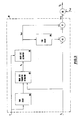
- FIG. 2 of the drawings shows a block diagram useful in explaining the present invention in greater detail, the diagram showing not only the control system ( in full lines) but also certain operational functions and characteristics of the machine (in broken lines).
- the control system comprises in fact four control loops: the grain separator or slave control loop and the grain loss or master control loop already referred to; an engine control loop; and a ground speed control loop.
- a traction drive mechanism is indicated at 31 and is in the form of the belt variator already referred to and which has associated with it the usual hydraulic cylinder and valve operable to vary the diameter of one of the sheaves in order to effect the desired change in speed.
- the revolutions per minute (V) of the output shaft of the traction drive mechanism 31 can be translated into a machine loading characteristic by multiplying by the diameter of the traction wheels 3 and the width of the sickle bar 10 (as indicated at 32) to provide a measure of the area of standing crop being cut per second (m2/sec), and by multiplying the latter by the crop density (as indicated at 33) to provide a measure of the weight of crop material being handled per second (kg/sec).
- This volume of crop material when fed to the threshing and separating mechanism 9, produces a grain separation S in the latter in kg/sec.
- the straw material is finally discharged from the machine as indicated by the arrow 34.
- Measurements of grain separation at different locations along the combine separation area are introduced into a loss algorithm which derives a representative grain loss signal L from the grain separation measurements.
- the loss algorithm referred to is disclosed in co-pending European application n° 88.200.802.2 which disclosure is hereby incorporated by reference and which will provide details of the algorithm which are not directly associated with the present invention.
- the volume of crop material being handled also produces a torque in the combine harvester engine (as indicated at 35) by virtue of the engine having to drive the various crop processing components, and this in turn determines the rotational speed W of the engine (as indicated at 36).
- W the rotational speed of the engine
- this comprises a grain separation detector 37, which may be associated with the grain separation in the threshing and separating mechanism 9 in general, or with the grain separation through the concave 24 in particular.
- the grain separation sensor 37 produces an output signal S1 representative of the grain separation through the concave 24, which may be applied to the negative input terminal of a summer 38.
- a representative grain separation signal S REP derived from the aforementioned signal S1 is applied to the input terminal of the summer 38 to reduce the risk of the grain separation control loop becoming unstable.
- S REP is calculated in the slave loop controller 61 to which are applied on the one hand aforementioned grain separation signal S1 as measured by the grain separation sensor 37 and, on the other hand, the ground speed signal V of the traction drive mechanism 31 as measured by the traction shaft RPM sensor 42.
- the signals S1 and V are applied to the slave loop controller via a smoothing filter 62.
- the ground speed signal V is fed into the grain separation parameter estimator 63 via a time delay 64 in order to obtain the correct phase relationship between that signal V and the grain separation signal S1.
- the relation parameter A1 determined as indicated above, is applied against the measured ground speed signal V in a grain separation estimator 70 to derive therefrom an estimated grain separation signal S EST .
- the estimated grain separation signal S EST is applied via a further time delay 65, which is basically the same as the time delay 64, to the negative input terminal of a summer 66.
- the positive input terminal of the summer 66 receives the grain separation signal S1, and thus the separation signal S1 and the estimated grain separation signal S EST are brought in the correct phase relationship and algebraically summed to define a grain separation error signal.
- This grain separation error signal and the estimated grain separation signal S EST are summed in a further summer 67 to produce a representative grain separation signal S REP , which is thus derived from the measured ground speed V and which is obtained before the corresponding grain separation signal S1 actually can be measured.
- the relation parameter A1 may fluctuate continuously and hence this parameter is continuously being recalculated and applied against the measured speed signals V continuously to derive therefrom S EST values.
- shift registers advantageously can be used.
- the representative grain separation S REP is applied to the negative input terminal of a summer 38 for comparison with a reference grain separation S REF produced by the loss control loop and applied to the positive input terminal of the summer 38.
- the loss control loop and the reference grain separation S REF will be described in greater detail hereafter.
- the output E S of the summer 38 is applied to a priority controller 39, the output of which is applied as a machine separation command signal to a grain separation controller 41 in the form of a PID (proportional-integrator-differentiator) controller and/or an adaptive control algorithm.
- the grain separation controller 41 produces an output signal of a given frequency (pulses per second) which is applied to the ground speed control loop inside the grain separation control loop.
- the output V REQ of the PID controller 41 is applied to the positive input terminal of a summer 43, the negative input terminal of which receives the ground speed signal V from the traction shaft RPM detector 42 via a filter 80 for smoothing the ground speed signal V.
- the output E V of the summer 43 is applied to another PID-controller 81, which in a preferred embodiment is a P-controller with dead zone.
- This controller 81 produces an output signal T of a given duration (seconds) which is applied to the traction drive mechanism 31, in particular the control valve of the belt variator already referred to and driving the traction wheels 3 from the combine harvester engine.
- the rotational output speed of the traction drive mechanism 31 is measured by the sensor 42 and the output V thereof is fed back directly to the summer 43 via the filter 80, as already described, and indirectly to the priority controller 39 via a summer 83 which receives as a second input 69 a reference ground speed signal V REF , the meaning of which will be made apparent hereafter.
- the PID controller 41 further receives an input 68 which is provided by ways of signals representative of certain machine parameters such as, for example, the operational characteristics of the belt variator of the traction drive mechanism 31, the operational relationship between the belt variator and the traction drive mechanism (for example, the time to change the variator from minimum to maximum speed), the ratios of the gearbox associated with the engine, and the oil flow per unit time to the control valve. These signals help to achieve a more accurate grain separation control signal. Additional or alternative parameters may be used.
- the grain separation control loop is designed to accommodate either a hydrostatic traction drive mechanism or the more normal belt variator drive and in the former case the output of the controller 81 is a voltage representative for the output of summer 43, the voltage being applied to a control valve for regulating the oil flow of the hydrostatic pump, whereas in the latter case a "high" (typically 12 volts) T signal, already referred to hereabove, is used to drive the valve associated with the variator. In the latter case, the duration of the T signal is a measure of the change in ground speed required.
- the grain separation loop is enabled if the following conditions are met :
- the grain loss or master control loop includes grain separating sensing means 37, 82 and 44 associated with the grain separation process 9, their respective output signals S1, S2 and S3 being applied, via respective smoothing filters and time delays 62, 45 and 85, to the loss algorithm 84.
- the time delays 62, 45 and 85 are operable to synchronise the outputs of the sensors 37, 82 and 44 positioned at different locations in the separating process. More specifically, sensor 37 is provided under the rotary separator 22 as already mentioned; sensor 44 is the conventional grain loss sensor provided near the discharge end of the separating mechanism 9 while sensor 82 is placed in the separation area between sensors 37 and 44.
- the loss algorithm 84 further receives input signals from other sensor means for measuring operating condition parameters. Those signals, generally indicated at 93, are representative of a.o. the moisture content of the crop being harvested and the flow rate of all material other than grain (i.e. mainly straw).
- the loss algorithm 84 produces a signal L which is representative for the grain loss and which is applied to the grain loss or master loop controller 46. Further direct inputs to the loss controller 46 are the output S1 from the grain separation sensor 37 as well as a reference grain loss signal L REF which is set by the machine operator as is customary. In practice, the operator checks, during a start routine, whether actual grain loss experienced at the rear of the combine is at an acceptable level. Too high losses are, of course, unacceptable because of the amount of grain being lost. Too low losses equally are unacceptable as they mean that the desired maximum combine capacity is not being realized. If actual grain losses experienced correspond to the "desirable" losses, the grain loss signal produced by the grain loss algorithm 84 and corresponding to the actual grain losses, is marked as L REF in the microprocessor and put as such in the memory thereof.
- L REF adjusted downwardly or upwardly, respectively, in an electronic manner by a chosen percentage, without the operator having to check again the actual losses occuring at the rear of the machine in the field.
- the output from the loss controller is in terms of a grain separation reference signal S REF which is applied to the summer 38 along with the representative grain separation signal S REF .
- the output from the summer 38 is an error grain separator signal E S and this is applied to the priority controller 39 as already described.
- the master loop or loss controller 46 is shown in greater details in Figure 4.
- the grain separation signal S1 is applied to a loss parameter estimator 71 via a time delay 47 in order to obtain the correct phase relationship between that signal and the grain loss signal L.
- This is an extremely important aspect of the present invention and is introduced in order to accommodate the time lag discussed above between a given volume of crop material entering the machine and producing a corresponding grain separation signal and the grain loss associated with that grain separation being indicated.
- Another important advandage of the present invention results from the fact that the loss algorithm 84 to determine the grain loss receives input from grain separation detector means comprising the grain separation detector 37, which signal S1 additionally is directly transferred to the slave loop or grain separation controller 61.
- the foregoing arrangement stabilises the relation between the grain separation S1 and the grain loss L and accordingly stabilises the master-slave combination in the total control system.
- the loss controller 46 thus comprises a shift register to which the grain separation and grain loss signals S,L are applied, the output from the register being subjected to regression analysis and parameter estimation at 71 to establish a relationship between grain separation and grain loss.
- the regression analysis is based on a two parameter model rather than a single parameter model and this is another important, although optional, feature of the present invention.
- the relation parameters A and B as used in the above equations, are determined. These relation parameters A and B and the grain separation signal S1 are applied to a loss estimator 51 to derive an estimated loss signal L EST from the measured grain separation signal S1, which signal is representative of the actual loss L which can be expected to occur several seconds later (5 to 10 seconds, depending on the type of combine harvester).
- the estimated loss signal L EST is applied to a time delay 52 which, in essence, is identical to the time delay 47 (provided the microprocessor calculation and shifting times are neglected) and which is operable to present the estimated loss signal L EST in the correct phase relationship with respect to the actual determined loss signal L. Both loss signals are applied in the correct phase relationship to the input terminals of an algebraic summer 58 to produce a loss difference signal.
- the loss difference signal is algebraically added to the estimated loss signal L EST in a further summer 59 to produce a representative loss signal L REP which, in turn, is algebraically compared with the predetermined loss reference signal L REF in another summer 60 to produce a loss error signal E L .
- the loss error signal E L is converted back into an equivalent grain separation signal S EQ in convertor 55 using the relation parameters A and B as defined in the loss parameter estimator 71.
- This equivalent grain separation signal S EQ is finally applied to a PID controller 56 to stabilize and accelerate the control loop reaction.
- the output of the controller is a signal representing a reference grain separation S REF , already referred to, which is applied to the summer 38 as previously described.
- the purpose of the summers 58, 59, 60, the loss parameter estimator 71, and the loss estimator 51 is to reduce the adverse influence of the long process loop time on the stability of the control system. Indeed, there is a considerable loop time between the grain separation S1 and the corresponding loss signal L as has already been explained. Accordingly, it is very important to be able to use in the control system an estimated loss signal L EST in lieu of the actual loss lignal L, which becomes available at too late a point in the loop to be useful. Actually, the estimated loss signal L EST is used in the control system before the actual corresponding losses occur. Obviously, the estimated loss signal L EST should be as close as possible to the actual loss signal L as is accomplished by the various steps as defined above.
- the cluster analysis method may be employed which reduces the number of calculations required but still provides the required relationship between machine grain separation S1 and grain loss which must be established in accordance with the present invention.
- this relationship is updated every five seconds, simultaneously with the production of S REF .
- the operational frequency of the slave grain separation control loop may be faster than the grain loss control loop.
- the basic data such as W and V is "read" every 0.1 seconds.
- the loss controller 46 serves to establish the first causal relationship between grain separation and grain loss, each grain separation signal S1 being applied against that relationship to provide a corresponding estimated grain loss signal from which is derived, as described above, a reference grain separation signal S REF . It will be appreciated that the grain separation/grain loss relationship established here takes account of the loss algorithm.
- the engine control loop comprises a sensor 53 operable to sense the rotational speed W of the output shaft of the engine of the combine harvester, the output of the sensor being applied as one input to a summer 54 which receives a predeteremined reference signal W REF as a second input.
- the difference between these two inputs to the summer 54 is fed as an error signal E W to the priority controller 39, which applies the error signal E W to the PID controller 41 which in turn derives therefrom a signal representative of the required ground speed V REQ in an identical manner as with the error signal E S from the grain separation control loop as already described.
- RPM of shafts other than the engine shaft can be chosen as input for this control loop, in particular the RPM of a main shaft which is representative of the regime behaviour of the combine mechanism drive, this in lieu of the engine shaft RPM.
- the ground speed control loop comprises, as already explained, a summer 43 which processes the required ground speed signal V REQ and the actual ground speed signal V and which derives therefrom the ground speed error signal E V which is used under certain conditions to control the ground speed.
- Another ground speed error signal E V is applied to the priority controller 39 via the summer 83, the negative terminal of which receives the actual ground speed signal V via filter 80, while a reference ground speed signal V REF , already mentioned but still to be described in further detail hereinafter, is fed to the positive input terminal thereof.
- the latter ground speed error signal E V is transferred via the priority controller 39 to the PID controller 41, provided that priority is given by the controller 39.
- the priority controller 39 is also provided with a grain loss error signal E C from the cleaning shoe grain loss sensing means (not shown) which produces a grain loss signal 86 representative of the grain loss measured at the discharge end of the cleaning shoe.
- a preset maximum grain loss value 89 is fed to the positive terminal of the summer 87, while the actual grain loss signal 86 is connected to the negative terminal thereof, the summer 87 producing via an algebraic summation, the error signal E C , representative of the grain loss above the preset maximum.
- the priority controller is provided with a header auger torque error signal E T from the auger torque sensing means (not shown) which produces a signal 92 representative of the crop intake in the machine.
- Torque measurements in components of the combine harvester other than the header auger equally may be used for establishing the level of crop intake.
- the signal 92 is fed to the negative terminal of a summer 90, while a preset maximum signal value 91 is fed to the positive terminal of the summer 90, which produces, via an algebraic summation, the error signal E T , representative of the overload sensed in the header auger.
- the priority controller moreover is provided with a grain separation error signal E S1 .
- This error signal E S1 is produced by a summer 88 via algebraic summing of the grain separation sensing signal S1 fed at its negative terminal and a preset minimum value for the grain separation sensing signal at its positive terminal, this in order to give input to the priority controller 39 in case no grain separation takes place.
- the mentioned error signals E S1 , E S , E C and E T are used to render the priority controller 39 partly inoperative following the setting of priorities, the order of which can be changed, and which are dependent of crop related condition signals, such as separation, and some other input signals to be explained hereafter, which are representative of the priority mode to be applicated.
- the priority controller 39 is provided in order to introduce safeguards into the control system. In addition to the already mentioned input signals, it also receives input signals representative of the header mode, the clutch mode and the operator's mode.
- header mode is meant whether the header 12 is in the lowered, operative position of Figure 1, or the raised, inoperative position and by “clutch mode” is meant whether the clutch associated with the traction drive mechanism is operative or inoperative.
- operator's mode is meant whether the operator is claiming priority over the automatic control system for manual intervention, or whether the automatic control system is controlling the operation of the machine.
- Still further inputs to the priority controller 39 are a time delay and a minimum ground speed, these inputs being predetermined.
- the time delay is used to allow S REF to be established only after the predetermined delay following the enabling of the grain separation control loop. This avoids the loss control loop functioning during a transient period when the grain loss is not stabilized.
- First overriding priority is given to the operator in the event he wants manually to intervene in the operation. Under this condition of manual intervention, the electronic circuitry remains operative as far as measuring, calculating and memorizing are concerned. Only the actuation of the traction drive adjusting mechanism by the electronic circuitry is interrupted as such actuation is done manually at that moment. Second overriding priority is given to an ON/OFF switch. If the switch is on "OFF”, the electronic circuitry again continues to measure, calculate and memorize. However, actuation of the traction drive adjusting mechanism by the electronic circuitry is excluded.
- the reference signal W REF is set to represent the engine speed when the machine is empty and this is compared with the actual speed W and if the difference (E W ) exceeds a predetermined value, the priority controller 39 effectively renders all of the other control loops inoperative.
- the E W signal produces, in this circumstance, an output signal from the priority controller 39 which reduces the ground speed of the machine and this signal is maintained for as long as E W exceeds the predetermined value.
- Fourth overriding priority is given to the grain loss error signal E C from the cleaning shoe on the basis that, if, for whatever reason, the grain loss error signal E C becomes a negative value for a preset minimum period of time in the order of seconds, the priority controller 39 renders all of the other control loops partly inoperative in as much as the electronic circuitry continues to detect, memorize and calculate, but the actuation of the traction drive adjusting mechanism by the electronic circuitry of the other control loops is excluded.
- the error signal E C is fed to the PID controller which reduces the ground speed of the machine in accordance with the error signal received, until the error E C again is positive for a certain time.
- the auger torque error signal E T which comparable to the cleaning grain loss error signal E C , renders all the other controll loops partly inoperative.
- the error signal E T is fed to the PID controller 41 which reduces, in a similar manner as described just before, the ground speed of the machine to decrease the header auger torque until the value of the error E T again is positive for a certain time.
- the grain separation and grain loss control loops are rendered completely inoperative if the header 12 is raised to the inoperative position because crop material is then no longer taken into the machine so that the grain separation and grain loss will decrease further with the result that a higher ground speed would be commanded which would be inappropriate.
- de-actuation of the engine clutch also renders the grain separation and grain loss loops ineffective, otherwise again an inappropriate increase in ground speed would be commanded.
- a too low level of grain separation detected by sensor 37 also renders the grain separation and grain loss loops ineffective because, for some reason, there is no material taken into the machine. This happens when the grain separation error signal E S1 becomes positive.
- the ground speed control loop has an important function when it comes to manipulating the machine at the end of a run in preparation for the next run or pass.
- the machine comes to the so-called headland and runs out the standing crop, the operator normally lifts the header 12.
- the grain separation and grain loss loops are rendered inoperative, as already explained, and in this circumstance the operator can freely manoeuvre the machine.
- the machine is accelerated whilst turning on the headland and approaching the standing crop in preparation for the next run.
- the machine speed exceeds the normal operating speed.
- the machine is empty, whereby the grain separation is low and no losses are measured.
- the control system would command an even higher speed as soon as the header is lowered to the operative position, thereby re-enabling the grain separation and grain loss loops. This continues even as the machine is actually entering the standing crop as indeed, grain separation builds up only with a certain time delay and losses occur after an even longer time delay. In reality, however, ground speed should often be reduced substantially and if it is not then eventually this may result in complete plugging of the machine.
- the clutch is de-activated, or the ground speed or grain separation is below the preset minimum, the entire control system remains inoperative and the operator can freely manoeuvre the machine whilst V REF is kept in the memory.
- the speed control loop is enabled, provided the grain separation S1 is below the minimum value.
- the ground speed error signal E V derived from the actual ground speed V and the reference ground speed V REF is used to control the ground speed, whereby a ground speed similar to that pertaining when the machine reached the headland will be implemented.
- the grain separation control loop is enabled and the control system operates in the manner described.
- the loss control loop is enabled only after the expiration of a preset period of time following the enabling of the grain separation control loop. This avoids the loss control loop functioning and producing corrective actions, during a transient period needed for the grain losses to stabilize.
- an S REF value which was calculated at the end of the next preceding normal operating condition and memorized in the microprocessor, is applied to the positive input terminal of the summer 38 for enabling the grain separation controller loop for proper operation.
- the use of the grain separation in the slave loop of the control system is preferred because the crop characteristics, weather conditions and machine adjustments which influence the grain loss also directly influence the grain separation in the same sense. This makes the relation between the grain separation and the grain loss algorithm, receiving input for grain separation measurements, and thus the control loop stable and hence fast, because the grain separation detector 37 is placed as close as possible to the front of the separating mechanism.
- Machine loading in general could provide an indication of grain loss on the basis that the more heavily the machine is loaded, the greater the grain loss is likely to be, although this is not necessarily so.
- Machine loading can be monitored in various ways, such as by sickle bar power consumption (although this would be undesirable as the cutting heigth and knife sharpness would introduce inaccuracies), the displacement of the undershaft of the straw elevator 13, power consumption or torque in the threshing and separating components, or engine power or torque or contactless microwave crop density measurement in front of the header, or torque in the transportation components in the header and between the header and the threshing and separating components. All those inputs give a tremendous variation in their relation with grain loss in varying crop characteristics, weather conditions and machine adjustments, and as such can not be relied upon for effectively controlling the combine grain loss.
- Grain separation monitoring on the other hand is preferred because of the resulting fast control loop which can be used universally in various crop conditions as the relation between grain separation and grain loss is quite stable, providing a universal stability of the control system.
- the control system can be applied to as well the conventional walker type combines as the rotary type machines and with all type of headers such as grain headers and corn headers, for example.
- the preferred embodiment gives rise to a very practicable control system.
- the refinement afforded by the ground speed control loop is especially welcome in that if the operator attempts to re-enter the standing crop at too high a speed, the speed control loop will command a lower speed (based on that previously pertaining) and hence avoid machine plugging. Equally, the top priority given to the engine control loop avoids plugging.
- the control system reduces operational costs since it reduces, if not obviates, the incidence of machine plugging and maintains grain loss substantially constant with respect to the level of grain loss set by the operator. Also operator fatigue is reduced since many of the checking, controlling and adjusting functions previously attended to by the operator are now carried out by the automatic control system.
- the loss controller 46 of Figure 5 also comprises a shift register to which the grain separation and grain loss signals S1, L are applied, the output from the register being subjected to regression analysis and parameter estimation at 71 to establish a relationship between grain separation S1 and grain loss. Again, a time delay 47 is provided for presenting the grain separation signal S1 in correct phase relationship with the loss signal L to the loss parameter estimator 71.
- the parameters A and B defined in the estimator 71 are used in the convertor 74 to convert the loss signal L to an equivalent grain separation signal S EQ .
- This equivalent grain separation signal S EQ is algebraically summed in the summer 75 with the corresponding, i.e. delayed, grain separation signal S1 to produce a grain separation error signal at the output thereof.
- the grain separation error signal is algebraically added to the grain separation signal S1 (not delayed) in the summer 76 to produce a revised grain separation signal S REV .
- a predetermined loss reference signal L REF converted into a corresponding grain separation reference signal S COR which is fed to the positive input terminal of yet another summer 77 for comparison with the revised grain separation signal S REV which is applied to the negative input terminal of that summer.
- the output of the summer 77 is a grain separation error signal which is fed to the PID controller 56 to stabilize and accelerate the control loop reaction and to produce the reference grain separation signal S REF which is applied to the summer 38 as already described.
Landscapes
- Life Sciences & Earth Sciences (AREA)
- Environmental Sciences (AREA)
- Threshing Machine Elements (AREA)
Applications Claiming Priority (2)
| Application Number | Priority Date | Filing Date | Title |
|---|---|---|---|
| GB888814936A GB8814936D0 (en) | 1988-06-23 | 1988-06-23 | Combine ground speed control system |
| GB8814936 | 1988-06-23 |
Publications (2)
| Publication Number | Publication Date |
|---|---|
| EP0347979A1 true EP0347979A1 (fr) | 1989-12-27 |
| EP0347979B1 EP0347979B1 (fr) | 1993-10-06 |
Family
ID=10639206
Family Applications (1)
| Application Number | Title | Priority Date | Filing Date |
|---|---|---|---|
| EP89201536A Expired - Lifetime EP0347979B1 (fr) | 1988-06-23 | 1989-06-14 | Equipement de surveillance de vitesse d'une moissonneuse-batteuse |
Country Status (5)
| Country | Link |
|---|---|
| US (1) | US4934985A (fr) |
| EP (1) | EP0347979B1 (fr) |
| CA (1) | CA1330113C (fr) |
| DE (1) | DE68909689T2 (fr) |
| GB (1) | GB8814936D0 (fr) |
Cited By (7)
| Publication number | Priority date | Publication date | Assignee | Title |
|---|---|---|---|---|
| EP0479190A1 (fr) * | 1990-10-05 | 1992-04-08 | Deere & Company | Machine de récolte, spécifiquement presse à balles rondes |
| EP1321023A1 (fr) * | 2001-12-18 | 2003-06-25 | CLAAS Selbstfahrende Erntemaschinen GmbH | Procédé de determination des pertes dans des machines agricoles |
| EP2057880A2 (fr) | 2007-11-08 | 2009-05-13 | CNH Belgium N.V. | Appareil et procédé de contrôle de la vitesse d'une moissonneuse agricole |
| EP1900272B1 (fr) * | 2006-09-15 | 2011-12-28 | CLAAS Selbstfahrende Erntemaschinen GmbH | Machine de travail agricole |
| EP3146830A1 (fr) * | 2015-09-23 | 2017-03-29 | Deere & Company | Presentation de consommation de puissance de sous-système sur une machine agricole |
| EP3315003A1 (fr) * | 2016-10-31 | 2018-05-02 | Deere & Company | Commande d'un véhicule agricole basée sur des variables détectées filtrées par différents filtres |
| US20200260646A1 (en) * | 2019-02-20 | 2020-08-20 | Cnh Industrial America Llc | Agricultural Vehicle with Adjustable Maximum Speed Resolution |
Families Citing this family (38)
| Publication number | Priority date | Publication date | Assignee | Title |
|---|---|---|---|---|
| US5019983A (en) * | 1989-02-21 | 1991-05-28 | Eaton Corporation | Automatic steering apparatus using reflected signals |
| AU658066B2 (en) * | 1992-09-10 | 1995-03-30 | Deere & Company | Neural network based control system |
| DE19506059A1 (de) * | 1995-02-22 | 1996-08-29 | Deere & Co | Verfahren zur automatischen Regelung wenigstens eines Abschnitts der Gutbearbeitung in einer Erntemaschine |
| US5860480A (en) * | 1997-04-08 | 1999-01-19 | Caterpillar Inc. | Method and apparatus for determining pitch and ground speed of an earth moving machines |
| US5995895A (en) * | 1997-07-15 | 1999-11-30 | Case Corporation | Control of vehicular systems in response to anticipated conditions predicted using predetermined geo-referenced maps |
| US5878557A (en) * | 1998-04-13 | 1999-03-09 | Deere & Company | Derating the engine of a combine in response to usage |
| US6068059A (en) * | 1998-05-28 | 2000-05-30 | Recot, Inc. | Ground-crop harvester control system |
| US6213870B1 (en) | 1999-03-24 | 2001-04-10 | Caterpillar Inc. | Stall prevention system |
| US6119442A (en) * | 1999-05-14 | 2000-09-19 | Case Corporation | Combine setting autoadjust with machine vision |
| US6397571B1 (en) * | 2001-02-14 | 2002-06-04 | Deere & Company | Combine engine output controlled by harvesting assembly |
| US6475081B2 (en) | 2001-03-20 | 2002-11-05 | Deere & Company | Throughput control for combines having a variable torque sensing drive |
| US6487836B1 (en) | 2001-03-20 | 2002-12-03 | Deere & Company | Crop moisture sensor for controlling harvesting speed |
| US6951514B1 (en) | 2001-03-20 | 2005-10-04 | Deere & Company | Throughput control for combines using feederhouse signal |
| US6553300B2 (en) * | 2001-07-16 | 2003-04-22 | Deere & Company | Harvester with intelligent hybrid control system |
| US6591591B2 (en) * | 2001-07-30 | 2003-07-15 | Deere & Company | Harvester speed control with header position input |
| US6592453B2 (en) * | 2001-09-27 | 2003-07-15 | Deere & Company | Harvester feedrate control with tilt compensation |
| DE10307705A1 (de) * | 2003-02-21 | 2004-09-16 | Claas Selbstfahrende Erntemaschinen Gmbh | Verfahren und Vorrichtung zum Trennen eines Erntegutstroms |
| US20060185340A1 (en) * | 2003-05-19 | 2006-08-24 | Eyre Robert J | Cutting and threshing header for harvesting machine |
| US7261632B2 (en) * | 2004-06-21 | 2007-08-28 | Deere & Company | Self-propelled harvesting machine |
| US7367880B2 (en) * | 2004-07-08 | 2008-05-06 | Battelle Energy Alliance, Llc | Method and apparatus for monitoring characteristics of a flow path having solid components flowing therethrough |
| DE102004059543A1 (de) * | 2004-12-09 | 2006-06-29 | Claas Selbstfahrende Erntemaschinen Gmbh | Landwirtschaftliche Arbeitsmaschine |
| DE102005026159A1 (de) * | 2005-06-06 | 2007-01-25 | Claas Selbstfahrende Erntemaschinen Gmbh | Verfahren zur Steuerung einer Erntemaschine |
| GB0604860D0 (en) * | 2006-03-10 | 2006-04-19 | Cnh Belgium Nv | Improvements in or relating to material stream sensors |
| US8793002B2 (en) * | 2008-06-20 | 2014-07-29 | Caterpillar Inc. | Torque load control system and method |
| US7795752B2 (en) | 2007-11-30 | 2010-09-14 | Caterpillar Inc | System and method for integrated power control |
| US8058829B2 (en) | 2008-11-25 | 2011-11-15 | Caterpillar Inc. | Machine control system and method |
| US8543295B2 (en) | 2010-11-30 | 2013-09-24 | Christian Stanton Carver Bryant | Electronically controlled speed limiting system for turf care machine |
| US8540048B2 (en) | 2011-12-28 | 2013-09-24 | Caterpillar Inc. | System and method for controlling transmission based on variable pressure limit |
| US8968064B2 (en) | 2013-01-23 | 2015-03-03 | Ronald J. Kile | Agricultural combine harvester with harvesting and winnowing optimization control system |
| US9345197B2 (en) * | 2013-05-10 | 2016-05-24 | Agco Corporation | Combine harvester with even crop distribution |
| EP2805603B1 (fr) * | 2013-05-22 | 2017-01-11 | CLAAS E-Systems KGaA mbH & Co KG | Dispositif et procédé de surveillance du tranchant d'une lame |
| US9445546B2 (en) | 2013-12-05 | 2016-09-20 | Agco Corporation | Shoe load and distribution sensing for combine harvester |
| US9901031B2 (en) * | 2014-09-24 | 2018-02-27 | Deere & Company | Automatic tuning of an intelligent combine |
| US9934538B2 (en) | 2014-09-24 | 2018-04-03 | Deere & Company | Recalling crop-specific performance targets for controlling a mobile machine |
| EP3114919B1 (fr) * | 2015-07-08 | 2020-10-28 | Zürn Harvesting GmbH & Co. KG | Systeme de tête de coupe |
| US10729065B2 (en) * | 2015-09-10 | 2020-08-04 | Deere & Company | Augmented crop loss sensing |
| US10064333B2 (en) | 2016-02-11 | 2018-09-04 | Cnh Industrial America Llc | Control method and apparatus for a rotor cage with actuated cage vanes in a harvester |
| US10849272B2 (en) * | 2018-10-02 | 2020-12-01 | Indústrias Reunidas Colombo Ltda | Grain harvesting implement |
Citations (3)
| Publication number | Priority date | Publication date | Assignee | Title |
|---|---|---|---|---|
| US4130980A (en) * | 1977-01-06 | 1978-12-26 | International Harvester Company | Combine automatic travel control system |
| EP0077667A1 (fr) * | 1981-10-21 | 1983-04-27 | Tecalemit Electronics Limited | Appareillage de contrôle pour une moissonneuse-batteuse |
| EP0122343A1 (fr) * | 1983-04-15 | 1984-10-24 | Ford New Holland N.V. | Moissonneuse-batteuse |
Family Cites Families (2)
| Publication number | Priority date | Publication date | Assignee | Title |
|---|---|---|---|---|
| US3515144A (en) * | 1967-07-19 | 1970-06-02 | Deere & Co | Device for sensing operating conditions in a harvesting machine |
| GB1280464A (en) * | 1968-10-04 | 1972-07-05 | Ransomes Sims & Jefferies Ltd | Improvements in or relating to combine harvesters |
-
1988
- 1988-06-23 GB GB888814936A patent/GB8814936D0/en active Pending
-
1989
- 1989-06-14 US US07/366,056 patent/US4934985A/en not_active Expired - Fee Related
- 1989-06-14 DE DE89201536T patent/DE68909689T2/de not_active Expired - Lifetime
- 1989-06-14 EP EP89201536A patent/EP0347979B1/fr not_active Expired - Lifetime
- 1989-06-19 CA CA000603245A patent/CA1330113C/fr not_active Expired - Lifetime
Patent Citations (4)
| Publication number | Priority date | Publication date | Assignee | Title |
|---|---|---|---|---|
| US4130980A (en) * | 1977-01-06 | 1978-12-26 | International Harvester Company | Combine automatic travel control system |
| EP0077667A1 (fr) * | 1981-10-21 | 1983-04-27 | Tecalemit Electronics Limited | Appareillage de contrôle pour une moissonneuse-batteuse |
| GB2107562A (en) * | 1981-10-21 | 1983-05-05 | Tecalemit Electronics Ltd | Control apparatus for a combine harvester |
| EP0122343A1 (fr) * | 1983-04-15 | 1984-10-24 | Ford New Holland N.V. | Moissonneuse-batteuse |
Cited By (12)
| Publication number | Priority date | Publication date | Assignee | Title |
|---|---|---|---|---|
| EP0479190A1 (fr) * | 1990-10-05 | 1992-04-08 | Deere & Company | Machine de récolte, spécifiquement presse à balles rondes |
| EP1321023A1 (fr) * | 2001-12-18 | 2003-06-25 | CLAAS Selbstfahrende Erntemaschinen GmbH | Procédé de determination des pertes dans des machines agricoles |
| EP1900272B1 (fr) * | 2006-09-15 | 2011-12-28 | CLAAS Selbstfahrende Erntemaschinen GmbH | Machine de travail agricole |
| EP2057880A2 (fr) | 2007-11-08 | 2009-05-13 | CNH Belgium N.V. | Appareil et procédé de contrôle de la vitesse d'une moissonneuse agricole |
| EP2057880A3 (fr) * | 2007-11-08 | 2009-12-09 | CNH Belgium N.V. | Appareil et procédé de contrôle de la vitesse d'une moissonneuse agricole |
| EP2319290A1 (fr) * | 2007-11-08 | 2011-05-11 | CNH Belgium N.V. | Moissonneuse batteuse avec appareil de contrôle de la vitesse |
| EP3146830A1 (fr) * | 2015-09-23 | 2017-03-29 | Deere & Company | Presentation de consommation de puissance de sous-système sur une machine agricole |
| US10481628B2 (en) | 2015-09-23 | 2019-11-19 | Deere & Company | Surfacing of subsystem power consumption on an agricultural machine |
| EP3315003A1 (fr) * | 2016-10-31 | 2018-05-02 | Deere & Company | Commande d'un véhicule agricole basée sur des variables détectées filtrées par différents filtres |
| US9961831B1 (en) | 2016-10-31 | 2018-05-08 | Deere & Company | Controlling a mobile machine based on sensed variables filtered with different filters |
| US20200260646A1 (en) * | 2019-02-20 | 2020-08-20 | Cnh Industrial America Llc | Agricultural Vehicle with Adjustable Maximum Speed Resolution |
| US11665998B2 (en) * | 2019-02-20 | 2023-06-06 | Cnh Industrial America Llc | Agricultural vehicle with adjustable maximum speed resolution |
Also Published As
| Publication number | Publication date |
|---|---|
| DE68909689T2 (de) | 1994-03-31 |
| EP0347979B1 (fr) | 1993-10-06 |
| US4934985A (en) | 1990-06-19 |
| DE68909689D1 (de) | 1993-11-11 |
| CA1330113C (fr) | 1994-06-07 |
| GB8814936D0 (en) | 1988-07-27 |
Similar Documents
| Publication | Publication Date | Title |
|---|---|---|
| EP0347979B1 (fr) | Equipement de surveillance de vitesse d'une moissonneuse-batteuse | |
| US4513562A (en) | Combine ground speed control system | |
| US6315658B1 (en) | Arrangement for the control of the forward propulsion speed of a harvesting machine with fuzzy logic | |
| US7921626B2 (en) | Apparatus and method for controlling the speed of a combine harvester | |
| EP3456174B1 (fr) | Procédé et système permettant de contrôler la hauteur d'un outil agricole par rapport au sol | |
| EP3001890B1 (fr) | Syntonisation automatique d'un combiné intelligent | |
| US6726559B2 (en) | Harvester with control system considering operator feedback | |
| EP3675620B1 (fr) | Procédé et système de commande de la hauteur d'un outil agricole par rapport au sol | |
| CA2396321C (fr) | Commande de vitesse d'avance de moissonneuse asservie a l'angle d'inclinaison | |
| CA2383197C (fr) | Regulation de vitesse d'une recolteuse avec signal d'entree de position de la tete de coupe | |
| US5873227A (en) | Combine harvester rotor speed control and control method | |
| CA2383201C (fr) | Moissonneur a systeme de commande hybride intelligent | |
| EP3569050B1 (fr) | Procédé et système permettant de contrôler la hauteur d'un outil agricole par rapport au sol | |
| US20140338298A1 (en) | Harvester with predictive ground speed regulation | |
| EP3476199B1 (fr) | Régulateur de glissement pour convoyeurs latéraux d'une tête de coupe de machine de récolte | |
| WO1987004894A1 (fr) | Installation de traitement de recoltes | |
| US11612102B2 (en) | Drive system for a harvester | |
| EP3714674B1 (fr) | Surveillance de la charge d'un secoueur de paille | |
| EP0914764A1 (fr) | ContrÔle de vitesse du rotor-batteur d'une moissonneuse-batteuse et procédé de contrÔle | |
| JPH08275645A (ja) | コンバインのセカンドモア昇降制御装置 | |
| JPS6344330B2 (fr) |
Legal Events
| Date | Code | Title | Description |
|---|---|---|---|
| PUAI | Public reference made under article 153(3) epc to a published international application that has entered the european phase |
Free format text: ORIGINAL CODE: 0009012 |
|
| 17P | Request for examination filed |
Effective date: 19890614 |
|
| AK | Designated contracting states |
Kind code of ref document: A1 Designated state(s): DE FR GB IT |
|
| 17Q | First examination report despatched |
Effective date: 19910806 |
|
| RAP1 | Party data changed (applicant data changed or rights of an application transferred) |
Owner name: NEW HOLLAND BELGIUM N.V. |
|
| GRAA | (expected) grant |
Free format text: ORIGINAL CODE: 0009210 |
|
| AK | Designated contracting states |
Kind code of ref document: B1 Designated state(s): DE FR GB IT |
|
| PG25 | Lapsed in a contracting state [announced via postgrant information from national office to epo] |
Ref country code: IT Free format text: LAPSE BECAUSE OF FAILURE TO SUBMIT A TRANSLATION OF THE DESCRIPTION OR TO PAY THE FEE WITHIN THE PRE;WARNING: LAPSES OF ITALIAN PATENTS WITH EFFECTIVE DATE BEFORE 2007 MAY HAVE OCCURRED AT ANY TIME BEFORE 2007. THE CORRECT EFFECTIVE DATE MAY BE DIFFERENT FROM THE ONE RECORDED.SCRIBED TIME-LIMIT Effective date: 19931006 |
|
| REF | Corresponds to: |
Ref document number: 68909689 Country of ref document: DE Date of ref document: 19931111 |
|
| ET | Fr: translation filed | ||
| PLBE | No opposition filed within time limit |
Free format text: ORIGINAL CODE: 0009261 |
|
| STAA | Information on the status of an ep patent application or granted ep patent |
Free format text: STATUS: NO OPPOSITION FILED WITHIN TIME LIMIT |
|
| 26N | No opposition filed | ||
| REG | Reference to a national code |
Ref country code: GB Ref legal event code: IF02 |
|
| REG | Reference to a national code |
Ref country code: FR Ref legal event code: CD |
|
| PGFP | Annual fee paid to national office [announced via postgrant information from national office to epo] |
Ref country code: DE Payment date: 20080415 Year of fee payment: 20 |
|
| PGFP | Annual fee paid to national office [announced via postgrant information from national office to epo] |
Ref country code: FR Payment date: 20080407 Year of fee payment: 20 |
|
| PGFP | Annual fee paid to national office [announced via postgrant information from national office to epo] |
Ref country code: GB Payment date: 20080410 Year of fee payment: 20 |
|
| REG | Reference to a national code |
Ref country code: GB Ref legal event code: PE20 Expiry date: 20090613 |
|
| PG25 | Lapsed in a contracting state [announced via postgrant information from national office to epo] |
Ref country code: GB Free format text: LAPSE BECAUSE OF EXPIRATION OF PROTECTION Effective date: 20090613 |