EP0347977A1 - Pneumatisches Stellglied mit elektromagnetischen Steuerventilen - Google Patents
Pneumatisches Stellglied mit elektromagnetischen Steuerventilen Download PDFInfo
- Publication number
- EP0347977A1 EP0347977A1 EP89201534A EP89201534A EP0347977A1 EP 0347977 A1 EP0347977 A1 EP 0347977A1 EP 89201534 A EP89201534 A EP 89201534A EP 89201534 A EP89201534 A EP 89201534A EP 0347977 A1 EP0347977 A1 EP 0347977A1
- Authority
- EP
- European Patent Office
- Prior art keywords
- piston
- air
- valve
- control valves
- positions
- Prior art date
- Legal status (The legal status is an assumption and is not a legal conclusion. Google has not performed a legal analysis and makes no representation as to the accuracy of the status listed.)
- Ceased
Links
Images


Classifications
-
- F—MECHANICAL ENGINEERING; LIGHTING; HEATING; WEAPONS; BLASTING
- F01—MACHINES OR ENGINES IN GENERAL; ENGINE PLANTS IN GENERAL; STEAM ENGINES
- F01L—CYCLICALLY OPERATING VALVES FOR MACHINES OR ENGINES
- F01L9/00—Valve-gear or valve arrangements actuated non-mechanically
- F01L9/10—Valve-gear or valve arrangements actuated non-mechanically by fluid means, e.g. hydraulic
- F01L9/16—Pneumatic means
-
- F—MECHANICAL ENGINEERING; LIGHTING; HEATING; WEAPONS; BLASTING
- F15—FLUID-PRESSURE ACTUATORS; HYDRAULICS OR PNEUMATICS IN GENERAL
- F15B—SYSTEMS ACTING BY MEANS OF FLUIDS IN GENERAL; FLUID-PRESSURE ACTUATORS, e.g. SERVOMOTORS; DETAILS OF FLUID-PRESSURE SYSTEMS, NOT OTHERWISE PROVIDED FOR
- F15B7/00—Systems in which the movement produced is definitely related to the output of a volumetric pump; Telemotors
- F15B7/04—In which the ratio between pump stroke and motor stroke varies with the resistance against the motor
-
- F—MECHANICAL ENGINEERING; LIGHTING; HEATING; WEAPONS; BLASTING
- F01—MACHINES OR ENGINES IN GENERAL; ENGINE PLANTS IN GENERAL; STEAM ENGINES
- F01L—CYCLICALLY OPERATING VALVES FOR MACHINES OR ENGINES
- F01L9/00—Valve-gear or valve arrangements actuated non-mechanically
- F01L9/20—Valve-gear or valve arrangements actuated non-mechanically by electric means
-
- Y—GENERAL TAGGING OF NEW TECHNOLOGICAL DEVELOPMENTS; GENERAL TAGGING OF CROSS-SECTIONAL TECHNOLOGIES SPANNING OVER SEVERAL SECTIONS OF THE IPC; TECHNICAL SUBJECTS COVERED BY FORMER USPC CROSS-REFERENCE ART COLLECTIONS [XRACs] AND DIGESTS
- Y10—TECHNICAL SUBJECTS COVERED BY FORMER USPC
- Y10T—TECHNICAL SUBJECTS COVERED BY FORMER US CLASSIFICATION
- Y10T137/00—Fluid handling
- Y10T137/8593—Systems
- Y10T137/86493—Multi-way valve unit
- Y10T137/86574—Supply and exhaust
- Y10T137/86582—Pilot-actuated
- Y10T137/86614—Electric
Definitions
- the present invention relates generally to a two position, straight line motion actuator and more particularly to a fast acting actuator which utilizes pneumatic energy against a piston to perform fast transit times between the two positions.
- the invention utilizes a pair of control valves to gate high pressure air to the piston and air pressure to hold the valves in their closed positions until a solenoid is energized to open one of the valves.
- Stored pneumatic gases accelerate the piston rapidly from one position to the other position.
- intermediate pressure air fills a chamber applying an opposing force on the piston to slow the piston.
- This actuator finds particular utility in opening and closing the gas exchange, i.e., intake or exhaust, valves of an otherwise conventional internal combustion engine. Due to its fast acting trait, the valves may be moved between full open and full closed positions almost immediately rather than gradually as is characteristic of cam actuated valves.
- the actuator mechanism may find numerous other applications such as in compressor valving and valving in other hydraulic or pneumatic devices, or as a fast acting control valve for fluidic actuators or mechanical actuators where fast controlled action is required such as moving items in a production line environment.
- the power or working piston which moves the engine valve between open and closed positions is separated from the latching components and certain control valving structures so that the mass to be moved is materially reduced allowing very rapid operation. Latching and release forces are also reduced. Those valving components which have been separated from the main piston need not travel the full length of the piston stroke, leading to some improvement in efficiency.
- a bistable fluid powered actuating device characterized by fast transition times and improved efficiency; the provision of a pneumatically driven actuating device which is tolerant of variations in air pressure and other operating parameters; the provision of an electronically controlled pneumatically powered valve actuating device having improved and controllable damping features; the provision of an electronically controlled pneumatically powered valve actuating device having asymmetrical damping features; the provision of a valve actuating device where a modest sacrifice in operating speed yields a significant increase in efficiency; the provision of a valve actuating device having solenoid actuated, air latched control valves; and the provision of improvements in a pneumatically powered valve actuator where the control valves within the actuator cooperate with, but operate separately from the main working piston.
- a bistable electronically controlled fluid powered transducer has an armature including an air powered piston which is reciprocable along an axis between first and second positions along with a control valve reciprocable along the same axis between open and closed positions.
- a pneumatic latching arrangement functions to hold the control valve in the closed positi on while an electromagnetic arrangement may be energized to temporarily override the effect of the latching arrangement to release the control valve to move from the closed position to the open position.
- Energization of the electromagnetic arrangement causes movement of the control valve in one direction along the axis first forming a sealed chamber including a portion of the armature and thereafter allowing fluid from a high pressure source to enter the closed chamber and drive the armature in the opposite direction from the first position to the second position along the axis.
- the distance between the first and second positions of the armature is typically greater than the distance between the open and closed positions of the valve.
- a pneumatically powered valve actuator incl udes a valve actuator housing with a piston reciprocable inside the housing along an axis.
- the piston has a pair of oppositely facing primary working surfaces.
- a pair of air control valves are reciprocable along the same axis relative to both the housing and the piston between open and closed positions.
- a coil is electrically energized to selectively open one of the air control valves to supply pressurized air to one of the primary working surfaces causing the piston to move.
- Each of the air control valves includes an air pressure responsive surface which maintains the control valve closed and there may be an air vent located about midway between the extreme positions of piston reciprocation for dumping expanded air from the one primary working surface and removing the accelerating force from the piston.
- the air vent also functions to introduce air at a selectable intermediate pressure to be captured and compressed by the opposite primary working surface of the piston to slow piston motion as it nears one of the extreme positions.
- the intermediate pressure may differ depending on the direction of piston motion.
- the air vent supplies intermediate pressure air to one primary working surface of the piston to temporarily hold the piston in one of its extreme positions pending the next opening of an air control valve.
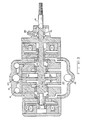
- valve actuator is illustrated sequentially in Figures 1-8 to illustrate various component locations and functions in moving a poppet valve or other component (not shown) from a closed to an open position. Motion in the opposite direction will be clearly understood from the symmetry of the components.
- a pneumatically powered valve actuator is shown having a valve actuator housing 19 and a piston 13 reciprocable within the housing along the axis of the shaft or stem 11, the piston 13 has a pair of oppositely facing primary working surfaces 38 and 40, a pressurized air source 39, a pair of air control valves 15 and 17 reciprocable along the axis relative to both the housing 19 and the piston 13 between open and closed positions.
- a magnetic attraction or magnetic repulsion arrangement for selectively opening one of the air control valves to supply pressurized air from the air source to one of said primary working surfaces causes the piston to move.
- a pneumatic arrangement including intermediate air pressure source 43 decelerates the piston near the extremities of its reciprocation.
- Coil springs 135 and 137 may optionally be included to bias each air control valve to continuously urge the respective air valve away from the piston and toward an open position.
- the actuator includes a shaft or stem 11 which may form a part of or connect to an internal combustion engine poppet valve.
- the actuator also includes a low mass reciprocable piston 13, and a pair of reciprocating or slidding control valve members 15 and 17 enclosed within a housing 19.
- the control valve members 15 and 17 are latched in a closed position by high pressure air from air source 39 operating on control valve faces 21 and 23 and may be dislodged from their respective latched positions by energization of coils 25 and 27.
- the control valve members or shuttle valves 15 and 17 cooperate with both the piston 13 and the housing 19 to achieve the various porting functions during operation.
- the housing 19 has a high pressure inlet port 39, a low pressure outlet port 41 and an intermediate pressure port 43.
- the low pressure may be about atmospheric pressure while the intermediate pressure is about 10 psi. above atmospheric pressure and the high pressure is in the order of 100 psi. gauge pressure.
- Figure 1 shows an initial state with piston 13 in the extreme leftward position and with the air control valve 15 latched closed.
- the annular abutment end surface 29 is inserted into an annular slot in the housing 19 and seals against an o-ring 31. This seals the pressure in cavity 33 and prevents the application of any moving force to the main piston 13.
- the main piston 13 is being urged to the left (latched) by the pressure in cavity or chamber 35 which is greater than the pressure in chamber or cavity 37.
- annular opening 45 is in its final open position after having rapidly released compressed air from cavity 37 at the end of a previous leftward piston stroke.
- control valve moves toward the left.
- the shuttle valve 15 has moved toward the left, for example, 0.05 in. while piston 13 has moved toward the right about one-half that distance.
- the air valve 15 has opened because of the attractive force of coil 25 which has temporarily overpowered the air pressure holding force on face 21.
- the communication between cavity 51 and the low pressure outlet port 41 has not been interrupted by movement of the valve 15. This communication is maintained at all times by way of a series of openings 54 in control valve 15.
- Figure 3 shows the opening of the air valve 15 to about 0.10 in. and movement of the piston 13 about 0.150 in. to the right.
- the annular surface 62 which is shown as a portion of a right circular cylinder may be undercut (concave) or tapered (a conical surface) to restrict air flow more near one or both extremes of the travel of plate 47 to enhance damping without restricting motion intermediate the ends if desired.
- the air valve 15 is still in its extreme leftward position.
- the air valve is designed to close at about the same time as the main piston arrives at its furthest right hand location. Also, in Figure 5, the piston is continuing to compress the air in cavity 35 slowing its motion.
- the damping of the piston motion near its right extremity is adjustable by controlling the intermediate pressure level at port 43 to effectively control the density of the air initially entrapped in chamber 35. If this intermediate pressure is too high, the piston will rebound due to the high pressure of the compressed air in chamber 35. If this pressure is too low, the piston will approach its end position too fast and may mechanically rebound due to metallic deflection or mechanical spring back. With the correct pressure, the piston will gently come to rest in its right hand position.
- a further final damping of piston motion may be provided during the last few thousandths of an inch of travel by a small hydraulic damper including a fluid medium filled cavity 73 and a small piston 75 fastened to and moving with the main piston 13.
- the small piston 75 enters a shallow annular restricted area 77 displacing the fluid therefrom and bringing the main piston to rest.
- Fluid such as oil, may be supplied to the damping cavity 73 by way of inlet 85.
- valve 15 is about midway along its return to its closed position. Final damping is almost complete as the pressure in chamber 35 is being relieved through the annular opening at 69 and through the opening 81 and channel 83 to the low pressure port 41 so that the pressure throughout chamber 35 is reduced to nearly atmospheric pressure.
- valves 15 and 17 include a number of apertures such as 54 and 81 in their respective web portions allowing free air flow between chambers such as 35 and 83.
- the piston 13 is reaching a very low velocity, the damping is almost complete and the final damping by the small fluid piston 75 is underway.
- the main piston 13 has reached its righthand extreme in Figure 8 and air valve 15 has closed.
- the supply of high pressure air from the source 39 to chamber 37 and the surface 38 of piston 13 has long since been interrupted by piston edge 105 passing housing edge 55 as best seen in Figure 3.
- the piston 13 is held or latched in the position shown by the intermediate pressure in chamber 37 from source 43 acting on piston face 38.
- the intermediate pressure port 43 has been omitted.
- Ports 41 and 113 are at the same (typically atmospheric) pressure.
- the pressure latching feature is replaced by permanent magnets such as 115 and 117 which hold the piston in one of the extreme positions and are designed with a narrow air gap so that their holding force falls off rapidly as the piston moves away from them.
- the advantage of the scheme of Figure 9 is that the difference between the pressure at the port 39 and port 113 is greater so that a greater expansion ratio and, hence, greater efficiency are achieved.
- the difference in pressure between ports 113 and 41, which is the piston latching pressure is reduced or zero, thus the magnetic latching is employed.
- Figure 10 illustrates two modifications, one of which is suggested by the discussion of Figure 9 and the other of which is suggested by a somewhat similar structure in copending PNEUMATIC ACTUATOR WITH PERMANENT MAGNET CONTROL VALVE LATCHING.
- an adjustable pressure regulator 119 for example, of the type in which the spring force on a spring loaded pressure relief valve may be varied, allows the pressure differential between ports 41 and 121 to be selected so that the best expansion ratio without need to resort to the magnetic latches of Figure 9 may be used.
- An adjustable needle valve 123 in effect controls the throttling in passageway 83 (see Figure 7) and therefore also differentially controls damping of piston motion.
- FIG. 12 A comparison with Figure 1 reveals, in Figure 12, a pair of coil springs 135 and 137 nested in oppositely facing annular slots in piston 13.
- Spring 135 is compressed urging the piston 13 and control valve 15 away from one another while spring 137 is unstressed in the position shown.
- the force of the spring 135 will reduce the force required to be exerted by solenoid 25 in opening the valve 15, but may increase the required pressure differential for latching the piston in the position shown.
- Figure 13 combines the concepts of Figure 12 with electromagnetic repulsion techniques of the type disclosed in the abovementioned copending application Serial No. 021,195 entitled ELECTROMAGNETIC VALVE ACTUATOR to open control valve 15.
- coil 139 is energized to induce a current in a nonmagnetic conductive plate 141 and the two currents cause opposing magnetic fields which repel the plate 141.
- this arrangement consumes greater energy, but is capable of much faster operation.
Landscapes
- Engineering & Computer Science (AREA)
- Mechanical Engineering (AREA)
- General Engineering & Computer Science (AREA)
- Physics & Mathematics (AREA)
- Fluid Mechanics (AREA)
- Magnetically Actuated Valves (AREA)
- Actuator (AREA)
- Fluid-Driven Valves (AREA)
Applications Claiming Priority (2)
| Application Number | Priority Date | Filing Date | Title |
|---|---|---|---|
| US07/209,273 US4873948A (en) | 1988-06-20 | 1988-06-20 | Pneumatic actuator with solenoid operated control valves |
| US209273 | 1998-12-11 |
Publications (1)
| Publication Number | Publication Date |
|---|---|
| EP0347977A1 true EP0347977A1 (de) | 1989-12-27 |
Family
ID=22778104
Family Applications (1)
| Application Number | Title | Priority Date | Filing Date |
|---|---|---|---|
| EP89201534A Ceased EP0347977A1 (de) | 1988-06-20 | 1989-06-14 | Pneumatisches Stellglied mit elektromagnetischen Steuerventilen |
Country Status (5)
| Country | Link |
|---|---|
| US (1) | US4873948A (de) |
| EP (1) | EP0347977A1 (de) |
| JP (1) | JPH0238780A (de) |
| KR (1) | KR900000602A (de) |
| CA (1) | CA1314775C (de) |
Cited By (1)
| Publication number | Priority date | Publication date | Assignee | Title |
|---|---|---|---|---|
| EP0443218A3 (en) * | 1989-12-26 | 1991-11-06 | Magnavox Government And Industrial Electronics Company | Electro-hydraulic valve actuator |
Families Citing this family (14)
| Publication number | Priority date | Publication date | Assignee | Title |
|---|---|---|---|---|
| US5003938A (en) * | 1989-12-26 | 1991-04-02 | Magnavox Government And Industrial Electronics Company | Pneumatically powered valve actuator |
| US5029516A (en) * | 1989-12-26 | 1991-07-09 | North American Philips Corporation | Pneumatically powered valve actuator |
| US5022359A (en) * | 1990-07-24 | 1991-06-11 | North American Philips Corporation | Actuator with energy recovery return |
| US5193495A (en) * | 1991-07-16 | 1993-03-16 | Southwest Research Institute | Internal combustion engine valve control device |
| US5339777A (en) * | 1993-08-16 | 1994-08-23 | Caterpillar Inc. | Electrohydraulic device for actuating a control element |
| US5647318A (en) * | 1994-07-29 | 1997-07-15 | Caterpillar Inc. | Engine compression braking apparatus and method |
| US5540201A (en) * | 1994-07-29 | 1996-07-30 | Caterpillar Inc. | Engine compression braking apparatus and method |
| US5526784A (en) * | 1994-08-04 | 1996-06-18 | Caterpillar Inc. | Simultaneous exhaust valve opening braking system |
| US6092545A (en) * | 1998-09-10 | 2000-07-25 | Hamilton Sundstrand Corporation | Magnetic actuated valve |
| JP4306519B2 (ja) * | 2003-09-29 | 2009-08-05 | アイシン・エィ・ダブリュ株式会社 | 圧力制御弁 |
| WO2011026173A1 (en) * | 2009-09-01 | 2011-03-10 | Biopower Systems Pty Ltd | Device for capturing energy from an oscillating drive member |
| US9498354B2 (en) | 2013-03-13 | 2016-11-22 | Milwaukee School Of Engineering | Actuation system for a joint |
| IT201800004121A1 (it) * | 2018-03-30 | 2019-09-30 | Miro Capitanio | Sistema valvolare antistallo bistabile |
| EP3597939B1 (de) * | 2018-07-20 | 2022-04-13 | Hamilton Sundstrand Corporation | Servoventil |
Citations (2)
| Publication number | Priority date | Publication date | Assignee | Title |
|---|---|---|---|---|
| DE421002C (de) * | 1925-11-04 | D Aviat Louis Breguet Sa Des A | Steuerung von Ventilen, insbesondere fuer Explosionsmotoren, durch Fluessigkeiten oder Gase | |
| US3844528A (en) * | 1971-12-30 | 1974-10-29 | P Massie | Electrically operated hydraulic valve particularly adapted for pollution-free electronically controlled internal combustion engine |
Family Cites Families (5)
| Publication number | Priority date | Publication date | Assignee | Title |
|---|---|---|---|---|
| DE197808C (de) * | ||||
| US2552960A (en) * | 1946-09-27 | 1951-05-15 | Nordberg Manufacturing Co | Gas actuated inlet valve |
| CH592835A5 (de) * | 1975-04-29 | 1977-11-15 | Lucifer Sa | |
| CH620748A5 (de) * | 1978-04-04 | 1980-12-15 | Lucifer Sa | |
| US4605197A (en) * | 1985-01-18 | 1986-08-12 | Fema Corporation | Proportional and latching pressure control device |
-
1988
- 1988-06-20 US US07/209,273 patent/US4873948A/en not_active Expired - Lifetime
-
1989
- 1989-06-14 EP EP89201534A patent/EP0347977A1/de not_active Ceased
- 1989-06-16 CA CA000603010A patent/CA1314775C/en not_active Expired - Fee Related
- 1989-06-17 KR KR1019890008363A patent/KR900000602A/ko not_active Withdrawn
- 1989-06-20 JP JP1155918A patent/JPH0238780A/ja active Pending
Patent Citations (2)
| Publication number | Priority date | Publication date | Assignee | Title |
|---|---|---|---|---|
| DE421002C (de) * | 1925-11-04 | D Aviat Louis Breguet Sa Des A | Steuerung von Ventilen, insbesondere fuer Explosionsmotoren, durch Fluessigkeiten oder Gase | |
| US3844528A (en) * | 1971-12-30 | 1974-10-29 | P Massie | Electrically operated hydraulic valve particularly adapted for pollution-free electronically controlled internal combustion engine |
Cited By (1)
| Publication number | Priority date | Publication date | Assignee | Title |
|---|---|---|---|---|
| EP0443218A3 (en) * | 1989-12-26 | 1991-11-06 | Magnavox Government And Industrial Electronics Company | Electro-hydraulic valve actuator |
Also Published As
| Publication number | Publication date |
|---|---|
| US4873948A (en) | 1989-10-17 |
| KR900000602A (ko) | 1990-01-30 |
| JPH0238780A (ja) | 1990-02-08 |
| CA1314775C (en) | 1993-03-23 |
Similar Documents
| Publication | Publication Date | Title |
|---|---|---|
| US4852528A (en) | Pneumatic actuator with permanent magnet control valve latching | |
| US4831973A (en) | Repulsion actuated potential energy driven valve mechanism | |
| US4883025A (en) | Potential-magnetic energy driven valve mechanism | |
| US4873948A (en) | Pneumatic actuator with solenoid operated control valves | |
| US4974495A (en) | Electro-hydraulic valve actuator | |
| EP0468571A1 (de) | Ventilstellglied mit hydraulischem Antrieb und pneumatischem Rücklauf | |
| EP0377244B1 (de) | Schnell arbeitendes Ventil | |
| US4915015A (en) | Pneumatic actuator | |
| US4899700A (en) | Pneumatically powered valve actuator | |
| US4942852A (en) | Electro-pneumatic actuator | |
| US4875441A (en) | Enhanced efficiency valve actuator | |
| US4991548A (en) | Compact valve actuator | |
| US5003938A (en) | Pneumatically powered valve actuator | |
| US4872425A (en) | Air powered valve actuator | |
| US5029516A (en) | Pneumatically powered valve actuator |
Legal Events
| Date | Code | Title | Description |
|---|---|---|---|
| PUAI | Public reference made under article 153(3) epc to a published international application that has entered the european phase |
Free format text: ORIGINAL CODE: 0009012 |
|
| AK | Designated contracting states |
Kind code of ref document: A1 Designated state(s): DE ES FR GB IT SE |
|
| 17P | Request for examination filed |
Effective date: 19900618 |
|
| 17Q | First examination report despatched |
Effective date: 19910919 |
|
| RAP1 | Party data changed (applicant data changed or rights of an application transferred) |
Owner name: MAGNAVOX ELECTRONIC SYSTEMS COMPANY |
|
| STAA | Information on the status of an ep patent application or granted ep patent |
Free format text: STATUS: THE APPLICATION HAS BEEN REFUSED |
|
| 18R | Application refused |
Effective date: 19940718 |