EP0347867A2 - Lighting system - Google Patents
Lighting system Download PDFInfo
- Publication number
- EP0347867A2 EP0347867A2 EP89111250A EP89111250A EP0347867A2 EP 0347867 A2 EP0347867 A2 EP 0347867A2 EP 89111250 A EP89111250 A EP 89111250A EP 89111250 A EP89111250 A EP 89111250A EP 0347867 A2 EP0347867 A2 EP 0347867A2
- Authority
- EP
- European Patent Office
- Prior art keywords
- lighting system
- vertical support
- reflector
- light source
- area
- Prior art date
- Legal status (The legal status is an assumption and is not a legal conclusion. Google has not performed a legal analysis and makes no representation as to the accuracy of the status listed.)
- Granted
Links
Images


Classifications
-
- F—MECHANICAL ENGINEERING; LIGHTING; HEATING; WEAPONS; BLASTING
- F21—LIGHTING
- F21V—FUNCTIONAL FEATURES OR DETAILS OF LIGHTING DEVICES OR SYSTEMS THEREOF; STRUCTURAL COMBINATIONS OF LIGHTING DEVICES WITH OTHER ARTICLES, NOT OTHERWISE PROVIDED FOR
- F21V7/00—Reflectors for light sources
- F21V7/0008—Reflectors for light sources providing for indirect lighting
- F21V7/0016—Reflectors for light sources providing for indirect lighting on lighting devices that also provide for direct lighting, e.g. by means of independent light sources, by splitting of the light beam, by switching between both lighting modes
-
- F—MECHANICAL ENGINEERING; LIGHTING; HEATING; WEAPONS; BLASTING
- F21—LIGHTING
- F21S—NON-PORTABLE LIGHTING DEVICES; SYSTEMS THEREOF; VEHICLE LIGHTING DEVICES SPECIALLY ADAPTED FOR VEHICLE EXTERIORS
- F21S2/00—Systems of lighting devices, not provided for in main groups F21S4/00 - F21S10/00 or F21S19/00, e.g. of modular construction
-
- F—MECHANICAL ENGINEERING; LIGHTING; HEATING; WEAPONS; BLASTING
- F21—LIGHTING
- F21S—NON-PORTABLE LIGHTING DEVICES; SYSTEMS THEREOF; VEHICLE LIGHTING DEVICES SPECIALLY ADAPTED FOR VEHICLE EXTERIORS
- F21S6/00—Lighting devices intended to be free-standing
- F21S6/002—Table lamps, e.g. for ambient lighting
- F21S6/003—Table lamps, e.g. for ambient lighting for task lighting, e.g. for reading or desk work, e.g. angle poise lamps
-
- F—MECHANICAL ENGINEERING; LIGHTING; HEATING; WEAPONS; BLASTING
- F21—LIGHTING
- F21V—FUNCTIONAL FEATURES OR DETAILS OF LIGHTING DEVICES OR SYSTEMS THEREOF; STRUCTURAL COMBINATIONS OF LIGHTING DEVICES WITH OTHER ARTICLES, NOT OTHERWISE PROVIDED FOR
- F21V14/00—Controlling the distribution of the light emitted by adjustment of elements
- F21V14/04—Controlling the distribution of the light emitted by adjustment of elements by movement of reflectors
-
- F—MECHANICAL ENGINEERING; LIGHTING; HEATING; WEAPONS; BLASTING
- F21—LIGHTING
- F21V—FUNCTIONAL FEATURES OR DETAILS OF LIGHTING DEVICES OR SYSTEMS THEREOF; STRUCTURAL COMBINATIONS OF LIGHTING DEVICES WITH OTHER ARTICLES, NOT OTHERWISE PROVIDED FOR
- F21V21/00—Supporting, suspending, or attaching arrangements for lighting devices; Hand grips
- F21V21/06—Bases for movable standing lamps; Fixing standards to the bases
-
- F—MECHANICAL ENGINEERING; LIGHTING; HEATING; WEAPONS; BLASTING
- F21—LIGHTING
- F21V—FUNCTIONAL FEATURES OR DETAILS OF LIGHTING DEVICES OR SYSTEMS THEREOF; STRUCTURAL COMBINATIONS OF LIGHTING DEVICES WITH OTHER ARTICLES, NOT OTHERWISE PROVIDED FOR
- F21V23/00—Arrangement of electric circuit elements in or on lighting devices
- F21V23/02—Arrangement of electric circuit elements in or on lighting devices the elements being transformers, impedances or power supply units, e.g. a transformer with a rectifier
-
- F—MECHANICAL ENGINEERING; LIGHTING; HEATING; WEAPONS; BLASTING
- F21—LIGHTING
- F21W—INDEXING SCHEME ASSOCIATED WITH SUBCLASSES F21K, F21L, F21S and F21V, RELATING TO USES OR APPLICATIONS OF LIGHTING DEVICES OR SYSTEMS
- F21W2131/00—Use or application of lighting devices or systems not provided for in codes F21W2102/00-F21W2121/00
- F21W2131/40—Lighting for industrial, commercial, recreational or military use
- F21W2131/402—Lighting for industrial, commercial, recreational or military use for working places
Definitions
- the invention relates to a lighting system, in particular for uniformly illuminating limited work surfaces, consisting of at least one light source and a reflector assigned to it.
- Known lighting systems usually do not allow individual adaptation of the lighting to the respective workplace, are often critical with regard to the glare required in computer workplaces and generally do not allow the position of the workplaces to be changed without impairing the lighting quality of the workplace concerned.
- the object of the invention is to provide a lighting system of the type specified in the preamble of claim 1 in such a way that an optimal, glare-free illumination of the respective workplace is achieved without the need for light planning that encompasses the entire entire space and thereby does not impair the usable area of the ar working area must be accepted.
- the lighting system should also be suitable for individualizing the individual workplace and its effectiveness should not be impaired even if changes have to be made in the respective position of the workplace.
- the reflector is designed as a large-area reflector that at least partially spans the respective work surface and is held on at least one vertical support, and that at least one light source that radiates against the large-area reflector is held on at least one vertical support in the area between the work surface and the large-area reflector is.
- the large-area reflector on the vertical support is designed to be adjustable with regard to the distance and / or the inclination to the work surface and, above all, its intrinsic curvature can also be changed is, so that in each case the desired uniformity of the work surface lighting and the desired brightness can be achieved, specifically for the respective workplace and independently of neighboring workplaces.
- the vertical support advantageously consists of individual sections which can be coupled and mutually fixed, these individual sections comprising support sections and supporting functional sections for light sources and ballasts can be combined as desired.
- the couplings between the individual sections are designed both as mechanically stable plug-in, latching or screw connections, and are preferably provided with electrical coupling units which inevitably ensure the necessary electrical connections when the mechanical coupling is carried out.
- the mechanical coupling can take place via conically interlocking elements, the electrical connection parts being arranged concentrically and the positive and non-positive connection between the two mechanical parts to be coupled being achieved via a screw sleeve.
- the electrical connection elements can be used in pin-sleeve form or in the form of concentric contact elements.
- a diagonal division can be provided in such a way that a mechanically stable triangular beam that absorbs all mechanical loads is combined with a likewise triangular receiving space for the electrical functional elements.
- the light source assigned to the large-area reflector is combined at the same time with at least one direct emitter, one direct light source or one light source delivering both direct light and indirect light via the large-area reflector.
- a separate additional light source which is also preferably held on the vertical support, can be used.
- the brightness is preferably selected so that direct light and reflected light have the same brightness on the work surface, thus ensuring the typical softness of the indirect light and the required absence of shadows on the entire work surface.
- Fig. 1 shows an example of a piece of work furniture a desk 1 with a work surface 2, which is illuminated by means of the individually adapted to this work surface 2 lighting system according to the invention in accordance with the respective requirements with indirect and direct light in an optimal way, since there are no disturbing structures and there is no shadow formation.
- the lighting system comprises a vertical support 3, which can be provided with a stable base, but is preferably coupled directly to the desk 1 via an interface connection unit, as well as a large area reflector 4 and one attached to the vertical support 3 Light source 5, which radiates against the large area reflector 4 at predeterminable angles.
- ballast 6 is required for the light source 5
- this ballast 6 is preferably designed as a separate unit, likewise held on the vertical support 3. This has the essential advantage that the ballast is not affected by the heat development of the light source, which is of particular importance for electronic ballasts and increases their long-term functionality.
- the large-area reflector 4 extends over a substantial part of the width of the working surface 2 and can be designed, for example, in the form of an acute-angled, curved sail, which is realized by means of a tensioning frame 10, which is covered with a suitable reflective material.
- the large area reflector 4 is preferably attached to the vertical column 3 by means of a lockable swivel or ball joint 7 and can be equipped with a suitable counterweight 8.
- the lockable joint 7 can be telescopically extendable for the height adjustment of the large-area reflector 4, but it is also possible to adjust the height by inserting an intermediate piece, since the vertical support 3 preferably consists of modular sections to be connected to one another, in particular to be screwed together, both of which only support function possessing individual sections are provided, as well as carrier sections in the form of functional units, such a functional unit comprising, for example, a light source or a ballast.
- the light source 5 can also be combined with a direct emitter 9, which is also optionally designed to be directional and enables additional small-area irradiation of the work surface with the brightness of the indirect light of corresponding brightness.
- a direct emitter 9 which is also optionally designed to be directional and enables additional small-area irradiation of the work surface with the brightness of the indirect light of corresponding brightness.
- Fig. 2 shows in a highly schematic manner a possible embodiment of a connection or interface unit 11, as it can be integrated in the manner of a standard unit in work furniture in the edge or corner area, so that a lighting system according to the invention can then be connected without difficulty and the required stability of the lighting system is ensured by the coupling with the work furniture.
- the interface unit 11 is shown in FIG. 2 in the left part in a first embodiment provided with a flange 18 and in the right part in a second flange-free embodiment for a pipe coupling.
- the tubular vertical support 3 is screwed to a coupling sleeve 12, and this coupling sleeve 12 has a conically tapering end which engages in a sleeve 20 which is complementary and is provided with either a flange 18 or an external screw thread and with respect to this sleeve 20 can be fixed by means of a clamping screw member 14.
- This clamping member 14 engages over an annular shoulder of the coupling sleeve 12 and in this way allows an extremely stable clamping fixation to be achieved by a simple screwing operation.
- the advantage of this construction is that the outer diameter of all visible cylindrical parts is the same, so that in the assembled state there is a harmonious connection of the respective vertical support 3 to the connection unit 11.
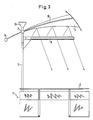
- the embodiment variant according to FIG. 3 differs from the embodiment according to FIG. 1 essentially in that the large-area reflector 4 is assigned a light source 5 in the form of a tube lamp, which extends over a substantial part of the width of the working surface 2 and possibly downwards can be shielded from the working surface 2 by a preferably adjustable screen.
- a light source 5 in the form of a tube lamp, which extends over a substantial part of the width of the working surface 2 and possibly downwards can be shielded from the working surface 2 by a preferably adjustable screen.
- an additional light source 16 for example in the form of a spotlight, can also be attached to the vertical support above the large area reflector 4 in order to obtain a defined room illumination independently of the individual workplace lighting guaranteed by the lighting system according to the invention.
- FIG. 4 shows a further embodiment of the invention, in which the light source 5 assigned to the large-area reflector 4 is spaced apart from the vertical support 3 and is designed such that a direct light source 17 can be effective approximately in the region of the center of the work surface 2.
- the direct light source 17 is preferably identical in terms of the light means used to the light source used to generate the indirect light, in which case a transparent area is provided on the work surface side, which is selected so that there is at least essentially on the work surface for the direct and indirect light gives the same brightness.
- a direct light source 15 which is preferably designed to be horizontal and / or pivotable in a vertical plane, can optionally or alternatively be integrated in the structure of the vertical support 3 consisting of individual sections can be used optionally without affecting the usable work surface 2.
Landscapes
- Engineering & Computer Science (AREA)
- General Engineering & Computer Science (AREA)
- Non-Portable Lighting Devices Or Systems Thereof (AREA)
- Fastening Of Light Sources Or Lamp Holders (AREA)
- Preparation Of Compounds By Using Micro-Organisms (AREA)
- Circuit Arrangement For Electric Light Sources In General (AREA)
- Lasers (AREA)
Abstract
Description
Die Erfindung betrifft ein Beleuchtungssystem, insbesondere zur gleichmäßigen Ausleuchtung begrenzter Arbeitsflächen, bestehend aus zumindest einer Lichtquelle und einem dieser zugeordneten Reflektor.The invention relates to a lighting system, in particular for uniformly illuminating limited work surfaces, consisting of at least one light source and a reflector assigned to it.
Die Beleuchtung von Arbeitsflächen, insbesondere die Beleuchtung individueller Arbeitsflächer in Form von Schreibtischen, Computerarbeitsplätzen und dergleichen, stellt an die jeweilige Lichtplanung erhebliche Anforderungen, die aufgrund baulicher Gegebenheiten, unzureichender elektrischer Grundinstallation sowie der häufig geforderten Variationsmöglichkeit hinsichtlich der Arbeitsplatzanordnungen nur schwer und häufig nicht optimal zu erfüllen sind.The lighting of work surfaces, in particular the lighting of individual work surfaces in the form of desks, computer workstations and the like, places considerable demands on the respective lighting design, which is difficult and often not optimal due to the structural conditions, inadequate basic electrical installation and the frequently required variation with regard to the work station arrangements are fulfilled.
Bekannte Lichtsysteme gestatten üblicherweise keine individuelle Anpassung der Beleuchtung an den jeweiligen Arbeitsplatz, sind häufig hinsichtlich der bei Computerarbeitsplätzen geforderten Blendfreiheit kritisch und lassen im Regelfall keine Veränderung der Position der Arbeitsplätze ohne Beeinträchtigung der Beleuchtungsqualität des betreffenden Arbeitsplatzes zu.Known lighting systems usually do not allow individual adaptation of the lighting to the respective workplace, are often critical with regard to the glare required in computer workplaces and generally do not allow the position of the workplaces to be changed without impairing the lighting quality of the workplace concerned.
Individuelle Arbeitsplatzbeleuchtungen beeinträchtigen nicht nur die nutzbare Größe der jeweils zur Verfügung stehenden Arebitsfläche, sondern erbringen im Regelfall auch keine gleichmäßige Ausleuchtung der gesamten Arbeitsfläche. Häufig kommt es bei solchen Systemen auch zu Blendeffekten in Bildschirmen, was sehr unerwünscht ist.Individual workplace lighting not only affects the usable size of the available arebit area, but generally does not provide even illumination of the entire work area. Such systems often also cause glare on screens, which is very undesirable.
Aufgabe der Erfindung ist es, ein Beleuchtungssystem der im Oberbegriff des Anspruchs 1 angegebenen Art in der Weise auszubilden, daß ohne das Erfordernis einer den jeweiligen Gesamtraum umfassenden Lichtplanung eine optimale, blendfreie Ausleuchtung des jeweiligen Arbeitsplatzes erzielt wird und dabei keine Beeinträchtigung des nutzbaren Bereichs der Ar beitsfläche in Kauf genommen werden muß. Das Beleuchtungssystem soll außerdem zur Individualisierung des einzelnen Arbeitsplatzes geeignet sein und in seiner Wirksamkeit auch dann nicht beeinträchtigt werden, wenn Änderungen in der jeweiligen Position der Arbeitsplätze vorgenommen werden müssen.The object of the invention is to provide a lighting system of the type specified in the preamble of claim 1 in such a way that an optimal, glare-free illumination of the respective workplace is achieved without the need for light planning that encompasses the entire entire space and thereby does not impair the usable area of the ar working area must be accepted. The lighting system should also be suitable for individualizing the individual workplace and its effectiveness should not be impaired even if changes have to be made in the respective position of the workplace.
Gelöst wird diese Aufgabe nach der Erfindung im wesentlichen dadurch, daß der Reflektor als die jeweilige Arbeitsfläche zumindest teilweise überspannender, an wenigstens einem Vertikalträger gehalterter Großflächenreflektor ausgebildet ist und daß an zumindest einem Vertikalträger im Bereich zwischen Arbeitsfläche und Großflächenreflektor wenigstens eine gegen den Großflächenreflektor strahlende Lichtquelle gehaltert ist.This object is essentially achieved according to the invention in that the reflector is designed as a large-area reflector that at least partially spans the respective work surface and is held on at least one vertical support, and that at least one light source that radiates against the large-area reflector is held on at least one vertical support in the area between the work surface and the large-area reflector is.
Durch die Verwendung eines arbeitsflächenbezogenen Großflächenreflektors wird es möglich, unabhängig von dem jeweiligen Raum und insbesondere unabhängig von der Raumhöhe eine optimale und gleichmäßige, insbesondere indirekte Ausleuchtung der jeweiligen Arbeitsfläche zu erreichen, und zwar unter gleichzeitiger Minimierung der dazu erforderlichen Energie und unter Vermeidung jeglicher Blendeffekte.By using a work surface-related large area reflector, it is possible to achieve optimal and uniform, in particular indirect, illumination of the respective work surface, regardless of the respective room and in particular regardless of the room height, while minimizing the energy required and avoiding any glare effects.
Aufgrund der Anordnung und Ausgestaltung dieses Großflächenreflektors und der Ausnutzung des Vertikalträgers zur Halterung des Großflächenreflektors und zur Halterung der diesem zugeordneten Lichtquelle ist es möglich, den Anstrahlwinkel so zu wählen, daß einerseits keinerlei Blendeffekte auftreten und andererseits eine bestmögliche Lichtausbeute über die Reflexion erzielt wird, wobei die Arbeitsfläche selbst in ihrer nutzbaren Größe durch das Beleuchtungssystem in keiner Weise beeinträchtigt wird.Due to the arrangement and design of this large-area reflector and the use of the vertical support for holding the large-area reflector and for holding the light source assigned to it, it is possible to choose the angle of incidence so that on the one hand no glare effects occur and on the other hand the best possible light yield is achieved by reflection, whereby the work surface itself is not affected in any way by the lighting system in its usable size
Aufgrund der arbeitsplatzbezogenen Vollflächenbeleuchtung entfällt auch eine sonst für den jeweiligen Raum erforderliche Lichtplanung, und es ergeben sich keinerlei Schwierigkeiten in Falle einer Umstellung der Arbeitsmöbel, da das Beleuchtungssystem automatisch mitwandert und an einem neuen Platz in seiner Funktion in keiner Weise beeinträchtigt ist.Due to the workplace-related full-surface lighting, there is also no need for lighting planning otherwise required for the respective room, and there are no difficulties in the event of a change of work furniture, since the lighting system automatically moves along and its function is not impaired in any way at a new place.
Den individuellen Gegebenheiten und Wünschen hinsichtlich der Arbeitsplatzbeleuchtung kann bei einem Beleuchtungssystem nach der Erfindung bestmöglich Rechnung getragen werden, da gemäß einer vorteilhaften Auführungsvariante der Großflächenreflektor am Vertikalträger bezüglich des Abstandes und/oder der Neigung zur Arbeitsfläche verstellbar ausgebildet ist und vor allem auch in seiner Eigenwölbung veränderbar ist, so daß in jedem Falle die gewünschte Gleichmäßigkeit der Arbeitsflächenbeleuchtung und auch die gewünschte Helligkeit erzielt werden kann, und zwar individuell für den jeweiligen Arbeitsplatz und unabhängig von benachbarten Arbeitsplätzen.The individual conditions and wishes with regard to workplace lighting can be taken into account in the best possible way in a lighting system according to the invention, since, according to an advantageous embodiment variant, the large-area reflector on the vertical support is designed to be adjustable with regard to the distance and / or the inclination to the work surface and, above all, its intrinsic curvature can also be changed is, so that in each case the desired uniformity of the work surface lighting and the desired brightness can be achieved, specifically for the respective workplace and independently of neighboring workplaces.
Vorteilhafterweise besteht der Vertikalträger aus miteinander kuppel- und gegenseitig fixierbaren Einzelabschnitten, wobei diese Einzelabschnitte aus Trägerabschnitten und tragenden Funktionsabschnitten für Lichtquellen und Vorschaltgeräte beliebig kombinierbar sind. Die Kupplungen zwischen den Einzelabschnitten sind sowohl als mechanisch stabile Steck-, Rast- oder Schraubverbindungen ausgebildet, und sind vorzugsweise mit elektrischen Kuppeleinheiten versehen, die bei Vornahme der mechanischen Kopplung die notwendigen elektrischen Verbindungen zwangsläufig gewährleisten.The vertical support advantageously consists of individual sections which can be coupled and mutually fixed, these individual sections comprising support sections and supporting functional sections for light sources and ballasts can be combined as desired. The couplings between the individual sections are designed both as mechanically stable plug-in, latching or screw connections, and are preferably provided with electrical coupling units which inevitably ensure the necessary electrical connections when the mechanical coupling is carried out.
Besonders vorteilhaft ist es, in einem Eck- oder Randbereich des jeweiligen Arbeitsmöbels, insbesondere Arbeitstisches, eine mechanisch/elektrische Schnittstelle vorzusehen, mit der der Vertikalträger gekuppelt werden kann. Dabei ist si cherzustellen, daß einerseits die notwendige mechanische Festigkeit erzielt und andererseits unter Beachtung der bestehenden Sicherheitsvorschriften eine einwandfreie elektrische Kontaktgabe gewährleistet ist. Beispielsweise kann die mechanische Kopplung über konisch ineinandergreifende Elemente erfolgen, wobei die elektrischen Verbindungsteile konzentrisch angeordnet sind und die form- und kraftschlüssige Verbindung zwischen den beiden zu koppelnden mechanischen Teilen über eine Schraubhülse erzielt wird. Die elektrischen Anschlußelemente können dabei in Stift-Hülsenform oder auch in Form konzentrischer Kontaktelemente Verwendung finden.It is particularly advantageous to provide a mechanical / electrical interface with which the vertical support can be coupled in a corner or edge area of the respective work furniture, in particular a work table. Here is si Ensure that on the one hand the necessary mechanical strength is achieved and on the other hand that proper electrical contact is ensured while observing the existing safety regulations. For example, the mechanical coupling can take place via conically interlocking elements, the electrical connection parts being arranged concentrically and the positive and non-positive connection between the two mechanical parts to be coupled being achieved via a screw sleeve. The electrical connection elements can be used in pin-sleeve form or in the form of concentric contact elements.
Im Falle der Verwendung von im Querschnitt rechteckigen Vertikalträgern und entsprechend ausgebildeter Schnittstellen kann eine Diagonalunterteilung in der Weise vorgesehen werden, daß dann ein mechanisch stabiler und alle mechanischen Belastungen aufnehmender Dreieckträger mit einem ebenfalls dreieckigen Aufnahmeraum für die elektrischen Funktionselemente kombiniert wird.In the case of the use of vertical beams with a rectangular cross-section and correspondingly designed interfaces, a diagonal division can be provided in such a way that a mechanically stable triangular beam that absorbs all mechanical loads is combined with a likewise triangular receiving space for the electrical functional elements.
Nach einer weiteren Ausgestaltung der Erfindung ist vorgesehen, daß die dem Großflächenreflektor zugeordnete Lichtquelle gleichzeitig mit wenigstens einem Direktstrahler, einer Direktlichtquelle oder einer sowohl Direktlicht als auch indirektes Licht über den Großflächenreflektor liefernden Lichtquelle kombiniert ist. Gegebenenfalls kann zusätzlich zu dieser Lichtquelle eine getrennte weitere, ebenfalls am Vertikalträger vorzugsweise gehalterte Zusatzlichtquelle verwendet werden. In allen Fällen wird dabei vorzugsweise die Helligkeit so gewählt, daß direktes Licht und reflektiertes Licht gleiche Helligkeit auf der Arbeitsfläche besitzen und somit die typische Weichheit des indirekten Lichts sowie die geforderte Schattenfreiheit auf der gesamten Arbeitsfläche gewährleistet ist.According to a further embodiment of the invention, it is provided that the light source assigned to the large-area reflector is combined at the same time with at least one direct emitter, one direct light source or one light source delivering both direct light and indirect light via the large-area reflector. If necessary, in addition to this light source, a separate additional light source, which is also preferably held on the vertical support, can be used. In all cases, the brightness is preferably selected so that direct light and reflected light have the same brightness on the work surface, thus ensuring the typical softness of the indirect light and the required absence of shadows on the entire work surface.
Weitere besonders vorteilhafte Ausführungsformen der Erfindung sind in den Unteransprüchen angegeben.Further particularly advantageous embodiments of the invention are specified in the subclaims.
Die Erfindung wird nachfolgend unter Bezugnahme auf die Zeichnung anhand von Auführungsbeispielen näher erläutert; in der Zeichnung zeigt:
- Fig. 1 eine schematische Darstellung einer ersten Ausführungsform eines Beleuchtungssystems nach der Erfindung,
- Fig. 2 eine schematische Darstellung einer Schnittstellen-Anschlußeinheit zur Integration in ein Arbeitsmöbel,
- Fig. 3 eine Ausführungsvariante des Beleuchtungssystems nach Fig. 1, und
- Fig. 4 eine weitere Ausführungsform mit kombinierter direkter und indirekter Beleuchtung einer Arbeitsfläche.
- 1 is a schematic representation of a first embodiment of a lighting system according to the invention,
- 2 shows a schematic representation of an interface connection unit for integration into work furniture,
- 3 shows an embodiment variant of the lighting system according to FIG. 1, and
- Fig. 4 shows another embodiment with combined direct and indirect lighting of a work surface.
Fig. 1 zeigt als Beispiel für ein Arbeitsmöbel einen Schreibtisch 1 mit einer Arbeitsfläche 2, die mittels des individuell dieser Arbeitsfläche 2 angepaßten Beleuchtungssystems nach der Erfindung entsprechend den jeweiligen Anforderungen mit indirektem und direktem Licht in optimaler Weise ausgeleuchtet wird, da keine störenden Strukturen vorhanden sind und keine Schattenbildung auftritt.Fig. 1 shows an example of a piece of work furniture a desk 1 with a
Das Beleuchtungssystem umfaßt dabei einen Vertikalträger 3, welcher mit einem stabilen Standfuß versehen sein kann, jedoch vorzugsweise über eine Schnittstellen-Anschlußeinheit direkt mit dem Schreibtisch 1 gekoppelt ist, sowie einen am Vertikalträger 3 befestigten Großflächenreflektor 4 und eine Lichtquelle 5, die unter vorgebbaren Winkeln gegen den Großflächenreflektor 4 strahlt.The lighting system comprises a
Ist für die Lichtquelle 5 ein Vorschaltgerät 6 erforderlich, so wird dieses Vorschaltgerät 6 vorzugsweise als separate, ebenfalls am Vertikalträger 3 gehalterte Einheit ausgebildet. Dies hat den wesentlichen Vorteil, daß das Vorschaltgerät nicht durch die Wärmeentwicklung der Lichtquelle beeinträchtigt wird, was für elektronische Vorschaltgeräte von besonderer Bedeutung ist und deren Dauerfunktionstüchtigkeit erhöht.If a ballast 6 is required for the
Der Großflächenreflektor 4 erstreckt sich über einen wesentlichen Teil der Breite der Arbeitsfläche 2 und kann beispielsweise in Form eines spitzwinkligen, gekrümmten Segels ausgebildet sein, das mittels eines Spannrahmens 10 realisiert ist, welcher mit einem geeigneten reflektierenden Material bezogen ist.The large-area reflector 4 extends over a substantial part of the width of the
Der Großflächenreflektor 4 ist an der Vertikalsäule 3 vorzugsweise über ein feststellbares Schwenk- oder Kugelgelenk 7 befestigt und kann mit einem geeigneten Gegengewicht 8 ausgestattet sein.The large area reflector 4 is preferably attached to the
Das feststellbare Gelenk 7 kann zur Höhenverstellung des Großflächenreflektors 4 teleskopartig ausfahrbar angebracht sein, aber es ist auch möglich, eine Höhenverstellung durch Einfügen eines Zwischenstücks vorzunehmen, da der Vertikalträger 3 vorzugsweise aus baukastenartig miteinander zu verbindenden, insbesondere zu verschraubenden Einzelabschnitten besteht, wobei sowohl nur Trägerfunktion besitzende Einzelabschnitte vorgesehen sind, als auch Trägerabschnitte in Form von Funktionseinheiten, wobei eine solche Funktionseinheit beispielsweise eine Lichtquelle oder ein Vorschaltgerät umfaßt.The
Gegebenenfalls kann die Lichtquelle 5 auch noch mit einem Direktstrahler 9 kombiniert sein, der ggf. auch richtbar ausgebildet ist und eine zusätzliche Kleinflächenbestrahlung der Arbeitsfläche mit der Helligkeit des indirekten Lichts entsprechender Helligkeit ermöglicht.Optionally, the
Fig. 2 zeigt in stark schematisierter Weise eine mögliche Ausführungsform einer Anschluß- bzw. Schnittstelleneinheit 11, wie sie nach Art einer Standardeinheit in ein Arbeitsmöbel im Rand- oder Eckbereich integriert werden kann, so daß dann ohne Schwierigkeiten ein Beleuchtungssystem nach der Erfindung angeschlossen werden kann und die erforderliche Stabilität des Beleuchtungssystems durch die Kopplung mit dem Arbeitsmöbel gewährleistet ist.Fig. 2 shows in a highly schematic manner a possible embodiment of a connection or interface unit 11, as it can be integrated in the manner of a standard unit in work furniture in the edge or corner area, so that a lighting system according to the invention can then be connected without difficulty and the required stability of the lighting system is ensured by the coupling with the work furniture.
Die Schnittstelleneinheit 11 ist in Fig. 2 im linken Teil in einer ersten, mit einem Flansch 18 versehenen Ausführungsform und im rechten Teil in einer zweiten, flanschfreien Ausführungsform für eine Rohrkopplung gezeigt.The interface unit 11 is shown in FIG. 2 in the left part in a first embodiment provided with a
In beiden Ausführungsvarianten wird der rohrförmige Vertikalträger 3 mit einer Kuppelhülse 12 verschraubt, und diese Kuppelhülse 12 besitzt ein sich konisch verjüngendes Ende, das in eine komplementär ausgebildete, entweder mit einem Flansch 18 oder einem Außen- Schraubgewinde versehene Hülse 20 eingreift und bezüglich dieser Hülse 20 mittels eines Spann-Schrauborgans 14 fixierbar ist. Dieses Spannorgan 14 übergreift einen Ringansatz der Kuppelhülse 12 und gestattet es auf diese Weise, durch einen einfachen Schraubvorgang eine äußerst stabile Klemmfixierung zu erzielen. Von Vorteil ist bei dieser Konstruktion, daß der Außendurchmesser aller sichtbaren zylindrischen Teile gleich ist, so daß sich im montierten Zustand ein harmonischer Anschluß des jeweiligen Vertikalträgers 3 an der Anschlußeinheit 11 ergibt.In both variants, the tubular
Die Ausführungsvariante nach Fig. 3 unterscheidet sich von der Ausführungsform nach Fig. 1 im wesentlichen dadurch, daß dem Großflächenreflektor 4 eine Lichtquelle 5 in Form einer Röhrenleuchte zugeordnet ist, die sich über einen wesentlichen Teil der Breite der Arbeitsfläche 2 erstreckt und ggf. nach unten zur Arbeitsfläche 2 hin durch eine vorzugsweise verstellbare Blende abgeschirmt sein kann.The embodiment variant according to FIG. 3 differs from the embodiment according to FIG. 1 essentially in that the large-area reflector 4 is assigned a
Außerdem ist in Fig. 3 gezeigt, daß an dem Vertikalträger auch oberhalb des Großflächenreflektors 4 noch eine Zusatzlichtquelle 16, beispielsweise in Form eines Strahlers angebracht werden kann, um unabhängig von der durch das erfindungsgemäße Beleuchtungssystem gewährleisteten individuellen Arbeitsplatzbeleuchtung eine definierte Raumausleuchtung zu erhalten.In addition, it is shown in FIG. 3 that an
Fig. 4 zeigt eine weitere Ausführungsform der Erfindung, bei der die dem Großflächenreflektor 4 zugeordnete Lichtquelle 5 bezüglich des Vertikalträgers 3 beabstandet und so ausgebildet ist, daß etwa im Bereich der Mitte der Arbeitsfläche 2 eine Direktlichtquelle 17 wirksam werden kann.FIG. 4 shows a further embodiment of the invention, in which the
Die Direktlichtquelle 17 ist vorzugsweise hinsichtlich der verwendeten Lichtmittel identisch mit der zur Erzeugung des indirekten Lichtes verwendeten Lichtquelle, wobei in diesem Falle arbeitsflächenseitig ein Transparentbereich vorgesehen ist, der so gewählt wird, daß sich auf der Arbeitsfläche für das direkte und das indirekte Licht zumindest im wesentlichen gleiche Helligkeit ergibt.The
Außerdem ist in dieser Darstellung gezeigt, daß in dem aus Einzelabschnitten bestehenden Aufbau des Vertikalträgers 3 ggf. alternativ oder zusätzlich eine Direktlichtquelle 15 integriert werden kann, die vorzugweise horizontal und/oder in einer Vertikalebene verschwenkbar ausgebildet ist und somit ohne Beeinträchtigung der nutzbaren Arbeitsfläche 2 wahlweise zum Einsatz gebracht werden kann.In addition, it is shown in this illustration that a direct light source 15, which is preferably designed to be horizontal and / or pivotable in a vertical plane, can optionally or alternatively be integrated in the structure of the
Claims (20)
dadurch gekennzeichnet,
daß der Reflektor als die jeweilige Arbeitsfläche (2) zumindest teilweise überspannender, an wenigstens einem Vertikalträger (3) gehalterter Großflächenreflektor (4) ausgebildet ist und daß an zumindest einem Vertikalträger (3) im Bereich zwischen Arbeitsfläche (2) und Großflächenreflektor (4) wenigstens eine gegen den Großflächenreflektor (4) strahlende Lichtquelle (5) gehaltert ist.1. lighting system, in particular for uniform illumination of limited work surfaces, consisting of at least one light source and a reflector assigned to it,
characterized by
that the reflector is designed as a large-area reflector (4) which at least partially spans the respective work surface (2) and is supported on at least one vertical support (3) and that at least one vertical support (3) in the area between the work surface (2) and large-area reflector (4) is at least a light source (5) radiating against the large area reflector (4) is held.
dadurch gekennzeichnet,
daß der Großflächenreflektor (4) am Vertikalträger (3) bezüglich des Abstands und/oder der Neigung zur Arbeitsfläche (2) verstellbar ist.2. Lighting system according to claim 1,
characterized by
that the large area reflector (4) on the vertical support (3) is adjustable with respect to the distance and / or the inclination to the work surface (2).
dadurch gekennzeichnet,
daß der Großflächenreflektor (4) in seiner Eigenwölbung verstellbar ist.3. Lighting system according to claim 1 or 2,
characterized by
that the large area reflector (4) is adjustable in its own curvature.
dadurch gekennzeichnet,
daß der Großflächenreflektor (4) aus einem mit reflektierendem Material bespannten Rahmen (10) besteht.4. Lighting system according to one of the preceding claims,
characterized by
that the large area reflector (4) consists of a frame (10) covered with reflective material.
dadurch gekennzeichnet,
daß der Großflächenreflektor (4) nach Art eines Dreiecksegels ausgebildet und im Bereich seines spitz zulaufenden Endes mittels eines Fixiergelenks (7) am Vertikalträger (3) befestigt ist.5. Lighting system according to one of the preceding claims,
characterized by
that the large-area reflector (4) is designed in the manner of a triangular sail and is fastened to the vertical support (3) in the region of its tapering end by means of a fixing joint (7).
dadurch gekennzeichnet,
daß das Fixiergelenk (7) nach Art eines feststellbaren Schwenk- oder Kugelgelenks ausgebildet ist.6. Lighting system according to claim 5,
characterized by
that the fixing joint (7) is designed in the manner of a lockable swivel or ball joint.
dadurch gekennzeichnet,
daß der Großflächenreflektor (4) mit einem bezüglich des Fixiergelenks (7) vorzugsweise verstellbaren Gegengewicht (8) versehen ist.7. Lighting system according to one of the preceding claims,
characterized by
that the large area reflector (4) with a with respect to Fixing joint (7) preferably adjustable counterweight (8) is provided.
dadurch gekennzeichnet,
daß die Lichtquelle (5) höhenverstellbar und/oder schwenkbar am Vertikalträger (3) gehaltert und fixierbar ist.8. Lighting system according to one of the preceding claims,
characterized by
that the light source (5) is height-adjustable and / or pivotable on the vertical support (3) and can be fixed.
dadurch gekennzeichnet,
daß ein für die jeweilige Lichtquelle (5) erforderliches Vorschaltgerät (6) als separate, ebenfalls am Vertikalträger (3) gehalterte Einheit ausgebildet ist.9. Lighting system according to one of the preceding claims,
characterized by
that a ballast (6) required for the respective light source (5) is designed as a separate unit which is also held on the vertical support (3).
dadurch gekennzeichnet,
daß der Vertikalträger (3) aus miteinander kuppel- und gegenseitig fixierbaren Einzelabschnitten besteht und als Einzelabschnitte wahlweise Trägerabschnitte und tragende Funktionsabschnitte für Lichtquellen (5) und Vorschaltgeräte (6) kombinierbar sind.10. Lighting system according to one or more of the preceding claims,
characterized by
that the vertical support (3) consists of individual sections that can be coupled and mutually fixed and that individual sections can optionally be combined with support sections and supporting functional sections for light sources (5) and ballasts (6).
dadurch gekennzeichnet,
daß der Vertikalträger (3) zumindest mechanisch mit einer in einem Arbeitsflächenrandbereich oder Arbeitsflächeneckbereich vorgesehenen Anschlußeinheit (11) kuppelbar ist.11. Lighting system according to one or more of the preceding claims,
characterized by
that the vertical support (3) can be coupled at least mechanically to a connection unit (11) provided in a work area edge area or work area corner area.
dadurch gekennzeichnet,
daß die Anschlußeinheit (11) als mechanisch/elektrische Schnittstelle ausgebildet ist.12. Lighting system according to claim 11,
characterized by
that the connection unit (11) is designed as a mechanical / electrical interface.
dadurch gekennzeichnet,
daß am Vertikalträger (3) im Bereich zwischen der Arbeitsfläche (2) und der dem Großflächenreflektor (4) zugeordneten Lichtquelle (5) eine insbesondere horizontal und/oder vertikal schwenkbar ausgebildete Direktlichtquelle (15) gehaltert ist.13. Lighting system according to one of the preceding claims,
characterized by
that a direct light source (15) which is in particular horizontally and / or vertically pivotable is mounted on the vertical support (3) in the area between the work surface (2) and the light source (5) associated with the large area reflector (4).
dadurch gekennzeichnet,
daß die dem Großflächenreflektor (4) zugeordnete Lichtquelle (5) gleichzeitig wenigstens einen Direktstrahler (9) oder eine Direktlichtquelle (17) aufweist.14. Lighting system according to one of claims 1 to 12,
characterized by
that the light source (5) assigned to the large area reflector (4) has at least one direct emitter (9) or one direct light source (17) at the same time.
dadurch gekennzeichnet,
daß die Großflächenreflektor (4) zugeordnete Lichtquellet in ihrem Abstand zum Vertikalträger (3) durch Versetzen und/oder Verschwenken einstellbar ist.15. Lighting system according to one or more of the preceding claims,
characterized by
that the large-area reflector (4) associated light source can be adjusted in its distance from the vertical support (3) by moving and / or pivoting.
dadurch gekennzeichnet,
daß die dem Großflächenreflektor (4) zugeordnete Lichtquelle (5) röhrenförmig ausgebildet ist und sich ausgehend vom Bereich des seitlich der Arbeitsfläche (2) angeordneten Vertikalträgers (3) über zumindest die Hälfte der Arbeitsflächenbreite erstreckt.16. Lighting system according to one of the preceding claims,
characterized by
that the light source (5) assigned to the large area reflector (4) is tubular and extends from the area of the vertical support (3) arranged to the side of the working area (2) over at least half of the working area width.
dadurch gekennzeichnet,
daß der Großflächenreflektor (4) sich zumindest im wesentlichen über etwa 2/3 der Breite der Arbeitsfläche (2) erstreckt.17. Lighting system according to one of the preceding claims,
characterized by
that the large area reflector (4) extends at least substantially over about 2/3 of the width of the working surface (2).
dadurch gekennzeichnet,
daß die Helligkeit des über den Großflächenreflektor (4) auf die Arbeitsfläche (2) gerichteten indirekten Lichtes zumindest im wesentlichen gleich der Helligkeit des von einer Direktlichtquelle kommenden Lichtes ist.18. Lighting system according to one or more of the preceding claims,
characterized by
that the brightness of the indirect light directed via the large area reflector (4) onto the work surface (2) is at least substantially equal to the brightness of the light coming from a direct light source.
dadurch gekennzeichnet,
daß die Anschlußeinheit (11) für den Schnittstelleneinbau mit einer einen Flansch (18) aufweisenden Hülse versehen ist, die eine konische Aufnahme für eine Koppelhülse (12) besitzt, die mittels eines Schraub-Spannorgans fixierbar ist und an ihrem freien Ende ein Außengewinde aufweist, das mit dem Vertikalträger (3) verschraubbar ist.19. Lighting system according to one of the preceding claims,
characterized by
that the connection unit (11) for the interface installation is provided with a sleeve (18) with a flange, which has a conical receptacle for a coupling sleeve (12), which can be fixed by means of a screw tensioning element and has an external thread at its free end, which can be screwed to the vertical support (3).
dadurch gekennzeichnet,
daß für eine Ankopplung des Vertikalträgers (3) an eine Rohraufnahme die Hülse anstelle eines Anschlußflanches ein Außengewinde zur Verschraubung mit der entsprechenden Rohraufnahme besitzt.20. Lighting system according to claim 19,
characterized by
that for coupling the vertical support (3) to a pipe receptacle, the sleeve has an external thread for screwing to the corresponding pipe receptacle instead of a connecting flange.
Applications Claiming Priority (2)
| Application Number | Priority Date | Filing Date | Title |
|---|---|---|---|
| DE3820926 | 1988-06-21 | ||
| DE3820926A DE3820926A1 (en) | 1988-06-21 | 1988-06-21 | LIGHTING SYSTEM |
Publications (3)
| Publication Number | Publication Date |
|---|---|
| EP0347867A2 true EP0347867A2 (en) | 1989-12-27 |
| EP0347867A3 EP0347867A3 (en) | 1990-06-13 |
| EP0347867B1 EP0347867B1 (en) | 1994-10-12 |
Family
ID=6356921
Family Applications (1)
| Application Number | Title | Priority Date | Filing Date |
|---|---|---|---|
| EP89111250A Expired - Lifetime EP0347867B1 (en) | 1988-06-21 | 1989-06-20 | Lighting system |
Country Status (4)
| Country | Link |
|---|---|
| US (1) | US4991065A (en) |
| EP (1) | EP0347867B1 (en) |
| AT (1) | ATE112837T1 (en) |
| DE (2) | DE3820926A1 (en) |
Cited By (4)
| Publication number | Priority date | Publication date | Assignee | Title |
|---|---|---|---|---|
| US5117343A (en) * | 1990-06-19 | 1992-05-26 | Siemens Aktiengesellschaft | Reflector arrangement |
| EP0675316A1 (en) * | 1994-03-28 | 1995-10-04 | STATUS S.r.L. | Tabletop lamp or floor-lamp providing high lighting quality |
| WO1998045644A1 (en) * | 1997-04-08 | 1998-10-15 | Gerhard Rehm | Illumination fitting |
| WO2001020225A1 (en) * | 1999-09-10 | 2001-03-22 | Manfred Kluth | Lighting unit |
Families Citing this family (11)
| Publication number | Priority date | Publication date | Assignee | Title |
|---|---|---|---|---|
| WO1992019992A2 (en) * | 1991-05-09 | 1992-11-12 | Nu-Tech And Engineering, Inc. | Instrument display method and system for passenger vehicle |
| US5519590A (en) * | 1992-01-14 | 1996-05-21 | Musco Corporation | Means and method for highly controllable lighting |
| US5402327A (en) * | 1992-01-14 | 1995-03-28 | Musco Corporation | Means and method for highly controllable lighting |
| US5337221A (en) * | 1992-01-14 | 1994-08-09 | Musco Corporation | Means and method for highly controllable lighting |
| US5595440A (en) * | 1992-01-14 | 1997-01-21 | Musco Corporation | Means and method for highly controllable lighting of areas or objects |
| US5647661A (en) * | 1992-01-14 | 1997-07-15 | Musco Corporation | High efficiency, highly controllable lighting apparatus and method |
| US6264342B1 (en) * | 1999-07-27 | 2001-07-24 | Vh Lichttechnische Spezialgerate Gmbh | Illuminating device |
| US7686482B2 (en) * | 2007-05-11 | 2010-03-30 | Ructurelab GmbH | Lamp with sail-like overhead element, preferably for improving acoustics, room formation, and indirect lighting of workplaces |
| US10539278B2 (en) * | 2014-08-31 | 2020-01-21 | Abl Ip Holding, Llc | Luminaire for creating effective proximity lighting in a low ambient lighting environment |
| US10422504B2 (en) * | 2014-08-31 | 2019-09-24 | Abl Ip Holding, Llc | Luminaire for illuminating a task surface and providing additional diffuse proximity lighting |
| CN105042478B (en) * | 2015-08-04 | 2019-05-17 | 漳州立达信光电子科技有限公司 | LED illumination lamp |
Citations (2)
| Publication number | Priority date | Publication date | Assignee | Title |
|---|---|---|---|---|
| FR1299310A (en) * | 1961-09-02 | 1962-07-20 | Radiation emitting device | |
| DE3416161A1 (en) * | 1984-05-02 | 1985-11-07 | Bitsch, Hans-Ulrich, Prof. Dipl.-Designer, 4000 Düsseldorf | Device for indirect ambient lighting |
Family Cites Families (2)
| Publication number | Priority date | Publication date | Assignee | Title |
|---|---|---|---|---|
| US3851164A (en) * | 1973-12-04 | 1974-11-26 | C Intrator | Umbrella light |
| US4524405A (en) * | 1983-09-08 | 1985-06-18 | Heard Charles M | Fan-shaped indirect lighting reflector |
-
1988
- 1988-06-21 DE DE3820926A patent/DE3820926A1/en not_active Withdrawn
-
1989
- 1989-06-20 EP EP89111250A patent/EP0347867B1/en not_active Expired - Lifetime
- 1989-06-20 DE DE58908487T patent/DE58908487D1/en not_active Expired - Fee Related
- 1989-06-20 AT AT89111250T patent/ATE112837T1/en not_active IP Right Cessation
- 1989-06-21 US US07/369,106 patent/US4991065A/en not_active Expired - Fee Related
Patent Citations (2)
| Publication number | Priority date | Publication date | Assignee | Title |
|---|---|---|---|---|
| FR1299310A (en) * | 1961-09-02 | 1962-07-20 | Radiation emitting device | |
| DE3416161A1 (en) * | 1984-05-02 | 1985-11-07 | Bitsch, Hans-Ulrich, Prof. Dipl.-Designer, 4000 Düsseldorf | Device for indirect ambient lighting |
Cited By (4)
| Publication number | Priority date | Publication date | Assignee | Title |
|---|---|---|---|---|
| US5117343A (en) * | 1990-06-19 | 1992-05-26 | Siemens Aktiengesellschaft | Reflector arrangement |
| EP0675316A1 (en) * | 1994-03-28 | 1995-10-04 | STATUS S.r.L. | Tabletop lamp or floor-lamp providing high lighting quality |
| WO1998045644A1 (en) * | 1997-04-08 | 1998-10-15 | Gerhard Rehm | Illumination fitting |
| WO2001020225A1 (en) * | 1999-09-10 | 2001-03-22 | Manfred Kluth | Lighting unit |
Also Published As
| Publication number | Publication date |
|---|---|
| ATE112837T1 (en) | 1994-10-15 |
| DE58908487D1 (en) | 1994-11-17 |
| EP0347867B1 (en) | 1994-10-12 |
| DE3820926A1 (en) | 1989-12-28 |
| EP0347867A3 (en) | 1990-06-13 |
| US4991065A (en) | 1991-02-05 |
Similar Documents
| Publication | Publication Date | Title |
|---|---|---|
| EP0347867B1 (en) | Lighting system | |
| DE3239371A1 (en) | WORK TABLE | |
| DE2009698A1 (en) | Lamp holder, in particular for emitting floodlights from the lamp housing | |
| DE102016124257A1 (en) | lamp | |
| EP0735311A1 (en) | Indoor illumination system | |
| DE10161468B4 (en) | Luminaire with several reflectors | |
| EP0677697A1 (en) | Workplace light fixture | |
| EP1035369B1 (en) | Lighting system | |
| WO1987006995A1 (en) | Lamp | |
| DE4109189A1 (en) | Indirect lighting lighting system e.g. for work station room - has ceiling mounted reflector to direct high intensity light uniformly onto work station | |
| EP0747543B1 (en) | Sanitary support | |
| EP0502435B1 (en) | Shower partition with a light fixture | |
| DE9209625U1 (en) | Lamp, especially office lamp | |
| DE8900441U1 (en) | Device for combined indirect and light-guided room lighting | |
| EP1045196A2 (en) | Lighting assembly with a supporting structure | |
| DE3301277A1 (en) | Workplace lighting fixture | |
| DE3400490A1 (en) | Illuminating device for glass bases of furniture | |
| DE9413769U1 (en) | Lamp with reflector | |
| EP0739069A1 (en) | Combined connection device | |
| DE29606616U1 (en) | Worktop with lighting | |
| DE3320407A1 (en) | Reading lamp for sick-room beds | |
| DE19513364A1 (en) | Lighting system for office work-space | |
| DE19957976C2 (en) | Mirror with built-in lamp | |
| DE20009448U1 (en) | Lighting apparatus | |
| DE8702231U1 (en) | Floodlights |
Legal Events
| Date | Code | Title | Description |
|---|---|---|---|
| PUAI | Public reference made under article 153(3) epc to a published international application that has entered the european phase |
Free format text: ORIGINAL CODE: 0009012 |
|
| AK | Designated contracting states |
Kind code of ref document: A2 Designated state(s): AT BE CH DE ES FR GB IT LI LU NL SE |
|
| PUAL | Search report despatched |
Free format text: ORIGINAL CODE: 0009013 |
|
| AK | Designated contracting states |
Kind code of ref document: A3 Designated state(s): AT BE CH DE ES FR GB IT LI LU NL SE |
|
| 17P | Request for examination filed |
Effective date: 19901207 |
|
| 17Q | First examination report despatched |
Effective date: 19930218 |
|
| GRAA | (expected) grant |
Free format text: ORIGINAL CODE: 0009210 |
|
| AK | Designated contracting states |
Kind code of ref document: B1 Designated state(s): AT BE CH DE ES FR GB IT LI LU NL SE |
|
| PG25 | Lapsed in a contracting state [announced via postgrant information from national office to epo] |
Ref country code: IT Free format text: LAPSE BECAUSE OF FAILURE TO SUBMIT A TRANSLATION OF THE DESCRIPTION OR TO PAY THE FEE WITHIN THE PRE;WARNING: LAPSES OF ITALIAN PATENTS WITH EFFECTIVE DATE BEFORE 2007 MAY HAVE OCCURRED AT ANY TIME BEFORE 2007. THE CORRECT EFFECTIVE DATE MAY BE DIFFERENT FROM THE ONE RECORDED.SCRIBED TIME-LIMIT Effective date: 19941012 Ref country code: NL Effective date: 19941012 Ref country code: ES Free format text: THE PATENT HAS BEEN ANNULLED BY A DECISION OF A NATIONAL AUTHORITY Effective date: 19941012 Ref country code: BE Effective date: 19941012 Ref country code: FR Effective date: 19941012 Ref country code: GB Effective date: 19941012 |
|
| REF | Corresponds to: |
Ref document number: 112837 Country of ref document: AT Date of ref document: 19941015 Kind code of ref document: T |
|
| REF | Corresponds to: |
Ref document number: 58908487 Country of ref document: DE Date of ref document: 19941117 |
|
| PG25 | Lapsed in a contracting state [announced via postgrant information from national office to epo] |
Ref country code: SE Effective date: 19950112 |
|
| EN | Fr: translation not filed | ||
| NLV1 | Nl: lapsed or annulled due to failure to fulfill the requirements of art. 29p and 29m of the patents act | ||
| GBV | Gb: ep patent (uk) treated as always having been void in accordance with gb section 77(7)/1977 [no translation filed] |
Effective date: 19941012 |
|
| PG25 | Lapsed in a contracting state [announced via postgrant information from national office to epo] |
Ref country code: LI Effective date: 19950630 Ref country code: LU Free format text: LAPSE BECAUSE OF NON-PAYMENT OF DUE FEES Effective date: 19950630 Ref country code: CH Effective date: 19950630 |
|
| PLBE | No opposition filed within time limit |
Free format text: ORIGINAL CODE: 0009261 |
|
| STAA | Information on the status of an ep patent application or granted ep patent |
Free format text: STATUS: NO OPPOSITION FILED WITHIN TIME LIMIT |
|
| 26N | No opposition filed | ||
| REG | Reference to a national code |
Ref country code: CH Ref legal event code: PL |
|
| PGFP | Annual fee paid to national office [announced via postgrant information from national office to epo] |
Ref country code: AT Payment date: 19970619 Year of fee payment: 9 |
|
| PG25 | Lapsed in a contracting state [announced via postgrant information from national office to epo] |
Ref country code: AT Free format text: LAPSE BECAUSE OF NON-PAYMENT OF DUE FEES Effective date: 19980620 |
|
| PGFP | Annual fee paid to national office [announced via postgrant information from national office to epo] |
Ref country code: DE Payment date: 19980812 Year of fee payment: 10 |
|
| PG25 | Lapsed in a contracting state [announced via postgrant information from national office to epo] |
Ref country code: DE Free format text: LAPSE BECAUSE OF NON-PAYMENT OF DUE FEES Effective date: 20000503 |