EP0347799A1 - Umschlagerzeugungsmaschine - Google Patents
Umschlagerzeugungsmaschine Download PDFInfo
- Publication number
- EP0347799A1 EP0347799A1 EP89111105A EP89111105A EP0347799A1 EP 0347799 A1 EP0347799 A1 EP 0347799A1 EP 89111105 A EP89111105 A EP 89111105A EP 89111105 A EP89111105 A EP 89111105A EP 0347799 A1 EP0347799 A1 EP 0347799A1
- Authority
- EP
- European Patent Office
- Prior art keywords
- blade
- forming machine
- fixed
- envelope forming
- machine according
- Prior art date
- Legal status (The legal status is an assumption and is not a legal conclusion. Google has not performed a legal analysis and makes no representation as to the accuracy of the status listed.)
- Withdrawn
Links
- 239000000123 paper Substances 0.000 claims abstract description 22
- 230000000750 progressive effect Effects 0.000 claims abstract description 5
- 230000001105 regulatory effect Effects 0.000 claims abstract description 5
- 239000011087 paperboard Substances 0.000 claims abstract description 4
- 238000004080 punching Methods 0.000 claims description 15
- 238000005520 cutting process Methods 0.000 claims description 6
- 238000006073 displacement reaction Methods 0.000 claims description 5
- 238000003825 pressing Methods 0.000 claims description 3
- 230000001360 synchronised effect Effects 0.000 claims description 3
- YGSDEFSMJLZEOE-UHFFFAOYSA-N salicylic acid Chemical compound OC(=O)C1=CC=CC=C1O YGSDEFSMJLZEOE-UHFFFAOYSA-N 0.000 claims description 2
- 230000000875 corresponding effect Effects 0.000 claims 2
- 238000009740 moulding (composite fabrication) Methods 0.000 description 11
- 230000015572 biosynthetic process Effects 0.000 description 7
- 238000005755 formation reaction Methods 0.000 description 7
- 238000004519 manufacturing process Methods 0.000 description 5
- 239000000428 dust Substances 0.000 description 4
- 230000033001 locomotion Effects 0.000 description 3
- 238000012423 maintenance Methods 0.000 description 3
- 238000010521 absorption reaction Methods 0.000 description 2
- 238000000034 method Methods 0.000 description 2
- 230000010355 oscillation Effects 0.000 description 2
- 230000001464 adherent effect Effects 0.000 description 1
- 238000004026 adhesive bonding Methods 0.000 description 1
- 230000002844 continuous effect Effects 0.000 description 1
- 238000007796 conventional method Methods 0.000 description 1
- 230000003247 decreasing effect Effects 0.000 description 1
- 230000000694 effects Effects 0.000 description 1
- 238000005265 energy consumption Methods 0.000 description 1
- 239000000463 material Substances 0.000 description 1
- 238000012986 modification Methods 0.000 description 1
- 230000004048 modification Effects 0.000 description 1
- 230000000737 periodic effect Effects 0.000 description 1
- 238000002360 preparation method Methods 0.000 description 1
- 238000012545 processing Methods 0.000 description 1
- 239000002699 waste material Substances 0.000 description 1
Images
Classifications
-
- B—PERFORMING OPERATIONS; TRANSPORTING
- B31—MAKING ARTICLES OF PAPER, CARDBOARD OR MATERIAL WORKED IN A MANNER ANALOGOUS TO PAPER; WORKING PAPER, CARDBOARD OR MATERIAL WORKED IN A MANNER ANALOGOUS TO PAPER
- B31B—MAKING CONTAINERS OF PAPER, CARDBOARD OR MATERIAL WORKED IN A MANNER ANALOGOUS TO PAPER
- B31B70/00—Making flexible containers, e.g. envelopes or bags
- B31B70/006—Controlling; Regulating; Measuring; Safety measures
-
- B—PERFORMING OPERATIONS; TRANSPORTING
- B31—MAKING ARTICLES OF PAPER, CARDBOARD OR MATERIAL WORKED IN A MANNER ANALOGOUS TO PAPER; WORKING PAPER, CARDBOARD OR MATERIAL WORKED IN A MANNER ANALOGOUS TO PAPER
- B31B—MAKING CONTAINERS OF PAPER, CARDBOARD OR MATERIAL WORKED IN A MANNER ANALOGOUS TO PAPER
- B31B2160/00—Shape of flexible containers
- B31B2160/10—Shape of flexible containers rectangular and flat, i.e. without structural provision for thickness of contents
- B31B2160/106—Shape of flexible containers rectangular and flat, i.e. without structural provision for thickness of contents obtained from sheets cut from larger sheets or webs before finishing the bag forming operations
-
- B—PERFORMING OPERATIONS; TRANSPORTING
- B31—MAKING ARTICLES OF PAPER, CARDBOARD OR MATERIAL WORKED IN A MANNER ANALOGOUS TO PAPER; WORKING PAPER, CARDBOARD OR MATERIAL WORKED IN A MANNER ANALOGOUS TO PAPER
- B31B—MAKING CONTAINERS OF PAPER, CARDBOARD OR MATERIAL WORKED IN A MANNER ANALOGOUS TO PAPER
- B31B70/00—Making flexible containers, e.g. envelopes or bags
- B31B70/14—Cutting, e.g. perforating, punching, slitting or trimming
-
- B—PERFORMING OPERATIONS; TRANSPORTING
- B31—MAKING ARTICLES OF PAPER, CARDBOARD OR MATERIAL WORKED IN A MANNER ANALOGOUS TO PAPER; WORKING PAPER, CARDBOARD OR MATERIAL WORKED IN A MANNER ANALOGOUS TO PAPER
- B31B—MAKING CONTAINERS OF PAPER, CARDBOARD OR MATERIAL WORKED IN A MANNER ANALOGOUS TO PAPER
- B31B70/00—Making flexible containers, e.g. envelopes or bags
- B31B70/26—Folding sheets, blanks or webs
- B31B70/261—Folding sheets, blanks or webs involving transversely folding, i.e. along a line perpendicular to the direction of movement
Definitions
- the present invention refers to an envelope forming machine. In particular, it refers to a machine for the formation of paper and/or paperboard envelopes.
- a production line for the formation of envelopes comprises: an unwinder of the continuous tape or paper coil; a possible printing and/or gumming unit; a gummer and perforator or cutter of the closures; an envelope forming means; a means of detachment and closing of the bottoms and a table or tables to collect the finished products.
- the object of the present invention is to make some modifications and improvements to the known production lines in order to simplify the processing cycle, improve the products, accelerate the preparation and maintenance phases of the machinery and reduce the number of accessories and means necessary for different productions.
- the mechanical devices are not capable of carrying out in totally correct or simple, fast and economic manner the action for which they were designed and used.
- the ends of the envelopes are punched with means that do not guarantee a continuous feed of the paper tape and create some signs which, in the subsequent phases of gumming and closing of the bottoms, form four superimposed layers of paper.
- the perforated punches must also be interchangeable to suit the type and/or size of the envelopes to be formed, and are fairly difficult and lengthy to replace, to the detriment of production.
- envelopes forming phases, i.e. the phases in which the edges are folded in the center and glued together, are obtained by means of pairs of lateral fixed wheels and accompanying rollers with forming plates. While substantially functional, these devices are numerous, substantially complicate the structure of the machinery and require considerable maintenance, both for regular operation and/or for positioning to suit the type and/or size of envelope to be prepared.
- Another problem consists in the fact that the preformed envelopes are separated by tearing which detaches them along the lines perforated in previous punching phases. This tearing, besides requiring a notable energy absorption, is obtained by means of fairly complex, and on the whole expensive, devices. Tearing also causes an undesired formation of paper dust, which, through time, dirties the whole machine and surrounding areas and makes the surrounding air unhealthy and unbreathable.
- the object of the present invention is to eliminate the above problems.
- the punching phase is obtained by means of the pair of opposite blades, adjustable and rotating, along the sides of the continuous paper tape arriving from the unwinder. During this phase only the side profiles forming the end edges of the envelopes and the closing flaps are formed. Punching takes place by means of rotation of said opposite blade at right angles to the flow of paper tape, whose speed remains constant and without oscillations for each type of envelope.
- the folding phase of the tubular body i.e. the formation of the body of the envelope, which follows punching, is obtained by means of a forming profile in which the continuous paper tape, punched, folds its sides naturally, connecting them and overlapping the longitudinal pregummed flaps. Said longitudinal flaps are stuck together by a central pressing roller, all at continuous speed.
- the tubular body obtained is divided into envelopes by a straight cutting separator consisting of an adjustable rotating transversal blade, whose action is synchronized with the continuous feed of said tubular body.
- the advantages of the envelope forming machine mainly consists in the fact that the envelope forming cycle substantially takes place at constant speed, without any intermittence and oscillation.
- the punchings and subsequent operations are obtained with net, precise cuts, in perfect synchronization with the continuous feed of the paper tape, without producing dust, with reduced power absorption, and more silently than in the present systems.
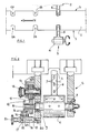
- the continuous paper tapes (1) coming from any unwinding means coupled to longitudinal gumming units and possibly to transversal gumming units of the flaps and heading units, are fed, with known means, to the punching station.
- This station comprises two operating heads (2) positioned one in front of the other, in alignment, and aligned with the opposite sides (3) of the continuous tapes, with respect to the sides of which they take up a substantially right-angled position.
- Each operating head (2) comprises a rotating drum (4) equipped with a tangential support (4′) on which an interchangeable blade (5) is fixed, whose axial position can be easily adjusted with lock nuts (6) operating in longitudinal slits (7) obtained in said support (4′).
- Each rotating drum (4) is supported at the sides by bearings (9) and comprises an elongated, grooved end (10) which is coupled with a sprocket with helical toothing (11) equipped with an end thrust bearing (12).
- the helical sprocket (11) is engaged in a helical gearing (13) coaxial with a conical pinion (14).
- Said conical pinion (14) receives the rotating movement from other members, not illustrated, as they form part of the known technique.
- the rotation axes of said rollers (15) are integral with supports (16), fixed to a body (17) which can slide, guided by at least one tang or longitudinal key (18), along a fixed pin (19).
- the fixed pin (19) is fixed to the supporting structure (20) of the operating head (2).
- the slip of the body (17) along the fixed pin (19) is obtained by means of the knob (21) which, rotating, engages its threaded end (22) in a corresponding threaded hole (23), coaxial to the pin (19).
- each transversal displacement along the grooved end (13) causes a corresponding rotation of the sprocket (11) in circumferential direction.
- Said circumferential displacements consent precise position recordings of each drum (4), carrying blade (5), with respect to the position of the opposite drum (4).
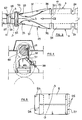
- the continuous tape (1) continues its travel and passes to the subsequent tubular body forming station, i.e. station to form the central closed part of the envelope.
- the tape (1), towed, is inserted in a fixed interchangeable conveyor (29).
- Said conveyor consists of a flat central body (30) equipped with two curved side profiles (31), with progressive variable flow from the entrance point (32) of the tape and the exit point (33).
- Said profiles (31) assume, in the exit point (33), a completely folded shape in substantially parallel position, above the flat central body (30), and form with said central body (30) a slit (34) of identical thickness and width to those of the tubular body of the envelopes in formation.
- the tubular body At the exit of the slit (34), the tubular body has taken up its final conformation and a pressing roller (36) presses the surmounted edges (3) of the flaps (35) to make them perfectly adherent.
- the continuous tape (1) is substantially formed by a sequence of tubular bodies delimited by the rear (27) and front (28) edges, intercalated by intermediate flat zones, laterally profiled.
- the continuous tape is passed into a cutting station.
- Said station comprises a fixed lower transversal blade (37), equipped with means of regulation (38), and an upper transversal blade (39), with means of regulation (42), applied to a rotating roller (40).
- the rotating speed of the roller (40) is such that, each time the cutting edge of the upper movable transversal blade (39) is aligned with and brushes against the cutting edge of the lower fixed transversal blade (37), the continuous tape (1) which slides between them is aligned according to a broken transversal line (41) corresponding to the center line of each punching (24) and indicated in the figure (3).
- the upper movable blade (39) cuts with a net stroke, without producing dust or jagged effects, the continuous tape (1) along the abovementioned broken transversal lines (41).
- the envelopes (8) are thus formed apart from the folding and glueing of the rear flap (25) which is carried out with conventional methods.
- the separating cut of the bags, carried out at right angles to same, is made with the rotating direction of the roller (40), movable blade holder (39), equal to the slip direction of the continuous tape (1) and in collaboration with the lower fixed blade (37), also positioned in the direction of the motion of said tape.
- the regulation of the blades (37) and (39) makes it possible to make net cuts, without tears, without draggings or formations of dust.
- Bags of different lengths are obtained by increasing or decreasing the feed speed of the continuous tape (1), the rotating speed of the roller (40) remaining steady.
Landscapes
- Making Paper Articles (AREA)
Applications Claiming Priority (2)
| Application Number | Priority Date | Filing Date | Title |
|---|---|---|---|
| IT21104/88A IT1217927B (it) | 1988-06-24 | 1988-06-24 | Perfezionamenti a macchine per la formazione di buste a sacco |
| IT2110488 | 1988-06-24 |
Publications (1)
| Publication Number | Publication Date |
|---|---|
| EP0347799A1 true EP0347799A1 (de) | 1989-12-27 |
Family
ID=11176808
Family Applications (1)
| Application Number | Title | Priority Date | Filing Date |
|---|---|---|---|
| EP89111105A Withdrawn EP0347799A1 (de) | 1988-06-24 | 1989-06-19 | Umschlagerzeugungsmaschine |
Country Status (2)
| Country | Link |
|---|---|
| EP (1) | EP0347799A1 (de) |
| IT (1) | IT1217927B (de) |
Cited By (1)
| Publication number | Priority date | Publication date | Assignee | Title |
|---|---|---|---|---|
| DE10023999A1 (de) * | 2000-05-17 | 2001-11-22 | Winkler & Duennebier Ag | Verfahren zur Herstellung von Briefhüllen aus einer bewegten Materialbahn |
Citations (3)
| Publication number | Priority date | Publication date | Assignee | Title |
|---|---|---|---|---|
| DE1185045B (de) * | 1952-05-12 | 1965-01-07 | Marius Berghgracht | Maschine zum Herstellen von Schlauchabschnitten mit Seitenfalten fuer Faltbeutel |
| US4359919A (en) * | 1979-03-29 | 1982-11-23 | Winkler & Dunnebier Maschinenfabrik Und Eisengiesserei Gmbh & Co. Kg | Rotary punch comprising a backup roll bearing on the cutter roll |
| DE3337199A1 (de) * | 1983-10-13 | 1985-05-02 | Chapman Envelopes Ltd., Bromley, Kent | Vorrichtung zur herstellung von umschlagzuschnitten |
-
1988
- 1988-06-24 IT IT21104/88A patent/IT1217927B/it active
-
1989
- 1989-06-19 EP EP89111105A patent/EP0347799A1/de not_active Withdrawn
Patent Citations (3)
| Publication number | Priority date | Publication date | Assignee | Title |
|---|---|---|---|---|
| DE1185045B (de) * | 1952-05-12 | 1965-01-07 | Marius Berghgracht | Maschine zum Herstellen von Schlauchabschnitten mit Seitenfalten fuer Faltbeutel |
| US4359919A (en) * | 1979-03-29 | 1982-11-23 | Winkler & Dunnebier Maschinenfabrik Und Eisengiesserei Gmbh & Co. Kg | Rotary punch comprising a backup roll bearing on the cutter roll |
| DE3337199A1 (de) * | 1983-10-13 | 1985-05-02 | Chapman Envelopes Ltd., Bromley, Kent | Vorrichtung zur herstellung von umschlagzuschnitten |
Cited By (1)
| Publication number | Priority date | Publication date | Assignee | Title |
|---|---|---|---|---|
| DE10023999A1 (de) * | 2000-05-17 | 2001-11-22 | Winkler & Duennebier Ag | Verfahren zur Herstellung von Briefhüllen aus einer bewegten Materialbahn |
Also Published As
| Publication number | Publication date |
|---|---|
| IT1217927B (it) | 1990-03-30 |
| IT8821104A0 (it) | 1988-06-24 |
Similar Documents
| Publication | Publication Date | Title |
|---|---|---|
| US3981213A (en) | Rotary sheet material cutter and creaser | |
| US4076786A (en) | Method for producing container label blanks from a web | |
| US4398903A (en) | Method of and apparatus for making handle bags | |
| US2395352A (en) | Box making machine | |
| US4073485A (en) | Apparatus for making multiple page printed booklets | |
| US4133712A (en) | Apparatus for and method of forming honeycomb material | |
| US3041941A (en) | Manufacture of containers or the like | |
| CA1276655C (en) | Production of paper with decorative, non-rectilinear edges | |
| US2382930A (en) | Laminating apparatus | |
| US2719808A (en) | Process of making shells for foldable veneer boxes | |
| CA1075590A (en) | Slicing web material | |
| SU1121156A1 (ru) | Машина дл изготовлени заготовок упаковочных коробок из картонного полотна | |
| US2423187A (en) | Bag making machine | |
| US1772785A (en) | Art of working cardboard and similar material | |
| US3292473A (en) | Cutting stroke adjusting mechanism | |
| US3773596A (en) | Method and device for manufacturing bag | |
| US4125044A (en) | Rotary cutting apparatus | |
| US2281964A (en) | Method and apparatus for making paper bags | |
| EP0347799A1 (de) | Umschlagerzeugungsmaschine | |
| US3218217A (en) | Apparatus for making cellular material | |
| US4136591A (en) | Apparatus for changing the length of envelope blanks cut from a continuous web | |
| US3677144A (en) | Method and apparatus for manufacturing flat, tubular wrappers | |
| US2837012A (en) | Scoring apparatus | |
| US2949066A (en) | Method and apparatus for creasing blanks | |
| US1707712A (en) | Slide-box-shell machine |
Legal Events
| Date | Code | Title | Description |
|---|---|---|---|
| PUAI | Public reference made under article 153(3) epc to a published international application that has entered the european phase |
Free format text: ORIGINAL CODE: 0009012 |
|
| AK | Designated contracting states |
Kind code of ref document: A1 Designated state(s): AT BE CH DE ES FR GB GR LI LU NL SE |
|
| 17P | Request for examination filed |
Effective date: 19900502 |
|
| 17Q | First examination report despatched |
Effective date: 19910605 |
|
| STAA | Information on the status of an ep patent application or granted ep patent |
Free format text: STATUS: THE APPLICATION IS DEEMED TO BE WITHDRAWN |
|
| 18D | Application deemed to be withdrawn |
Effective date: 19921231 |