EP0347720B1 - Apparatus and method for gray scale display - Google Patents
Apparatus and method for gray scale display Download PDFInfo
- Publication number
- EP0347720B1 EP0347720B1 EP89110678A EP89110678A EP0347720B1 EP 0347720 B1 EP0347720 B1 EP 0347720B1 EP 89110678 A EP89110678 A EP 89110678A EP 89110678 A EP89110678 A EP 89110678A EP 0347720 B1 EP0347720 B1 EP 0347720B1
- Authority
- EP
- European Patent Office
- Prior art keywords
- gray scale
- display
- information
- color
- signals
- Prior art date
- Legal status (The legal status is an assumption and is not a legal conclusion. Google has not performed a legal analysis and makes no representation as to the accuracy of the status listed.)
- Expired - Lifetime
Links
Images


Classifications
-
- G—PHYSICS
- G09—EDUCATION; CRYPTOGRAPHY; DISPLAY; ADVERTISING; SEALS
- G09G—ARRANGEMENTS OR CIRCUITS FOR CONTROL OF INDICATING DEVICES USING STATIC MEANS TO PRESENT VARIABLE INFORMATION
- G09G3/00—Control arrangements or circuits, of interest only in connection with visual indicators other than cathode-ray tubes
- G09G3/20—Control arrangements or circuits, of interest only in connection with visual indicators other than cathode-ray tubes for presentation of an assembly of a number of characters, e.g. a page, by composing the assembly by combination of individual elements arranged in a matrix no fixed position being assigned to or needed to be assigned to the individual characters or partial characters
- G09G3/34—Control arrangements or circuits, of interest only in connection with visual indicators other than cathode-ray tubes for presentation of an assembly of a number of characters, e.g. a page, by composing the assembly by combination of individual elements arranged in a matrix no fixed position being assigned to or needed to be assigned to the individual characters or partial characters by control of light from an independent source
- G09G3/36—Control arrangements or circuits, of interest only in connection with visual indicators other than cathode-ray tubes for presentation of an assembly of a number of characters, e.g. a page, by composing the assembly by combination of individual elements arranged in a matrix no fixed position being assigned to or needed to be assigned to the individual characters or partial characters by control of light from an independent source using liquid crystals
- G09G3/3611—Control of matrices with row and column drivers
-
- G—PHYSICS
- G09—EDUCATION; CRYPTOGRAPHY; DISPLAY; ADVERTISING; SEALS
- G09G—ARRANGEMENTS OR CIRCUITS FOR CONTROL OF INDICATING DEVICES USING STATIC MEANS TO PRESENT VARIABLE INFORMATION
- G09G5/00—Control arrangements or circuits for visual indicators common to cathode-ray tube indicators and other visual indicators
- G09G5/02—Control arrangements or circuits for visual indicators common to cathode-ray tube indicators and other visual indicators characterised by the way in which colour is displayed
- G09G5/028—Circuits for converting colour display signals into monochrome display signals
-
- G—PHYSICS
- G09—EDUCATION; CRYPTOGRAPHY; DISPLAY; ADVERTISING; SEALS
- G09G—ARRANGEMENTS OR CIRCUITS FOR CONTROL OF INDICATING DEVICES USING STATIC MEANS TO PRESENT VARIABLE INFORMATION
- G09G3/00—Control arrangements or circuits, of interest only in connection with visual indicators other than cathode-ray tubes
- G09G3/20—Control arrangements or circuits, of interest only in connection with visual indicators other than cathode-ray tubes for presentation of an assembly of a number of characters, e.g. a page, by composing the assembly by combination of individual elements arranged in a matrix no fixed position being assigned to or needed to be assigned to the individual characters or partial characters
- G09G3/2007—Display of intermediate tones
- G09G3/2018—Display of intermediate tones by time modulation using two or more time intervals
Definitions
- the present invention relates to gray scale displaying capable of a display according to a plurality of luminance data and more particularly relates to an apparatus and a method for a gray scale display capable of displaying color information in accordance with luminance data corresponding to the color information.
- the liquid crystal display (hereinafter to be briefly referred to as "LCD") is enabled to make a half-tone display by being controlled such that displaying of statuses and non-displaying of statuses therein are switched at intervals of a certain number of frame cycles.
- LCD liquid crystal display
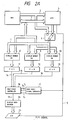
- FIG. 2A is a block diagram of a display circuit in a personal computer showing a prior art example.
- reference numeral 1 denotes a central processing unit (hereinafter to be briefly referred to as "MPU")
- 2 denotes an address bus
- 3 denotes a data bus
- 4 denotes an LCD timing controller (hereinafter to be briefly referred to as "LCTC")
- 5 denotes a frame line marker signal (hereinafter to be briefly referred to as "FLM signal”)
- 6 denotes a selector
- 7 denotes a compound bus
- 8 - 10 denote display memories R, G, and B, respectively.
- 11 - 13 denote parallell-to-serial converters (each block thereof in the drawing is briefly labeled "P ⁇ S")
- 14 - 16 denote display signal lines R, G, and B, respectively
- 17 denotes a gray scale signal generator
- 18 denotes a gray scale controller
- 19 denotes a video signal line
- 20 denotes a display data decoder
- 21 denotes a liquid crystal display (hereinafter to be briefly referred to as "LCD"). Operation of the circuit of FIG. 2 will be described below.
- the selector 6 selects the address bus 2. Thereby, the MPU 1 is enabled to update or read the contents of the display memories 8 - 10.
- the selector 6 selects display address information which is output from the LCTC 4. Accordingly, the contents of the display memories 8 - 10 are read out in the sequence of scanning according to the information on the compound bus 7 and these are delivered to their respective parallel-to-serial converters 11 - 13. The information is thereby converted into R, G, and B display signals on lines 14 - 16, respectively, and are supplied to the gray scale controller 18 as display information.
- the gray scale signal generator 17 delivers eight kinds of gray scale signals (Y0 - Y7) to the gray scale controller 18.
- Y0 for example, provides the darkest display and Y7 provides the brightest display.
- the gray scale controller 18 selects a gray scale signal corresponding to the display information for eight colors conveyed by the display signals 14 - 16 and outputs it to the video signal line 19.
- the circuit is enabled to emulate the eight-color display with a monochromatic display in eight gray scales.
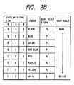
- the correspondence between colors and gray scales are shown in FIG. 2B.
- the video signal on line 19, including such gray scale display information, is converted by the display decoder 20 into information that can be displayed on the LCD 21.
- the LCD 21 makes a display according to the delivered information, with frame synchronization taken from the FLM signal 5. What has just been described is the outline of the operation of the display circuit enabling the LCD to make a display of eight gray scales.
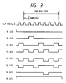
- FIG. 3 is a timing chart of the gray scale signals Y0 - Y7 generated by the gray scale signal generator 17.
- the reference signal is the FLM signal on line 5 at one frame cycle (approximately 70 Hz). Seven frame cycles are used as a gray scale period.
- the display for the signal Y1 is turned ON at the rate of 1/7. That is, the display is turned ON during one scan out of seven scans of the picture and it is turned OFF during the period of the remaining six scans. Thereby, the duty ratio of picture displaying is changed and a half tone display can be achieved.
- the signals Y2 - Y6 are the signals that also change the duty ratio so that half tone display may be achieved similarly.
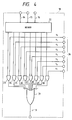
- FIG. 4 is a block diagram showing the gray scale controller 18.
- circuit blocks and signal lines corresponding to those in FIG. 2 are denoted by corresponding reference numerals.
- reference numeral 22 denotes a decoder of a three-bit structure
- 23 - 30 denote AND circuits
- 31 denotes an OR circuit.
- the decoder 22 decodes the color information conveyed by the R, G, B display signal lines 14 - 16 and turns ON only the AND circuit corresponding to that color. For example, if the color information is that for the black color, the AND circuit 23 is turned ON, or if it is for the blue color, the AND circuit 24 is turned ON. Therefore, the OR circuit 31 outputs the gray scale signal corresponding to the color information to the video signal line 19.
- the description made so far is of the operation of the gray scale controller 18 converting color information into gray scale information.
- a gray scale display to achieve color emulation can be performed by a monochromatic display apparatus if the color display circuit is additionally provided with the gray scale signal generator 17 and gray scale controller 18.
- implementation of portable office automation equipment can be advanced taking over the great assets of application software intended for color display.
- gray scales for example, of Y0 - Y3 may be difficult to discriminate in LCDs manufactured by a second manufacturer because of uneven differences in luminance between the adjoining gray scales. Therefore, when using LCDs manufactured by the second manufacturer, it becomes necessary to change the timing of gray scale cycles for the gray scale signals (Y0 - Y7) and also to change the circuit in the gray scale signal generator accordingly so that suitable luminance differences may be obtained, and this was a difficulty in effective product development.
- the circuit converts digital signals representing color information into analog voltage level signals applied to a monochrome CRT monitor.
- a character generator supplies character information signals and an attribute register supplies color attribute signals for the foreground character information and also color attribute signals for the background.
- Four bits of the color attribute signals define 16 colors, namely three bits for combining the basic colors read, green and blue and one intensity bit for making the eight color combinations lighter or darker.
- a multiplexer combines the character information signals (which are in the form of foreground/background bits) with the color attribute signals. This video signal is normally supplied to a color display. In cases where only a monochrome display is available the 16 colors are transformed into 16 gray scale levels.
- the eight lighter colors when used as a background-color black may be shifted into the direction of black color.
- the level shift is accomplished by using the already mentioned foreground/background signals once more for influencing a voltage divider which attributes a gray scale to the four bits of red, green, blue and intensity.
- the elder application according to EP-A-281 502 discloses another method for replacing single colors by gray scale levels. It is pointed out as a problem that the colors are normally edited without taking into consideration a possible black-white display.
- a gray scale memory is added to the conventional color memory.
- the available colors are stored in the color memory in a predetermined sequence. Each color is evaluated in terms of its luminance, i.e. the luminance value of each used color is calculated. Each luminance value is assigned to a gray scale level in such a manner that the contrast is enhanced.
- the assigned gray scale levels are stored in the gray scale memory in the same sequence as the original colors are stored in the color memory.
- the gray scale levels are read out in parallel to the color values and may be supplied to a black-white monitor. A selection performed by the user and adjustable to an arbitrary black-white display is not disclosed.
- An object of the present invention is to solve the above described problems and, accordingly, to provide an apparatus and a method for gray scale displaying in which multiple gray scales for luminance for any color information are provided, any one of which is selectable at will.
- Another object of the present invention is to provide a monochromatic emulation system capable of converting the color information provided with such gray scales into corresponding monochromatic gray scale information.
- a further object of the present invention is to provide an apparatus and a method for gray scale displaying adapted to be favorably compatible with application software intended for color displaying.
- a still further object of the present invention is to provide an apparatus and a method for gray scale displaying suitable for use in display devices whose relationships between the duty ratio in displaying and luminance information are different from one another.
- the present invention provides an apparatus as claimed in claim 1 and a method as claimed in claim 6.
- a gray scale displaying apparatus stores information for turning the display means on and off during each frame cycle within one cycle, which has been formed of a plurality of frames, corresponding to each color represented by the color information, generates gray scales by updating or reading the stored contents for each frame, and, in response to the display information, selects and displays the output of the gray scales corresponding to the display information
- the user to optionally select any gray scale signal out of a plurality of gray scale signals that are previously prepared by a gray scale selector or a gray scale selectable generator thereof and apply the selected gray scale signal to each color.
- the gray scale display apparatus when the gray scale display apparatus is compatibly used for color application software, the user is enabled to connect the color to the gray scale in any desired relationship.
- the gray scale signal suitable for the characteristics of each specific display means can be selected out of gray scale signals whose number is larger than the number of colors represented by the display information, whereby the variances in the characteristics can be coped with.
- FIG. 1 is a block diagram showing a personal computer display circuit to which the present invention is applied.
- circuit blocks and signals corresponding to those in FIG. 2 are denoted by corresponding reference numerals.
- reference numeral 32 denotes a gray scale selector
- 33 denotes a gray scale signal line
- 34 denotes a selected gray scale signal line.
- the gray scale selector 32 receives gray scale select information through an address bus 2 and a data bus 3, and the selector selects information on the gray scale signal line 33 and delivers the selected signal to a gray scale controller 18 through the selected gray scale signal line 34.
- the gray scale controller 18 receives color display information stored in display memories 8 - 10 through parallel-to-serial converters 11 - 13, and the controller selects the gray scale information on the selected gray scale signal line 34 corresponding to the above color display information and outputs the selected information to a gray scale display signal line 19. Further, a display information decoder 20 generates visible information and thereby a gray scale display is made on an LCD 21. Thus, by setting up information in the gray scale selector 32, the correspondence between the color for a color display and the luminance for a gray scale display can be controlled at will.
- the gray scale selector 32 as the principal portion of the present invention will be described below in detail with reference to FIG. 5.
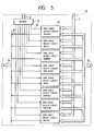
- FIG. 5 is a block diagram showing details of the gray scale selector 32.
- circuit blocks and signal lines having corresponding functions to those in FIG. 1 are denoted by corresponding reference numerals.
- reference numeral 35 denotes a decoder
- 36 denotes a decoded output signal
- 37 denotes a gray scale select circuit
- 38 denotes a selected gray scale signal line.
- the decoder 35 decodes information on the address bus 2 and outputs the decoded signals to eight gray scale select circuits provided for the eight colors. Since, for example, the selected gray scale signal line 38 delivers the gray scale information corresponding to "black", the decoded output signal line 36 is assigned to the address for establishing the gray scale information corresponding to "black”.
- the gray scale select circuit 37 is adapted to select the information corresponding to "black” out of the information on the gray scale signal line 33 and to output it to the selected gray scale signal line 38.
- the circuit blocks in FIG. 5 drawn below the gray scale select circuit 37 in succession are gray scale select circuits for blue, green, sky blue, red, purple, yellow, and white.
- the gray scale select circuit 37 will be described below with reference to FIG. 6A.
- FIG. 6A is a drawing showing details of the gray scale select circuit 37.
- circuit blocks and signal lines having corresponding functions to those in FIG. 5 are denoted by corresponding reference numerals.
- 39 denotes a three-bit latch circuit which retains information of D2 - D0 delivered from the data bus 3 at the timing given by the decoded signal line 36. This information is delivered to the gray scale controller 18 equivalent to those of gray scale controller 18 shown in FIG. 4.
- one of the gray scale signals Y0 - Y7 on the gray scale signal line 33 is selected and delivered to the selected gray scale signal line 38.
- the correspondence for the black color between the values in the latch circuit 39 and gray scales in the gray scale controller 18 within the gray scale select circuit 37 is shown in FIG. 6B.
- the gray scale allotted to the black color can be optionally selected from Y0 - Y7 according to the value input to the latch 39.
- a suitable gray scale to other color correspondence can be freely selected out of Y0 - Y7.
- the present invention is not limited to the above described example. As one of other examples, the case where the invention is applied to a plasma display apparatus (hereinafter to be briefly referred to as "PDP") will be described below as a second embodiment.
- PDP plasma display apparatus
- the PDP Since the PDP has a higher response speed than the LCD, when it is used at the timing of the gray scale signal Y1 shown in FIG. 3, its flickering becomes conspicuous and it is not practically usable. Therefore, to attain eight gray scales, a PDP capable of displaying four gray scales is used. Then, it becomes necessary to display half tone by switching two gray scales of different luminance at intervals of one picture scan. The case where the present invention is applied to the above described manner of operation will be described below with reference to FIG. 7A showing such an arrangement.
- FIG. 7A is a block diagram showing a display circuit using a PDP.
- circuit blocks and signal lines having corresponding functions to those in FIG. 1 are denoted by corresponding reference numerals.
- reference numeral 40 denotes a gray scale selectable generator
- 41 and 47 denote selected gray scale signal lines
- 42 denotes a gray scale controller
- 43 and 44 denote gray scale display signal lines (PD0 and PD1)
- 45 denotes a display data decoder
- 46 denotes a PDP capable of displaying four gray scales (for example, Matsushita-made MD400F640PD4).
- the gray scale controller 42 converts the information on the display signal lines 14 - 16 into gray scale information according to information on the selected gray scale signal lines 41 and 47 output from the gray scale selectable generator 40.
- the gray scale information is of a two-bit amount because it is for displaying four gray scales and it is transmitted through gray scale display signal lines 43 and 44. Representing the information on the gray scale signal line 43 by PD0 and that on the signal line 44 by PD1, relationships between these and gray scale displays are shown in FIG. 7B.
- the information is converted into visible information in the display data decoder 45 and displayed on the PDP 46.
- gray scale selectable generator 40 As the principal portion of the present invention.
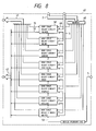
- FIG. 8 is a drawing showing details of the gray scale selectable generator 40.
- circuit blocks and signal lines having corresponding functions to those in FIG. 7A are denoted by corresponding reference numerals.
- reference numeral 48 denotes a decoder
- 49 denotes a decoded signal line for establishing the gray scale for "black”
- 50 denotes a gray scale select circuit 50 for "black”
- 51 and 52 denote selected gray scale signal lines for PD0 and PD1, respectively
- 53 denotes a frame switching signal for discriminating and switching between an odd frame and an even frame.
- the decoder 48 decodes information on the address bus 2 and outputs the decoded signals to the eight gray scale select circuits.
- the decoded output signal line 49 is assigned to the address for establishing the gray scale information corresponding to "black".
- the gray scale information for "black” is constituted of one portion of the gray scale information displayed on an even numbered frame and the other portion of the gray scale information displayed on an odd numbered frame. These portions are switched at intervals of one frame with the use of the frame switching signal 53 provided by dividing the frequency of the FLM signal on line 5 by two and are output to the selected gray scale signal lines 51 and 52.
- the circuit blocks drawn below the gray scale select circuit 50 in succession are gray scale select circuits for blue, green, sky blue, red, purple, yellow, and white.
- the selected gray scale signal line 41 conveys PD0 information
- the signal line 47 conveys PD1 information, out of the gray scale information for eight colors.
- the gray scale select circuit 50 will be described below with reference to FIG. 9A.
- FIG. 9A is a drawing showing details of the gray scale select circuit 50, in which circuit blocks and signal lines having corresponding function to that those in FIG. 8 are denoted by corresponding reference numerals.
- reference numeral 54 denotes a four-bit latch circuit and 55 denotes a double-set selector.
- the latch circuit 54 retains information D3 - D0 received from the data bus 3 at the timing given by the decoded signal line 49. The retained information is delivered to the selector 55.
- the selector 55 when the frame switching signal 53 indicates an odd frame, selects the information on Q0 and Q2 as shown in FIG. 9A and delivers it to the selected gray scale signal lines 51 and 52, respectively.
- the present invention can be easily embodied for gray scale displaying where such a display having a high response speed as a PDP is used. Therefore, the same effects as obtained in the first embodiment can be obtained from this embodiment.
- FIG. 10 is a timing chart of the gray scale signal line 33 output from the gray scale signal generator 17.
- the gray scale signal generator 17 uses a nine-clock period of the FLM signal as the gray scale cycle to thereby generate 10 gray scale signals. These gray scale signals can be easily obtained by a simple circuit combination including a mod-9 counter.
- the gray scale selector 32 selects eight gray scale signals suitable for the display on the LCD 21 out of the 10 gray scale signals.
- the basic structure of the gray scale selector 32 is the same as that of FIG. 5, but the structure of the gray scale select circuit 37 is different, and therefore, description of it will be given below referring to FIG. 11.
- FIG. 11 is a detailed drawing showing the gray scale select circuit 37 for selecting one out of the 10 gray scale signals.
- circuit blocks and signal lines having corresponding functions to those in FIG. 5 are denoted by corresponding reference numerals.
- reference numeral 56 denotes a four-bit latch circuit and 57 denotes a multiple gray scale controller.
- the latch circuit 56 retains gray scale select information formed of four bits and delivers it to the multiple gray scale controller 57.
- the multiple gray scale controller 57 selects one of the 10 gray scale signals and outputs it to the selected gray scale signal line 38.
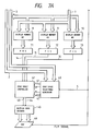
- FIG. 12 is a drawing showing details of the multiple gray scale controller 57.
- circuit blocks and signal lines having corresponding functions to those in FIG. 11 are denoted by corresponding reference numerals.
- reference numeral 58 denotes a four-bit decoder
- 59 denotes an AND circuit
- 60 denotes an OR circuit having 10 inputs.
- the decoder 58 decodes gray scale select information and outputs a decoded signal corresponding to the selected gray scale signal to the AND circuits 59.
- one of the 10 gray scale signals is selected by means of the ten AND circuits 58 and one OR circuit 60, and the selected signal is output to the selected gray scale signal line 38.
- the multiple gray scale controller 57 can select the information of the gray scale signal lines 33 at will. Therefore, it can select the gray scale signal corresponding to each of eight colors from the ten kinds of gray scale signals.
- gray scales are selected out of ten gray scales according to characteristics of the LCD used. For example, when employing an LCD from one manufacturer, the best gray scale display can be achieved by using the gray scale signals Y0, Y3 - Y9 shown in FIG. 10. Meanwhile, in the case of an LCD from another manufacturer, the best gray scale display can be achieved by using the gray scale signal Y0 - Y6, Y9.
- the present embodiment makes it possible to obtain the best gray scale display without the need for a change in the hardware but just by a change in the arrangement of the software according to the characteristics of the LCD used. Since, in particular, characteristics of LCDs change with the improvement in the quality of display, man-hours for development of hardware for display apparatuses using LCDs can be reduced substantially.
- the present invention is not limited to the above described embodiment; that is, the selectable number of gray scales may be larger than ten.
- the gray scale pattern of the gray scale signal shown in FIG. 10 as it is may be stored in a storage device (RAM or ROM) so that the gray scale signals are generated thereby.
- This system may be described below as a fourth embodiment.
- FIG. 13 is a block diagram showing a portion of a display circuit.
- circuit blocks and signal lines having corresponding functions to those in FIG. 1 are denoted by corresponding reference numerals.
- reference numeral 61 denotes a hexadecimal (mod-16) counter
- 62 denotes a counter output signal line
- 63 denotes a gray scale selectable generator in the present embodiment.
- the gray scale selectable generator 63 by means of the address bus 2 and the data bus 3, sets up the gray scale pattern information in the internal RAM.
- the above gray scale pattern information is selected according to information on the counter output line 62 of the hexadecimal counter 61 for the FLM signal 5, and it is output to the selected gray scale signal line 34.
- the gray scale controller 18 is enabled to output the gray scale signal corresponding to each display color.
- the gray scale selectable generator 63 as the central portion of the present embodiment will be described below in detail.
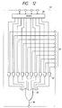
- FIG. 14 is a drawing showing details of the gray scale selectable generator 63.
- circuit blocks and signal lines having corresponding functions to those in FIG. 13 are denoted by corresponding reference numerals.
- reference numeral 64 denotes a decoder
- 65 denotes a selector
- 66 denotes a 16 words x 8 bits RAM.
- Each address of the RAM 66 corresponds to one frame, and the data at the address represents ON/OFF information of the display data for each color in the frame.
- the decoder 64 makes the decoded signal effective when the address on the address bus 2 indicates the address information in the RAM 66.
- the selector 65 selects the address bus 2 so that the information on the data bus 3 is set up in the RAM 66.
- the selector 65 selects the counter output line 62 so that information set in the RAM 66 is read out. Since, at this time, the address in the RAM 66 is designated by the output of the hexadecimal counter 61, the address is renewed for each frame.
- the established data at each of the addresses 0, 1, ... , 15 is read out in succession from the RAM 66 for each frame. Since each bit of the established data is the ON/OFF information for displaying each color as described above, the same bits at 16 addresses constitute the gray scale pattern of 16 frame cycles.
- the output information of the RAM 66 is supplied to the selected gray scale signal line 34 as eight gray scale signals corresponding to the display color.
- 16 frames constitute the gray scale cycle and 17 kinds of gray scale signals can be generated.
- the data in the RAM 66 can be optionally altered, any desired gray scale can be assigned to each display color.
- the embodiment has been described above using a RAM, the same effects can be easily obtained using a ROM. Then, it is impossible to change the gray scale pattern by software, but the requirement can be met by exchanging the ROM for another ROM having different contents. Further, as is apparent from the above description, by increasing the number of addresses in the RAM, the number of gray scales to be selected from can be increased, and by expanding the width of the data, gray scales for a larger number of colors than eight can be easily obtained.
- FIG. 15 is an example of the method of using the present invention.
- AP soft application software program
- the correspondence between color and gray scale is established in advance. Namely, it is a characteristic of this embodiment that it provides the user with the means to establish information of such a correspondence that the user considers suitable according to the coloring in the AP soft to be executed.
- FIG. 16 shows an example of use concerned with some LCDs and corresponding gray scales.
- the present invention since the user can select the correspondence between the displayed colors and the gray scale information, the effect can be obtained, when executing application software intended for color displaying, that optimum color emulation with gray scale displaying can be achieved. Further, since the present invention can support a plurality of LCDs and the like having different characteristics concerning duty ratios for displaying and luminance, utility of the display apparatus to general purposes can be enhanced, and efficiency in the development of hardware can be improved. Besides, since the gray scale pattern of gray scale information can be set in a storage device, the gray scale information faithfully meeting characteristics of the aforesaid LCDs or the like can be generated so that a display apparatus of high versatility can be provided.
Landscapes
- Engineering & Computer Science (AREA)
- Physics & Mathematics (AREA)
- Computer Hardware Design (AREA)
- General Physics & Mathematics (AREA)
- Theoretical Computer Science (AREA)
- Chemical & Material Sciences (AREA)
- Crystallography & Structural Chemistry (AREA)
- Liquid Crystal Display Device Control (AREA)
- Control Of Indicators Other Than Cathode Ray Tubes (AREA)
- Liquid Crystal (AREA)
- Controls And Circuits For Display Device (AREA)
Description
- The present invention relates to gray scale displaying capable of a display according to a plurality of luminance data and more particularly relates to an apparatus and a method for a gray scale display capable of displaying color information in accordance with luminance data corresponding to the color information.
- Recently, miniaturization of office automation equipment has been extensively developed, keeping pace with the advance of the large scale integrated circuit technology and portable personal computers and the like and steadily extending their market. The chief factor in development of portable equipment is improvements in the display apparatus. Flat display devices such as liquid crystal, plasma, and EL (electro-luminescent) displays are superseding the conventional CRT (cathode ray tube) and are becoming important. The technology for gray scale display for emulating color display information with a monochromatic display, in particular, is useful in the sense that existing software can be used. As disclosed, for example, in Japanese Laid-open Patent Publication JP-A-5857192, the liquid crystal display (hereinafter to be briefly referred to as "LCD") is enabled to make a half-tone display by being controlled such that displaying of statuses and non-displaying of statuses therein are switched at intervals of a certain number of frame cycles. Below will be described such a gray scale display with reference to FIG. 2.
- FIG. 2A is a block diagram of a display circuit in a personal computer showing a prior art example. Referring to the figure,
reference numeral 1 denotes a central processing unit (hereinafter to be briefly referred to as "MPU"), 2 denotes an address bus, 3 denotes a data bus, 4 denotes an LCD timing controller (hereinafter to be briefly referred to as "LCTC"), 5 denotes a frame line marker signal (hereinafter to be briefly referred to as "FLM signal"), 6 denotes a selector, 7 denotes a compound bus, and 8 - 10 denote display memories R, G, and B, respectively. Further, 11 - 13 denote paralell-to-serial converters (each block thereof in the drawing is briefly labeled "P→S"), 14 - 16 denote display signal lines R, G, and B, respectively, 17 denotes a gray scale signal generator, 18 denotes a gray scale controller, 19 denotes a video signal line, 20 denotes a display data decoder, and 21 denotes a liquid crystal display (hereinafter to be briefly referred to as "LCD"). Operation of the circuit of FIG. 2 will be described below. - When the MPU 1 accesses the display memories 8 - 10, the
selector 6 selects theaddress bus 2. Thereby, the MPU 1 is enabled to update or read the contents of the display memories 8 - 10. When the contents of the display memories 8 - 10 are to be displayed on theLCD 21, theselector 6 selects display address information which is output from theLCTC 4. Accordingly, the contents of the display memories 8 - 10 are read out in the sequence of scanning according to the information on thecompound bus 7 and these are delivered to their respective parallel-to-serial converters 11 - 13. The information is thereby converted into R, G, and B display signals on lines 14 - 16, respectively, and are supplied to thegray scale controller 18 as display information. Meanwhile, the grayscale signal generator 17 delivers eight kinds of gray scale signals (Y0 - Y7) to thegray scale controller 18. Of these gray scale signals, Y0, for example, provides the darkest display and Y7 provides the brightest display. Thegray scale controller 18 selects a gray scale signal corresponding to the display information for eight colors conveyed by the display signals 14 - 16 and outputs it to thevideo signal line 19. Thereby, the circuit is enabled to emulate the eight-color display with a monochromatic display in eight gray scales. The correspondence between colors and gray scales are shown in FIG. 2B. The video signal online 19, including such gray scale display information, is converted by thedisplay decoder 20 into information that can be displayed on theLCD 21. TheLCD 21 makes a display according to the delivered information, with frame synchronization taken from theFLM signal 5. What has just been described is the outline of the operation of the display circuit enabling the LCD to make a display of eight gray scales. - Below will be described detailed operations of the gray
scale signal generator 17 and thegray scale controller 18 with which the present invention is most concerned. - FIG. 3 is a timing chart of the gray scale signals Y0 - Y7 generated by the gray
scale signal generator 17. The reference signal is the FLM signal online 5 at one frame cycle (approximately 70 Hz). Seven frame cycles are used as a gray scale period. For example, the display for the signal Y1 is turned ON at the rate of 1/7. That is, the display is turned ON during one scan out of seven scans of the picture and it is turned OFF during the period of the remaining six scans. Thereby, the duty ratio of picture displaying is changed and a half tone display can be achieved. The signals Y2 - Y6 are the signals that also change the duty ratio so that half tone display may be achieved similarly. - Details of the operation of the
gray scale controller 18 will be described below with reference to FIG. 4. - FIG. 4 is a block diagram showing the
gray scale controller 18. In the figure, circuit blocks and signal lines corresponding to those in FIG. 2 are denoted by corresponding reference numerals. Referring to FIG. 4,reference numeral 22 denotes a decoder of a three-bit structure, 23 - 30 denote AND circuits, and 31 denotes an OR circuit. Thedecoder 22 decodes the color information conveyed by the R, G, B display signal lines 14 - 16 and turns ON only the AND circuit corresponding to that color. For example, if the color information is that for the black color, theAND circuit 23 is turned ON, or if it is for the blue color, theAND circuit 24 is turned ON. Therefore, theOR circuit 31 outputs the gray scale signal corresponding to the color information to thevideo signal line 19. The description made so far is of the operation of thegray scale controller 18 converting color information into gray scale information. - As described above, a gray scale display to achieve color emulation can be performed by a monochromatic display apparatus if the color display circuit is additionally provided with the gray
scale signal generator 17 andgray scale controller 18. Thus, implementation of portable office automation equipment can be advanced taking over the great assets of application software intended for color display. - In the above described prior art, the correspondence between the color information and the luminance information was fixed. Therefore, there was a problem, when gray scale displaying was conducted using some existing application software intended to produce color information in which characters in "blue" color were frequently used with the background in "black" color, the difference in the luminance between the color of the characters and the color of the background became so small that the characters were difficult to detect. Further, the relationship between the duty ratio dependent on the gray scale cycle and the luminance differs with the characteristics of the LCD used. More particularly, the gray scale signals shown in FIG. 3 may be suitable for LCDs manufactured by a first manufacturer, but gray scales, for example, of Y0 - Y3 may be difficult to discriminate in LCDs manufactured by a second manufacturer because of uneven differences in luminance between the adjoining gray scales. Therefore, when using LCDs manufactured by the second manufacturer, it becomes necessary to change the timing of gray scale cycles for the gray scale signals (Y0 - Y7) and also to change the circuit in the gray scale signal generator accordingly so that suitable luminance differences may be obtained, and this was a difficulty in effective product development.
- A similar contrast problem arises in a converter which is known from WO-A- 8603614. The circuit converts digital signals representing color information into analog voltage level signals applied to a monochrome CRT monitor. A character generator supplies character information signals and an attribute register supplies color attribute signals for the foreground character information and also color attribute signals for the background. Four bits of the color attribute signals define 16 colors, namely three bits for combining the basic colors read, green and blue and one intensity bit for making the eight color combinations lighter or darker. A multiplexer combines the character information signals (which are in the form of foreground/background bits) with the color attribute signals. This video signal is normally supplied to a color display. In cases where only a monochrome display is available the 16 colors are transformed into 16 gray scale levels. In order to enhance the contrast between foreground information and the background, the eight lighter colors when used as a background-color black, i.e. their range of gray scale levels, may be shifted into the direction of black color. The level shift is accomplished by using the already mentioned foreground/background signals once more for influencing a voltage divider which attributes a gray scale to the four bits of red, green, blue and intensity.
- The elder application according to EP-A-281 502 discloses another method for replacing single colors by gray scale levels. It is pointed out as a problem that the colors are normally edited without taking into consideration a possible black-white display. For enhancing the contrast of a black-white display, a gray scale memory is added to the conventional color memory. The available colors are stored in the color memory in a predetermined sequence. Each color is evaluated in terms of its luminance, i.e. the luminance value of each used color is calculated. Each luminance value is assigned to a gray scale level in such a manner that the contrast is enhanced. The assigned gray scale levels are stored in the gray scale memory in the same sequence as the original colors are stored in the color memory. In operation, the gray scale levels are read out in parallel to the color values and may be supplied to a black-white monitor. A selection performed by the user and adjustable to an arbitrary black-white display is not disclosed.
- An object of the present invention is to solve the above described problems and, accordingly, to provide an apparatus and a method for gray scale displaying in which multiple gray scales for luminance for any color information are provided, any one of which is selectable at will.
- Another object of the present invention is to provide a monochromatic emulation system capable of converting the color information provided with such gray scales into corresponding monochromatic gray scale information.
- A further object of the present invention is to provide an apparatus and a method for gray scale displaying adapted to be favorably compatible with application software intended for color displaying.
- A still further object of the present invention is to provide an apparatus and a method for gray scale displaying suitable for use in display devices whose relationships between the duty ratio in displaying and luminance information are different from one another.
- To achieve the above enumerated objects, the present invention provides an apparatus as claimed in
claim 1 and a method as claimed inclaim 6. - A gray scale displaying apparatus according to a preferred embodiment of the present invention stores information for turning the display means on and off during each frame cycle within one cycle, which has been formed of a plurality of frames, corresponding to each color represented by the color information, generates gray scales by updating or reading the stored contents for each frame, and, in response to the display information, selects and displays the output of the gray scales corresponding to the display information
- According to the present invention, it is possible for the user to optionally select any gray scale signal out of a plurality of gray scale signals that are previously prepared by a gray scale selector or a gray scale selectable generator thereof and apply the selected gray scale signal to each color.
- Therefore, when the gray scale display apparatus is compatibly used for color application software, the user is enabled to connect the color to the gray scale in any desired relationship. When using display means of different characteristics, the gray scale signal suitable for the characteristics of each specific display means can be selected out of gray scale signals whose number is larger than the number of colors represented by the display information, whereby the variances in the characteristics can be coped with.
- The foregoing and other objects, advantages, manner of operation and novel features of the present invention will be understood from the following detailed description when read in connection with the accompanying drawings.
-
- FIG. 1 is a block diagram of a display circuit showing an embodiment of the present invention;
- FIG. 2A is a block diagram showing a prior art example;
- FIG. 2B is an explanatory drawing showing correspondence between colors and gray scale signals;
- FIG. 3 is a timing chart for gray scale signals;
- FIG. 4 is a detailed drawing of a gray scale controller for use in the system of FIG. 2A;
- FIG. 5 is a detailed drawing of a gray scale selector in FIG. 1;
- FIG. 6A is a detailed drawing of a gray scale select circuit in FIG. 5;
- FIG. 6B is an explanatory drawing of gray scale select information;
- FIG. 7A is a block diagram showing a second embodiment of the present invention;
- FIG. 7B is an explanatory drawing showing correspondence between display signals of a PDP and gray scale displays;
- FIG. 8 is a detailed drawing of a gray scale selector in FIG. 7A;
- FIG. 9A is a detailed drawing of a gray scale select circuit in FIG. 8;
- FIG. 9B is an explanatory drawing of gray scale select information;
- FIG. 10 is a timing chart of gray scale signals in a third embodiment of the present invention;
- FIG. 11 is a detailed drawing of a gray scale select circuit;
- FIG. 12 is a detailed drawing of a gray scale controller in FIG. 11;
- FIG. 13 is a block diagram showing a fourth embodiment of the present invention;
- FIG. 14 is a detailed drawing of a gray scale selector in FIG. 13; and
- FIG. 15 and FIG. 16 are flow charts showing examples of use of the present invention.
- An embodiment of the present invention will be described below with reference to FIG. 1.
- FIG. 1 is a block diagram showing a personal computer display circuit to which the present invention is applied. In this figure, circuit blocks and signals corresponding to those in FIG. 2 are denoted by corresponding reference numerals. Referring to FIG. 1,
reference numeral 32 denotes a gray scale selector, 33 denotes a gray scale signal line, and 34 denotes a selected gray scale signal line. Thegray scale selector 32 receives gray scale select information through anaddress bus 2 and adata bus 3, and the selector selects information on the grayscale signal line 33 and delivers the selected signal to agray scale controller 18 through the selected grayscale signal line 34. Thegray scale controller 18 receives color display information stored in display memories 8 - 10 through parallel-to-serial converters 11 - 13, and the controller selects the gray scale information on the selected grayscale signal line 34 corresponding to the above color display information and outputs the selected information to a gray scaledisplay signal line 19. Further, adisplay information decoder 20 generates visible information and thereby a gray scale display is made on anLCD 21. Thus, by setting up information in thegray scale selector 32, the correspondence between the color for a color display and the luminance for a gray scale display can be controlled at will. - The
gray scale selector 32 as the principal portion of the present invention will be described below in detail with reference to FIG. 5. - FIG. 5 is a block diagram showing details of the
gray scale selector 32. In the figure, circuit blocks and signal lines having corresponding functions to those in FIG. 1 are denoted by corresponding reference numerals. Referring to FIG. 5,reference numeral 35 denotes a decoder, 36 denotes a decoded output signal, 37 denotes a gray scale select circuit, and 38 denotes a selected gray scale signal line. Thedecoder 35 decodes information on theaddress bus 2 and outputs the decoded signals to eight gray scale select circuits provided for the eight colors. Since, for example, the selected grayscale signal line 38 delivers the gray scale information corresponding to "black", the decodedoutput signal line 36 is assigned to the address for establishing the gray scale information corresponding to "black". Further, the gray scaleselect circuit 37 is adapted to select the information corresponding to "black" out of the information on the grayscale signal line 33 and to output it to the selected grayscale signal line 38. The circuit blocks in FIG. 5 drawn below the gray scaleselect circuit 37 in succession are gray scale select circuits for blue, green, sky blue, red, purple, yellow, and white. - The gray scale
select circuit 37 will be described below with reference to FIG. 6A. - FIG. 6A is a drawing showing details of the gray scale
select circuit 37. In the figure, circuit blocks and signal lines having corresponding functions to those in FIG. 5 are denoted by corresponding reference numerals. Referring to FIG. 6A, 39 denotes a three-bit latch circuit which retains information of D2 - D0 delivered from thedata bus 3 at the timing given by the decodedsignal line 36. This information is delivered to thegray scale controller 18 equivalent to those ofgray scale controller 18 shown in FIG. 4. Thus, one of the gray scale signals Y0 - Y7 on the grayscale signal line 33 is selected and delivered to the selected grayscale signal line 38. The correspondence for the black color between the values in thelatch circuit 39 and gray scales in thegray scale controller 18 within the gray scaleselect circuit 37 is shown in FIG. 6B. As is apparent from this figure, the gray scale allotted to the black color can be optionally selected from Y0 - Y7 according to the value input to thelatch 39. Similarly, a suitable gray scale to other color correspondence can be freely selected out of Y0 - Y7. - Therefore, while the correspondence between colors and gray scales was fixed as shown in FIG. 2B when a color application software was executed in the prior art personal computer with a monochromatic display, a suitable correspondence between colors and gray scales according to the coloring employed in the application software can be selected in the present embodiment. More particularly, while the black color is always assigned the darkest gray scale Y0 according to FIG. 2B in the prior art, an optional one can be selected from Y0 - Y7 in the present embodiment. Hence, whatever coloring is made, the most suitable color emulation can be achieved.
- The present invention is not limited to the above described example. As one of other examples, the case where the invention is applied to a plasma display apparatus (hereinafter to be briefly referred to as "PDP") will be described below as a second embodiment.
- Since the PDP has a higher response speed than the LCD, when it is used at the timing of the gray scale signal Y1 shown in FIG. 3, its flickering becomes conspicuous and it is not practically usable. Therefore, to attain eight gray scales, a PDP capable of displaying four gray scales is used. Then, it becomes necessary to display half tone by switching two gray scales of different luminance at intervals of one picture scan. The case where the present invention is applied to the above described manner of operation will be described below with reference to FIG. 7A showing such an arrangement.
- FIG. 7A is a block diagram showing a display circuit using a PDP. In the figure, circuit blocks and signal lines having corresponding functions to those in FIG. 1 are denoted by corresponding reference numerals. Referring to the figure,
reference numeral 40 denotes a gray scale selectable generator, 41 and 47 denote selected gray scale signal lines, 42 denotes a gray scale controller, 43 and 44 denote gray scale display signal lines (PD0 and PD1), 45 denotes a display data decoder, and 46 denotes a PDP capable of displaying four gray scales (for example, Matsushita-made MD400F640PD4). Thegray scale controller 42 converts the information on the display signal lines 14 - 16 into gray scale information according to information on the selected grayscale signal lines selectable generator 40. The gray scale information is of a two-bit amount because it is for displaying four gray scales and it is transmitted through gray scaledisplay signal lines scale signal line 43 by PD0 and that on thesignal line 44 by PD1, relationships between these and gray scale displays are shown in FIG. 7B. The information is converted into visible information in thedisplay data decoder 45 and displayed on thePDP 46. - Below will be described details of the gray scale
selectable generator 40 as the principal portion of the present invention. - FIG. 8 is a drawing showing details of the gray scale
selectable generator 40. In the figure, circuit blocks and signal lines having corresponding functions to those in FIG. 7A are denoted by corresponding reference numerals. Referring to the figure,reference numeral 48 denotes a decoder, 49 denotes a decoded signal line for establishing the gray scale for "black", 50 denotes a gray scaleselect circuit 50 for "black", 51 and 52 denote selected gray scale signal lines for PD0 and PD1, respectively, 53 denotes a frame switching signal for discriminating and switching between an odd frame and an even frame. Thedecoder 48 decodes information on theaddress bus 2 and outputs the decoded signals to the eight gray scale select circuits. Since, for example, the selected grayscale signal lines output signal line 49 is assigned to the address for establishing the gray scale information corresponding to "black". The gray scale information for "black" is constituted of one portion of the gray scale information displayed on an even numbered frame and the other portion of the gray scale information displayed on an odd numbered frame. These portions are switched at intervals of one frame with the use of theframe switching signal 53 provided by dividing the frequency of the FLM signal online 5 by two and are output to the selected grayscale signal lines select circuit 50 in succession are gray scale select circuits for blue, green, sky blue, red, purple, yellow, and white. The selected grayscale signal line 41 conveys PD0 information, while thesignal line 47 conveys PD1 information, out of the gray scale information for eight colors. - The gray scale
select circuit 50 will be described below with reference to FIG. 9A. - FIG. 9A is a drawing showing details of the gray scale
select circuit 50, in which circuit blocks and signal lines having corresponding function to that those in FIG. 8 are denoted by corresponding reference numerals. Referring to FIG. 9A,reference numeral 54 denotes a four-bit latch circuit and 55 denotes a double-set selector. Thelatch circuit 54 retains information D3 - D0 received from thedata bus 3 at the timing given by the decodedsignal line 49. The retained information is delivered to theselector 55. Theselector 55, when theframe switching signal 53 indicates an odd frame, selects the information on Q0 and Q2 as shown in FIG. 9A and delivers it to the selected grayscale signal lines frame switching signal 53 indicates an even frame, information on Q1 and Q3 is selected. The correspondence between the gray scale information corresponding to "black" and the information set up in thelatch circuit 54 is shown in FIG. 9B. In short, by setting up the information according to FIG. 9B, the gray scale information corresponding to "black" can be selected at will. Similarly, gray scale information corresponding to other colors than black can be produced by setting up information in each gray scale select circuit. - As understood from the description given above, the present invention can be easily embodied for gray scale displaying where such a display having a high response speed as a PDP is used. Therefore, the same effects as obtained in the first embodiment can be obtained from this embodiment.
- Now, a third embodiment of the present invention will be described referring to FIG. 1 again. While the basic operation is the same as that in the first embodiment, operations in the gray
scale signal generator 17 and thegray scale selector 32 are different. Therefore, these operations will be described below. - FIG. 10 is a timing chart of the gray
scale signal line 33 output from the grayscale signal generator 17. The grayscale signal generator 17 uses a nine-clock period of the FLM signal as the gray scale cycle to thereby generate 10 gray scale signals. These gray scale signals can be easily obtained by a simple circuit combination including a mod-9 counter. Thus, thegray scale selector 32 selects eight gray scale signals suitable for the display on theLCD 21 out of the 10 gray scale signals. - Below will be described details of the
gray scale selector 32. - The basic structure of the
gray scale selector 32 is the same as that of FIG. 5, but the structure of the gray scaleselect circuit 37 is different, and therefore, description of it will be given below referring to FIG. 11. - FIG. 11 is a detailed drawing showing the gray scale
select circuit 37 for selecting one out of the 10 gray scale signals. In the figure, circuit blocks and signal lines having corresponding functions to those in FIG. 5 are denoted by corresponding reference numerals. Referring to FIG. 11,reference numeral 56 denotes a four-bit latch circuit and 57 denotes a multiple gray scale controller. Thelatch circuit 56 retains gray scale select information formed of four bits and delivers it to the multiplegray scale controller 57. The multiplegray scale controller 57 selects one of the 10 gray scale signals and outputs it to the selected grayscale signal line 38. - Details of the multiple
gray scale controller 57 will now be described. - FIG. 12 is a drawing showing details of the multiple
gray scale controller 57. In the figure, circuit blocks and signal lines having corresponding functions to those in FIG. 11 are denoted by corresponding reference numerals. Referring to FIG. 12,reference numeral 58 denotes a four-bit decoder, 59 denotes an AND circuit, and 60 denotes an OR circuit having 10 inputs. Thedecoder 58 decodes gray scale select information and outputs a decoded signal corresponding to the selected gray scale signal to the ANDcircuits 59. Thereupon, one of the 10 gray scale signals is selected by means of the ten ANDcircuits 58 and one ORcircuit 60, and the selected signal is output to the selected grayscale signal line 38. In the described manner, the multiplegray scale controller 57 can select the information of the grayscale signal lines 33 at will. Therefore, it can select the gray scale signal corresponding to each of eight colors from the ten kinds of gray scale signals. - In short, in a display circuit arranged for eight-gray scale display, eight gray scales are selected out of ten gray scales according to characteristics of the LCD used. For example, when employing an LCD from one manufacturer, the best gray scale display can be achieved by using the gray scale signals Y0, Y3 - Y9 shown in FIG. 10. Meanwhile, in the case of an LCD from another manufacturer, the best gray scale display can be achieved by using the gray scale signal Y0 - Y6, Y9.
- As described above, the present embodiment makes it possible to obtain the best gray scale display without the need for a change in the hardware but just by a change in the arrangement of the software according to the characteristics of the LCD used. Since, in particular, characteristics of LCDs change with the improvement in the quality of display, man-hours for development of hardware for display apparatuses using LCDs can be reduced substantially.
- The present invention is not limited to the above described embodiment; that is, the selectable number of gray scales may be larger than ten. By increasing the degree of freedom in the gray scale select means, a wider variety of characteristics of the LCDs can be coped with. Then, the gray scale pattern of the gray scale signal shown in FIG. 10 as it is may be stored in a storage device (RAM or ROM) so that the gray scale signals are generated thereby. This system may be described below as a fourth embodiment.
- FIG. 13 is a block diagram showing a portion of a display circuit. In the figure, circuit blocks and signal lines having corresponding functions to those in FIG. 1 are denoted by corresponding reference numerals. Referring to FIG. 13,
reference numeral 61 denotes a hexadecimal (mod-16) counter, 62 denotes a counter output signal line, and 63 denotes a gray scale selectable generator in the present embodiment. The gray scaleselectable generator 63, by means of theaddress bus 2 and thedata bus 3, sets up the gray scale pattern information in the internal RAM. The above gray scale pattern information is selected according to information on thecounter output line 62 of thehexadecimal counter 61 for theFLM signal 5, and it is output to the selected grayscale signal line 34. Thus, thegray scale controller 18 is enabled to output the gray scale signal corresponding to each display color. - The gray scale
selectable generator 63 as the central portion of the present embodiment will be described below in detail. - FIG. 14 is a drawing showing details of the gray scale
selectable generator 63. In the figure, circuit blocks and signal lines having corresponding functions to those in FIG. 13 are denoted by corresponding reference numerals. Referring to FIG. 14,reference numeral 64 denotes a decoder, 65 denotes a selector, and 66 denotes a 16 words x 8 bits RAM. Each bit of the data of theRAM 66 corresponds to each color. In the present example, it is arranged such that D7 = white, D6 = yellow, D5 = purple, and so forth to D0 = black. Each address of theRAM 66 corresponds to one frame, and the data at the address represents ON/OFF information of the display data for each color in the frame. Setting of the information in theRAM 66 is made by means of theaddress bus 2 and thedata bus 3. Thedecoder 64 makes the decoded signal effective when the address on theaddress bus 2 indicates the address information in theRAM 66. Thereby, theselector 65 selects theaddress bus 2 so that the information on thedata bus 3 is set up in theRAM 66. In contrast, when information is not set up in theRAM 66, theselector 65 selects thecounter output line 62 so that information set in theRAM 66 is read out. Since, at this time, the address in theRAM 66 is designated by the output of thehexadecimal counter 61, the address is renewed for each frame. Hence, the established data at each of theaddresses RAM 66 for each frame. Since each bit of the established data is the ON/OFF information for displaying each color as described above, the same bits at 16 addresses constitute the gray scale pattern of 16 frame cycles. - In this way, the output information of the
RAM 66 is supplied to the selected grayscale signal line 34 as eight gray scale signals corresponding to the display color. In the present case, 16 frames constitute the gray scale cycle and 17 kinds of gray scale signals can be generated. Since the data in theRAM 66 can be optionally altered, any desired gray scale can be assigned to each display color. Though the embodiment has been described above using a RAM, the same effects can be easily obtained using a ROM. Then, it is impossible to change the gray scale pattern by software, but the requirement can be met by exchanging the ROM for another ROM having different contents. Further, as is apparent from the above description, by increasing the number of addresses in the RAM, the number of gray scales to be selected from can be increased, and by expanding the width of the data, gray scales for a larger number of colors than eight can be easily obtained. - As understood from the foregoing description, use of storage devices in the present embodiment, though it increases the cost to a certain degree, makes it possible not only to freely select a gray scale from prepared gray scale signals but also to control the gray scale pattern of the gray scale signal at will. Therefore, such an affect is obtained that it can support LCDs of a wide variety of characteristics.
- Now, an embodiment of the method of using the present invention will be described. FIG. 15 is an example of the method of using the present invention. When a user executes an application software program (hereinafter to be briefly referred to as "AP soft") for color display to do a job, the correspondence between color and gray scale is established in advance. Namely, it is a characteristic of this embodiment that it provides the user with the means to establish information of such a correspondence that the user considers suitable according to the coloring in the AP soft to be executed.
- Therefore, existing AP soft need no amendment and good color emulation of it can be attained. Because the number of AP soft is as great as hundreds or so in general, the man-hours that might be required for amending such AP soft for gray scale displaying may be huge, and in this sense, the present method brings about considerable effect.
- The above described example was a method for use concerned with correspondence between colors and gray scales. Now, a method is set forth for use concerned with correspondence between characteristics of LCDs and gray scales. FIG. 16 shows an example of use concerned with some LCDs and corresponding gray scales. Before starting such a system as a personal computer, the user determines the LCD that is connected and selects gray scale information adapted for the characteristics of the LCD. Thus, if it is an LCD from a first manufacturer, the gray scale information suitable for it is selected, and the color emulation is carried out using that information. In short, the point that neither hardware nor software of the system is affected by the characteristics of the LCD is a feature of this embodiment.
- Therefore, even when LCDs are advanced further, accompanied by changes in their characteristics, it is not necessary to develop another system accordingly, so that effective product development can be achieved.
- According to the present invention, since the user can select the correspondence between the displayed colors and the gray scale information, the effect can be obtained, when executing application software intended for color displaying, that optimum color emulation with gray scale displaying can be achieved. Further, since the present invention can support a plurality of LCDs and the like having different characteristics concerning duty ratios for displaying and luminance, utility of the display apparatus to general purposes can be enhanced, and efficiency in the development of hardware can be improved. Besides, since the gray scale pattern of gray scale information can be set in a storage device, the gray scale information faithfully meeting characteristics of the aforesaid LCDs or the like can be generated so that a display apparatus of high versatility can be provided.
- When a system with the present invention applied thereto is considered as a whole, since color displaying can be emulated with good gray scale displaying requiring no change in the application software, the man-hours that might be required for the change can be saved. Furthermore, since optimum gray scale information can be selected at a start of a system according to characteristics of the aforesaid LCDs or the like, it is possible to obtain a display apparatus of high versatility, as such a system that neither its hardware nor its software is affected by characteristics of display devices such as LCDs.
Claims (8)
- An apparatus for gray scale display comprising
display memories (8-10) for storing display information including color information,
converting means (17-20) for converting the display information read out from said display memories (8-10) into monochromatic gray scale information, and
display means (21, 46) for displaying the monochromatic gray scale information,
wherein the display memories (8-10) assign a predetermined number of colors to the stored display information,
wherein the converting means (17-20) decodes the instant color and allots a monochromatic half-tone to each color, namely by generating (17, 40, 63) a predetermined number of gray scale signals (Y₀, Y₁, ...) and alloting (18) one of them to each color,
and wherein each gray scale signal (Y₀, Y₁, ...) is a signal with an ON/OFF duty ratio which determines the intensity of the monochromatic half-tone,
characterized in that
the predetermined number of ON/OFF gray scale signals (Y₀, Y1, ...Y9) generated by the converting means (17-20) is greater than the predetermined number of colors, and
that a gray scale select circuit (37; 50; 65, 66) within the converter means (17-20) is addressable by a storage means (39, 54, 56) to select one set (Y₀, Y₃-Y₉; Y₀-Y₆, Y₉) of the generated gray scale signals (Y₀, Y₁, ... Y₉) for each color conversion. - The apparatus for gray scale display according to claim 1, characterized in that the storage means (39, 54, 56) stores selected ON/-OFF duty ratios within a cycle consisting of plural successive frames.
- The apparatus for gray scale display according to claim 2, wherein the contents of the storage means (39, 54, 56) is changeable by software inputs.
- The apparatus for gray scale display according to one of the preceding claims, wherein the display means is a liquid crystal display unit (21).
- The apparatus for gray scale display according to claims 1-3, wherein the display means is a plasma display unit (46).
- A method for gray scale display in a system comprising
display memories (8-10) for storing display information including color information,
converting means (17-20) for converting the display information read out from said display memories (8-10) into monochromatic gray scale information, and
display means (21, 46) for displaying the monochromatic gray scale information,
wherein a predetermined number of colors is assigned to the stored display information,
wherein the instant color is decoded and alloted to a monochromatic half-tone, namely by generating (17, 40, 63) a predetermined number of gray scale signals (Y₀, Y₁, ...) and alloting (18) one of them to each color,
wherein each gray scale signal (Y₀, Y₁, ...) is a signal with an ON/OFF duty ratio which determines the intensity of the monochromatic half-tone, characterized in that
the predetermined number of generated ON/OFF gray scale signals (Y₀, Y₁, ...Y₉) is greater than the predetermined number of colors, and
that one set (Y₀, Y₃-Y₉; Y₀-Y₆, Y₉) of the generated ON/OFF gray scale signals (Y₀, Y₁, ...Y₉) is selected for each color conversion by addressable storage means (39, 54, 56). - Method for gray scale display according to claim 6, wherein the instant ON/OFF duty ratio is stored for a cycle consisting of plural successive frames.
- The method according to claim 7, wherein the step of storing the selected ON/OFF duty ratio is addressable by software inputs.
Applications Claiming Priority (2)
| Application Number | Priority Date | Filing Date | Title |
|---|---|---|---|
| JP63150541A JP2667204B2 (en) | 1988-06-18 | 1988-06-18 | Gradation display device |
| JP150541/88 | 1988-06-18 |
Publications (3)
| Publication Number | Publication Date |
|---|---|
| EP0347720A2 EP0347720A2 (en) | 1989-12-27 |
| EP0347720A3 EP0347720A3 (en) | 1990-06-13 |
| EP0347720B1 true EP0347720B1 (en) | 1995-08-30 |
Family
ID=15499123
Family Applications (1)
| Application Number | Title | Priority Date | Filing Date |
|---|---|---|---|
| EP89110678A Expired - Lifetime EP0347720B1 (en) | 1988-06-18 | 1989-06-13 | Apparatus and method for gray scale display |
Country Status (4)
| Country | Link |
|---|---|
| US (1) | US5119086A (en) |
| EP (1) | EP0347720B1 (en) |
| JP (1) | JP2667204B2 (en) |
| DE (1) | DE68924003T2 (en) |
Cited By (1)
| Publication number | Priority date | Publication date | Assignee | Title |
|---|---|---|---|---|
| CN1917018B (en) * | 2005-08-18 | 2011-08-10 | 三星电子株式会社 | Data driver circuit for display and method of operation thereof |
Families Citing this family (27)
| Publication number | Priority date | Publication date | Assignee | Title |
|---|---|---|---|---|
| JP2769345B2 (en) * | 1989-02-21 | 1998-06-25 | 三菱電機株式会社 | Display control device |
| JPH03231288A (en) * | 1990-01-30 | 1991-10-15 | Proxima Corp | Liquid crystal display panel apparatus and use thereof |
| JPH05241551A (en) * | 1991-11-07 | 1993-09-21 | Canon Inc | Image processor |
| JPH05150737A (en) * | 1991-11-27 | 1993-06-18 | Sharp Corp | Driving circuit for display device |
| AU673556B2 (en) * | 1993-01-11 | 1996-11-14 | Canon Inc. | Colour display system |
| EP0608053B1 (en) * | 1993-01-11 | 1999-12-01 | Canon Kabushiki Kaisha | Colour display system |
| JP3209635B2 (en) * | 1994-04-04 | 2001-09-17 | シャープ株式会社 | Display device |
| WO1995035561A1 (en) * | 1994-06-17 | 1995-12-28 | Honeywell Inc. | Method and apparatus for optimizing the presentation of information on a display |
| JP2666739B2 (en) * | 1994-09-29 | 1997-10-22 | 日本電気株式会社 | Display control device |
| US6078304A (en) * | 1994-10-24 | 2000-06-20 | Miyazawa; Kuniaki | Panel type color display device and system for processing image information |
| US6184854B1 (en) * | 1995-07-10 | 2001-02-06 | Robert Hotto | Weighted frame rate control with dynamically variable driver bias voltage for producing high quality grayscale shading on matrix displays |
| US5734363A (en) * | 1995-07-14 | 1998-03-31 | Northern Telecom Limited | Method and apparatus for producing shading on a flat panel display |
| US5892496A (en) * | 1995-12-21 | 1999-04-06 | Advanced Micro Devices, Inc. | Method and apparatus for displaying grayscale data on a monochrome graphic display |
| JP3277121B2 (en) * | 1996-05-22 | 2002-04-22 | インターナショナル・ビジネス・マシーンズ・コーポレーション | Intermediate display drive method for liquid crystal display |
| US5898819A (en) * | 1996-06-05 | 1999-04-27 | Microsoft Corporation | System for black and white printing of colored pages |
| US5790096A (en) * | 1996-09-03 | 1998-08-04 | Allus Technology Corporation | Automated flat panel display control system for accomodating broad range of video types and formats |
| JP2000148102A (en) * | 1998-11-10 | 2000-05-26 | Nec Shizuoka Ltd | Gradation display device and its method |
| JP2001166752A (en) * | 1999-09-27 | 2001-06-22 | Advanced Display Inc | Liquid crystal display |
| JP3748786B2 (en) | 2000-06-19 | 2006-02-22 | アルプス電気株式会社 | Display device and image signal processing method |
| JP2002175060A (en) * | 2000-09-28 | 2002-06-21 | Sharp Corp | Liquid crystal driving device and liquid crystal display device having the same |
| US7088370B1 (en) | 2000-09-28 | 2006-08-08 | Rockwell Automation Technologies, Inc. | Raster engine with programmable matrix controlled grayscale dithering |
| US7259740B2 (en) * | 2001-10-03 | 2007-08-21 | Nec Corporation | Display device and semiconductor device |
| JP4141708B2 (en) * | 2002-03-11 | 2008-08-27 | シャープ株式会社 | Liquid crystal display device and driving method thereof |
| JP4148170B2 (en) * | 2004-03-23 | 2008-09-10 | セイコーエプソン株式会社 | Display driver and electronic device |
| US20110166968A1 (en) * | 2010-01-06 | 2011-07-07 | Richard Yin-Ching Houng | System and method for activating display device feature |
| CN103500562A (en) * | 2013-10-23 | 2014-01-08 | 天利半导体(深圳)有限公司 | A frame rate control circuit |
| JP7455521B2 (en) * | 2019-06-20 | 2024-03-26 | エルジー ディスプレイ カンパニー リミテッド | Display control device, display device, and display control method |
Family Cites Families (12)
| Publication number | Priority date | Publication date | Assignee | Title |
|---|---|---|---|---|
| JPS5453922A (en) * | 1977-10-07 | 1979-04-27 | Hitachi Ltd | Luminance modulation system of video display unit |
| JPS59208587A (en) * | 1983-05-12 | 1984-11-26 | 東芝ライテック株式会社 | Display |
| JPS61130984A (en) * | 1984-11-30 | 1986-06-18 | 株式会社東芝 | Display controller |
| GB8431038D0 (en) * | 1984-12-07 | 1985-01-16 | Ncr Co | Circuit means |
| JPS61144689A (en) * | 1984-12-19 | 1986-07-02 | 日本電気株式会社 | Contrast level control system |
| JPS61198275A (en) * | 1985-02-28 | 1986-09-02 | 株式会社東芝 | Monochromatic contrast display unit |
| US4827255A (en) * | 1985-05-31 | 1989-05-02 | Ascii Corporation | Display control system which produces varying patterns to reduce flickering |
| GB8603614D0 (en) | 1986-02-14 | 1986-03-19 | Linzell G R | Welding of components |
| JPS6311991A (en) * | 1986-07-03 | 1988-01-19 | 株式会社東芝 | Display controller |
| JP2779494B2 (en) * | 1986-07-07 | 1998-07-23 | セイコーエプソン株式会社 | Drive circuit and liquid crystal display device |
| JPS6383798A (en) * | 1986-09-29 | 1988-04-14 | 株式会社東芝 | Contrast display system |
| DE3703527A1 (en) * | 1987-02-03 | 1988-08-11 | Siemens Ag | METHOD FOR REPLACING INDIVIDUAL COLORS BY GRAY VALUES |
-
1988
- 1988-06-18 JP JP63150541A patent/JP2667204B2/en not_active Expired - Lifetime
-
1989
- 1989-06-13 DE DE68924003T patent/DE68924003T2/en not_active Expired - Fee Related
- 1989-06-13 EP EP89110678A patent/EP0347720B1/en not_active Expired - Lifetime
- 1989-06-14 US US07/366,163 patent/US5119086A/en not_active Expired - Lifetime
Cited By (1)
| Publication number | Priority date | Publication date | Assignee | Title |
|---|---|---|---|---|
| CN1917018B (en) * | 2005-08-18 | 2011-08-10 | 三星电子株式会社 | Data driver circuit for display and method of operation thereof |
Also Published As
| Publication number | Publication date |
|---|---|
| EP0347720A2 (en) | 1989-12-27 |
| DE68924003T2 (en) | 1996-05-15 |
| JP2667204B2 (en) | 1997-10-27 |
| DE68924003D1 (en) | 1995-10-05 |
| JPH02124593A (en) | 1990-05-11 |
| EP0347720A3 (en) | 1990-06-13 |
| US5119086A (en) | 1992-06-02 |
Similar Documents
| Publication | Publication Date | Title |
|---|---|---|
| EP0347720B1 (en) | Apparatus and method for gray scale display | |
| US4980678A (en) | Display controller for CRT/flat panel display apparatus | |
| USRE33532E (en) | Display control system which produces varying patterns to reduce flickering | |
| US6008794A (en) | Flat-panel display controller with improved dithering and frame rate control | |
| KR960003962B1 (en) | Color panel display control device for gray scale display control of each scanning frame or multiple dots | |
| CA1229441A (en) | Color-signal converting circuit | |
| US6373462B1 (en) | Method and apparatus for displaying higher color resolution on a hand-held LCD device | |
| US5023603A (en) | Display control device | |
| JPH1115444A (en) | Liquid crystal display device and liquid crystal control circuit used therefor | |
| US5818405A (en) | Method and apparatus for reducing flicker in shaded displays | |
| JPH0290197A (en) | Dither device | |
| US6369827B1 (en) | Method and apparatus for displaying higher color resolution on a hand-held LCD device | |
| JP3181295B2 (en) | Frame rate control gray scale shading for liquid crystal display panel | |
| US5400044A (en) | Method and apparatus for producing grey levels on a raster scan video display device | |
| EP0184246A2 (en) | Electronic colour signal generator and colour image display system provided therewith | |
| JPH04185081A (en) | Mosaic image display device | |
| JPH02291521A (en) | Half-tone display system and half-tone display controller | |
| US7050064B2 (en) | Method and apparatus for displaying higher color resolution on a hand-held LCD device | |
| US6911959B1 (en) | Low cost horizontal bar indicator system for on screen displays | |
| KR950014957A (en) | Drive circuit of display device | |
| JPH09120273A (en) | Display circuit | |
| JPH03168797A (en) | Gradation converting circuit | |
| JP2502879B2 (en) | Liquid crystal display gamma correction circuit | |
| JP2006098422A (en) | Display device | |
| JPH03134624A (en) | Liquid crystal display device |
Legal Events
| Date | Code | Title | Description |
|---|---|---|---|
| PUAI | Public reference made under article 153(3) epc to a published international application that has entered the european phase |
Free format text: ORIGINAL CODE: 0009012 |
|
| 17P | Request for examination filed |
Effective date: 19890613 |
|
| AK | Designated contracting states |
Kind code of ref document: A2 Designated state(s): DE GB IT |
|
| PUAL | Search report despatched |
Free format text: ORIGINAL CODE: 0009013 |
|
| AK | Designated contracting states |
Kind code of ref document: A3 Designated state(s): DE GB IT |
|
| RHK1 | Main classification (correction) |
Ipc: G09G 1/14 |
|
| 17Q | First examination report despatched |
Effective date: 19920903 |
|
| GRAA | (expected) grant |
Free format text: ORIGINAL CODE: 0009210 |
|
| AK | Designated contracting states |
Kind code of ref document: B1 Designated state(s): DE GB IT |
|
| REF | Corresponds to: |
Ref document number: 68924003 Country of ref document: DE Date of ref document: 19951005 |
|
| ITF | It: translation for a ep patent filed | ||
| PLBE | No opposition filed within time limit |
Free format text: ORIGINAL CODE: 0009261 |
|
| STAA | Information on the status of an ep patent application or granted ep patent |
Free format text: STATUS: NO OPPOSITION FILED WITHIN TIME LIMIT |
|
| 26N | No opposition filed | ||
| REG | Reference to a national code |
Ref country code: GB Ref legal event code: IF02 |
|
| PGFP | Annual fee paid to national office [announced via postgrant information from national office to epo] |
Ref country code: GB Payment date: 20050523 Year of fee payment: 17 |
|
| PGFP | Annual fee paid to national office [announced via postgrant information from national office to epo] |
Ref country code: DE Payment date: 20050609 Year of fee payment: 17 |
|
| PG25 | Lapsed in a contracting state [announced via postgrant information from national office to epo] |
Ref country code: GB Free format text: LAPSE BECAUSE OF NON-PAYMENT OF DUE FEES Effective date: 20060613 |
|
| PGFP | Annual fee paid to national office [announced via postgrant information from national office to epo] |
Ref country code: IT Payment date: 20060630 Year of fee payment: 18 |
|
| PG25 | Lapsed in a contracting state [announced via postgrant information from national office to epo] |
Ref country code: DE Free format text: LAPSE BECAUSE OF NON-PAYMENT OF DUE FEES Effective date: 20070103 |
|
| GBPC | Gb: european patent ceased through non-payment of renewal fee |
Effective date: 20060613 |
|
| PG25 | Lapsed in a contracting state [announced via postgrant information from national office to epo] |
Ref country code: IT Free format text: LAPSE BECAUSE OF NON-PAYMENT OF DUE FEES Effective date: 20070613 |