EP0347635A2 - Bearing segment for segmented bearing - Google Patents
Bearing segment for segmented bearing Download PDFInfo
- Publication number
- EP0347635A2 EP0347635A2 EP89110103A EP89110103A EP0347635A2 EP 0347635 A2 EP0347635 A2 EP 0347635A2 EP 89110103 A EP89110103 A EP 89110103A EP 89110103 A EP89110103 A EP 89110103A EP 0347635 A2 EP0347635 A2 EP 0347635A2
- Authority
- EP
- European Patent Office
- Prior art keywords
- bearing
- segment
- support
- lamellae
- bearings according
- Prior art date
- Legal status (The legal status is an assumption and is not a legal conclusion. Google has not performed a legal analysis and makes no representation as to the accuracy of the status listed.)
- Granted
Links
- 239000012530 fluid Substances 0.000 claims abstract description 6
- 230000002706 hydrostatic effect Effects 0.000 claims description 2
- 241001674044 Blattodea Species 0.000 claims 1
- 241000446313 Lamella Species 0.000 claims 1
- 230000002093 peripheral effect Effects 0.000 claims 1
- 239000004033 plastic Substances 0.000 description 2
- OKTJSMMVPCPJKN-UHFFFAOYSA-N Carbon Chemical compound [C] OKTJSMMVPCPJKN-UHFFFAOYSA-N 0.000 description 1
- 229920000049 Carbon (fiber) Polymers 0.000 description 1
- 229910000831 Steel Inorganic materials 0.000 description 1
- 229910001361 White metal Inorganic materials 0.000 description 1
- 230000002745 absorbent Effects 0.000 description 1
- 239000002250 absorbent Substances 0.000 description 1
- 229920006231 aramid fiber Polymers 0.000 description 1
- 229910052799 carbon Inorganic materials 0.000 description 1
- 239000000314 lubricant Substances 0.000 description 1
- 238000005461 lubrication Methods 0.000 description 1
- 238000012423 maintenance Methods 0.000 description 1
- 239000000463 material Substances 0.000 description 1
- 238000000034 method Methods 0.000 description 1
- 238000003825 pressing Methods 0.000 description 1
- 239000010959 steel Substances 0.000 description 1
- 229920003002 synthetic resin Polymers 0.000 description 1
- 239000000057 synthetic resin Substances 0.000 description 1
- 239000010969 white metal Substances 0.000 description 1
Images
Classifications
-
- F—MECHANICAL ENGINEERING; LIGHTING; HEATING; WEAPONS; BLASTING
- F16—ENGINEERING ELEMENTS AND UNITS; GENERAL MEASURES FOR PRODUCING AND MAINTAINING EFFECTIVE FUNCTIONING OF MACHINES OR INSTALLATIONS; THERMAL INSULATION IN GENERAL
- F16C—SHAFTS; FLEXIBLE SHAFTS; ELEMENTS OR CRANKSHAFT MECHANISMS; ROTARY BODIES OTHER THAN GEARING ELEMENTS; BEARINGS
- F16C32/00—Bearings not otherwise provided for
- F16C32/06—Bearings not otherwise provided for with moving member supported by a fluid cushion formed, at least to a large extent, otherwise than by movement of the shaft, e.g. hydrostatic air-cushion bearings
- F16C32/0662—Details of hydrostatic bearings independent of fluid supply or direction of load
- F16C32/0666—Details of hydrostatic bearings independent of fluid supply or direction of load of bearing pads
-
- B—PERFORMING OPERATIONS; TRANSPORTING
- B24—GRINDING; POLISHING
- B24B—MACHINES, DEVICES, OR PROCESSES FOR GRINDING OR POLISHING; DRESSING OR CONDITIONING OF ABRADING SURFACES; FEEDING OF GRINDING, POLISHING, OR LAPPING AGENTS
- B24B41/00—Component parts such as frames, beds, carriages, headstocks
-
- F—MECHANICAL ENGINEERING; LIGHTING; HEATING; WEAPONS; BLASTING
- F16—ENGINEERING ELEMENTS AND UNITS; GENERAL MEASURES FOR PRODUCING AND MAINTAINING EFFECTIVE FUNCTIONING OF MACHINES OR INSTALLATIONS; THERMAL INSULATION IN GENERAL
- F16C—SHAFTS; FLEXIBLE SHAFTS; ELEMENTS OR CRANKSHAFT MECHANISMS; ROTARY BODIES OTHER THAN GEARING ELEMENTS; BEARINGS
- F16C17/00—Sliding-contact bearings for exclusively rotary movement
- F16C17/02—Sliding-contact bearings for exclusively rotary movement for radial load only
-
- F—MECHANICAL ENGINEERING; LIGHTING; HEATING; WEAPONS; BLASTING
- F16—ENGINEERING ELEMENTS AND UNITS; GENERAL MEASURES FOR PRODUCING AND MAINTAINING EFFECTIVE FUNCTIONING OF MACHINES OR INSTALLATIONS; THERMAL INSULATION IN GENERAL
- F16C—SHAFTS; FLEXIBLE SHAFTS; ELEMENTS OR CRANKSHAFT MECHANISMS; ROTARY BODIES OTHER THAN GEARING ELEMENTS; BEARINGS
- F16C25/00—Bearings for exclusively rotary movement adjustable for wear or play
- F16C25/02—Sliding-contact bearings
-
- F—MECHANICAL ENGINEERING; LIGHTING; HEATING; WEAPONS; BLASTING
- F16—ENGINEERING ELEMENTS AND UNITS; GENERAL MEASURES FOR PRODUCING AND MAINTAINING EFFECTIVE FUNCTIONING OF MACHINES OR INSTALLATIONS; THERMAL INSULATION IN GENERAL
- F16C—SHAFTS; FLEXIBLE SHAFTS; ELEMENTS OR CRANKSHAFT MECHANISMS; ROTARY BODIES OTHER THAN GEARING ELEMENTS; BEARINGS
- F16C33/00—Parts of bearings; Special methods for making bearings or parts thereof
- F16C33/02—Parts of sliding-contact bearings
- F16C33/04—Brasses; Bushes; Linings
- F16C33/26—Brasses; Bushes; Linings made from wire coils; made from a number of discs, rings, rods, or other members
Definitions
- the bearing segment according to the invention consists of individual, mutually parallel lamellae 2, which run parallel to the bearing axis or axis of the workpiece - for example a roller W.
- This plate pack is divided centrally by a central support 3.
- the disk pack and the center support 3 have a bearing surface which corresponds to a cylinder sector and is dimensioned in accordance with an average bearing radius.
- the actual bearing surface is formed by a thin bearing shell 1 made of flexible material. It can be a steel sheet coated with white metal or a shell made of very resistant plastic, preferably also with good sliding properties for emergency running, made of plastic (for example also made of synthetic resin reinforced with carbon or aramid fiber).
- the plate pack is guided in a guide space 8, wherein it is reinforced by side support plates 4.
- the plate pack is held together with the support plates by clamping bolts 20, which clamp the plate pack together by means of disc springs 21 and nuts 22.
- the plate pack then forms a unit with the center support 3.
- the center support 3 is movable to a certain extent in relation to the slats in the direction of the bearing force.
- the center support goes from a cylindrical part 6 at 36 into a cuboid part that completely fills the space between the lamellae.
- the center support 3 can be adjusted by means of a lifting spindle 5 engaging in a bore 16 of the same - here via a bevel gear mechanism with bevel gears 15 and 17.
- the lifting spindle 5 is fixed on the housing 24 of the support by means of a collar 7 and bearing 9.
- Another bearing 13 of the lifting spindle 5 is supported in a holding plate 14.
- the bearing 9 is preferably a roller bearing and the bearing 13 is an angular contact ball bearing.
- the driving bevel gear 17 sits on a shaft 19 (only indicated by dash-dotted lines here), which e.g. can be rotated using the handwheel (not shown here).
- the part of the guide space 8 which is free of the lamellae 2 and support plates 4 serves as a piston space and is filled with hydraulic pressure fluid.
- the workpiece - for example a roller - is first stored and aligned on the center support 3, after which the complete support for the grinding process - in the case of a grinding machine - is then brought about by applying the hydraulic pressure to the plate pack.
- Seen over the circumference of the bearing journal yet another bearing segment is arranged, which is constructed similarly to the one shown and serves for lateral guidance of the workpiece.
- the bearing shell 1 extends to this further bearing segment, which is not shown here. You can use the segment bearing shown for a diameter range of about 50 mm difference, so that for the corresponding jumps in diameter there should be a new disk pack per bearing segment.
- the pressure oil chamber is sealed on the plate pack by means of a round cord seal 37 and on the central support 3 by means of a round seal 38.
- the guide space 8 is delimited by lateral plates 39, which are fastened to the housing 24 in accordance with the screws indicated or indicated by the dash-dotted center lines at their position.
- the plate pack does not have to be interrupted by a central support 3 ', but that in its area there can be shorter plates 26.
- recesses 29 and 30, which are provided in the central support 3 ', there is the possibility of also applying pressure fluid to these slats. You can e.g. after applying the hydraulic fluid, pull the center support 3 'back a little so that the hydraulic pressure can get fully under the shorter fins 26. This provides a continuous, even better support for the bearing shell 1 with different bearing diameters.
- center support could also be arranged laterally, that is to say laterally, next to all the slats 2 in space 8.
- the pressure oil supply for the piston chamber is indicated by the bore 28.
- the hydraulic fluid for hydrostatic pressure relief and / or bearing lubrication is indicated by bores 31, 32, 33 and 34, in the direction of rotation of the workpiece W (roller) according to the arrow entered there.
Landscapes
- Engineering & Computer Science (AREA)
- General Engineering & Computer Science (AREA)
- Mechanical Engineering (AREA)
- Magnetic Bearings And Hydrostatic Bearings (AREA)
- Rolling Contact Bearings (AREA)
- Sliding-Contact Bearings (AREA)
- Support Of The Bearing (AREA)
Abstract
Das Lagersegment besteht aus einzelnen, zur Lagerachse parallelen Lamellen (2), die mittels in einem Kolbenraum befindlicher hydraulischer Druckflüssigkeit an den Lagerzapfen des Werkstücks anpreßbar sind. Hierdurch kann ein gewisser Durchmesserbereich der Lagerzapfen der Werkstücke mit einem einzigen Lagersegment überdeckt werden und es sind geänderte Lagersegmente nur entsprechend den Sprüngen der Lagerdurchmesser nötig. 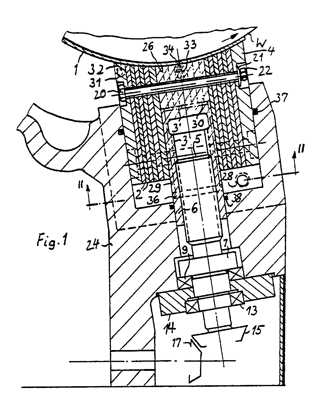
Description
Es sind bereits durch die DE-PS 663 245 Radiallager bekannt, bei denen der Tragkörper aus einzelnen, zueinander parallelen Lamellen besteht, deren Trennebenen senkrecht zu der Lagerachse verlaufen. Dabei wird durch Nuten oder zwischengelegte saugfähige Ringe eine Schmierflüssigkeit zur Lagerfläche geleitet. Hierbei sind die einzelnen Lamellen mit einer zylindrischen Innenbohrung versehen, welche in ihrer Gesamtheit die Lagerfläche ergeben. Der Grund dafür ist, für kleine, billige Lager auf einfache Weise Betriebssicherheit bei weitgehender Wartungsfreiheit zu erreichen.There are already known from DE-PS 663 245 radial bearings, in which the support body consists of individual, mutually parallel lamellae, the parting planes of which run perpendicular to the bearing axis. A lubricant is directed to the bearing surface through grooves or interposed absorbent rings. Here, the individual slats are provided with a cylindrical inner bore, which together form the bearing surface. The reason for this is that for small, cheap warehouses, operational safety can be achieved in a simple manner with little maintenance.
Es ist Aufgabe der Erfindung, eine Segmentlagerung für ein Werkstück mit zylindrischer Oberfläche zu schaffen, die für einen gewissen Lagerdurchmesserbereich einsetzbar ist, ohne daß bauliche Änderungen vorgenommen werden müssen.It is an object of the invention to provide a segment bearing for a workpiece with a cylindrical surface, which can be used for a certain bearing diameter range, without having to make structural changes.
Diese Aufgabe wird erfindungsgemäß durch die Merkmale des kennzeichnenden Teils des Patentanspruchs 1 gelöst.This object is achieved by the features of the characterizing part of
Nachfolgend wird die Erfindung anhand der in den Figuren dargestellten Beispiele erläutert, wobei
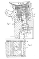
- Fig. 1 einen Querschnitt durch eine erste Ausführungsform des Lagersegments und
- Fig. 2 teilweise eine Draufsicht und Schnitt senkrecht dazu
- Fig. 1 shows a cross section through a first embodiment of the bearing segment and
- Fig. 2 partially a plan view and section perpendicular to it
Das erfindungsgemäße Lagersegment besteht aus einzelnen, zueinander parallelen Lamellen 2, die parallel zur Lagerachse bzw. Achse des Werkstücks - z.B. eine Walze W - verlaufen. Dieses Lamellenpaket wird zentral durch eine Mittelstütze 3 unterteilt. Das Lamellenpaket und die Mittelstütze 3 weisen eine Lagerfläche auf, die einem Zylindersektor entspricht und entsprechend einem mittleren Lagerradius dimensioniert ist. Die eigentliche Lagerfläche wird durch eine dünne Lagerschale 1 aus nachgiebigem Material gebildet. Es kann ein mit Weißmetall beschichtetes Stahlblech oder auch eine Schale aus sehr widerstandsfähigem, vorzugsweise auch mit guten Gleiteigenschaften für Notlauf ausgestattete Schale aus Kunststoff sein (z.B. auch aus mit Kohlenstoff- oder Aramidfaser verstärktem Kunstharz). Das Lamellenpaket wird in einem Führungsraum 8 geführt, wobei es durch seitliche Stützplatten 4 verstärkt ist. Das Lamellenpaket wird mit den Stützplatten zusammengehalten durch Spannbolzen 20, die das Lamellenpaket mittels Tellerfedern 21 und Muttern 22 zusammenspannen. Das Lamellenpaket bildet mit der Mittelstütze 3 dann eine Einheit. Jedoch ist die Mittelstütze 3 im Verhältnis zu den Lamellen in der Lagerkraftrichtung in einem gewissen Maße beweglich. Die Mittelstütze geht von einem zylindrischen Teil 6 bei 36 in einen quaderförmigen Teil über, der den Raum zwischen den Lamellen vollständig ausfüllt.The bearing segment according to the invention consists of individual, mutually
Die Mittelstütze 3 kann mittels in einer Bohrung 16 derselben angreifender Hubspindel 5 - hier über ein Kegelradgetriebe mit Kegelrädern 15 und 17 - verstellt werden. Dabei ist die Hubspindel 5 mittels einem Bund 7 und Lager 9 am Gehäuse 24 des Auflagers festgelegt. Ein weiteres Lager 13 der Hubspindel 5 ist in einer Halteplatte 14 abgestützt. Dabei ist vorzugsweise das Lager 9 ein Rollenlager und das Lager 13 ein Schrägkugellager. Das treibende Kegelzahnrad 17 sitzt auf einer Welle 19 (hier nur strichpunktiert angedeutet), welche z.B. mittels Handrad (hier nicht dargestellt) gedreht werden kann.The
Der von den Lamellen 2 und Stützplatten 4 freie Teil des Führungsraumes 8 dient als Kolbenraum und ist mit hydraulischer Druckflüssigkeit gefüllt. So wird zunächst das Werkstück - z.B. eine Walze - auf der Mittelstütze 3 gelagert und ausgerichtet, wonach dann durch Aufschaltung des hydraulischen Drucks auf das Lamellenpaket die völlige Abstützung für den Schleifvorgang - im Falle einer Schleifmaschine - bewirkt wird. Dabei ist über den Umfang des Lagerzapfens gesehen noch ein weiteres Lagersegment angeordnet, das ähnlich wie das dargestellte aufgebaut ist und zur Seitenführung des Werkstücks dient. Die Lagerschale 1 erstreckt sich dabei bis zu diesem weiteren Lagersegment, was hier nicht weiter dargestellt ist. Man kann die dargestellte Segmentlagerung für einen Durchmesserbereich von etwa 50 mm Differenz benutzen, so daß für die entsprechenden Durchmessersprünge jeweils ein neues Lamellenpaket je Lagersegment vorhanden sein müßte. Der Druckölraum ist am Lamellenpaket mittels einer Rundschnurdichtung 37 und an der Mittelstütze 3 mittels Runddichtung 38 abgedichtet. Der Führungsraum 8 ist durch seitliche Platten 39 begrenzt, die entsprechend den durch die strichpunktierten Mittellinien an ihrer Lage gekennzeichnete bzw. angedeutete Schrauben am Gehäuse 24 befestigt sind.The part of the
Es ist noch in Fig. 1 nur strichpunktiert angedeutet, daß das Lamellenpaket nicht durch eine Mittelstütze 3′ unterbrochen sein muß, sondern daß in deren Bereich sich kürzere Lamellen 26 befinden können. Mittels Aussparungen 29 und 30, die in der Mittelstütze 3′ vorgesehen sind, besteht die Möglichkeit, auch diese Lamellen mit Druckflüssigkeit zu beaufschlagen. Man kann z.B. nach Aufbringen der Druckflüssigkeit die Mittelstütze 3′ etwas zurückziehen, so daß der hydraulische Druck voll unter die kürzeren Lamellen 26 gelangen kann. Man hat hiermit eine durchgehende, noch bessere Abstützung der Lagerschale 1 bei verschiedenen Lagerdurchmessern.It is still only indicated by dash-dotted lines in Fig. 1 that the plate pack does not have to be interrupted by a central support 3 ', but that in its area there can be
Ferner könnte, zumindest für ein oberes Lagersegment, das nur verhältnismäßig geringe Lagerkräfte aufzubringen hat, die sogenannte Mittelstütze auch seitlich, also seitlich neben allen Lamellen 2 im Raum 8 angeordnet werden.Furthermore, at least for an upper bearing segment that only has to exert relatively small bearing forces, the so-called center support could also be arranged laterally, that is to say laterally, next to all the
Die Druckölzuführung für den Kolbenraum ist durch die Bohrung 28 angedeutet. Die Druckflüssigkeit für hydrostatische Druckentlastung und/oder Lagerschmierung ist jeweils durch Bohrungen 31, 32, 33 und 34 angedeutet, bei Drehrichtung des Werkstücks W (Walze) entsprechend dem dort eingetragenen Pfeil.The pressure oil supply for the piston chamber is indicated by the
Claims (9)
Priority Applications (1)
| Application Number | Priority Date | Filing Date | Title |
|---|---|---|---|
| AT89110103T ATE102304T1 (en) | 1988-06-22 | 1989-06-03 | BEARING SEGMENT FOR SEGMENT BEARING. |
Applications Claiming Priority (2)
| Application Number | Priority Date | Filing Date | Title |
|---|---|---|---|
| DE3821008 | 1988-06-22 | ||
| DE3821008A DE3821008C1 (en) | 1988-06-22 | 1988-06-22 |
Publications (3)
| Publication Number | Publication Date |
|---|---|
| EP0347635A2 true EP0347635A2 (en) | 1989-12-27 |
| EP0347635A3 EP0347635A3 (en) | 1990-12-27 |
| EP0347635B1 EP0347635B1 (en) | 1994-03-02 |
Family
ID=6356973
Family Applications (1)
| Application Number | Title | Priority Date | Filing Date |
|---|---|---|---|
| EP89110103A Expired - Lifetime EP0347635B1 (en) | 1988-06-22 | 1989-06-03 | Bearing segment for segmented bearing |
Country Status (5)
| Country | Link |
|---|---|
| US (1) | US4932794A (en) |
| EP (1) | EP0347635B1 (en) |
| AT (1) | ATE102304T1 (en) |
| DE (1) | DE3821008C1 (en) |
| ES (1) | ES2049775T3 (en) |
Cited By (1)
| Publication number | Priority date | Publication date | Assignee | Title |
|---|---|---|---|---|
| CN106272055A (en) * | 2016-11-01 | 2017-01-04 | 张钰祯 | Robot is by soft firm both sexes bistrique two dimension floating fixing device |
Family Cites Families (8)
| Publication number | Priority date | Publication date | Assignee | Title |
|---|---|---|---|---|
| DE663245C (en) * | 1935-01-08 | 1938-08-03 | Siemens Schuckertwerke Akt Ges | Bearing with a bearing body formed from discs |
| GB568704A (en) * | 1943-06-15 | 1945-04-17 | Herbert Fell | Improvements in holding or supporting devices |
| GB636339A (en) * | 1947-03-18 | 1950-04-26 | Usher Arthur Franklin Williams | Improvements in and relating to bearings and bearing surfaces |
| US3575476A (en) * | 1968-10-14 | 1971-04-20 | Gen Motors Corp | Gas bearing |
| GB2032011A (en) * | 1978-05-26 | 1980-04-30 | Capital Projects Leasing Ltd | Bearing arrangement |
| US4607964A (en) * | 1985-01-17 | 1986-08-26 | The B. F. Goodrich Company | Water lubricated bearing |
| US4749282A (en) * | 1986-05-22 | 1988-06-07 | The United States Of America As Represented By The Secretary Of The Navy | Hydrostatic supporting device |
| US4708758A (en) * | 1986-09-25 | 1987-11-24 | Morton Thiokol, Inc. | Method of making a flexible bearing |
-
1988
- 1988-06-22 DE DE3821008A patent/DE3821008C1/de not_active Expired - Fee Related
-
1989
- 1989-06-03 EP EP89110103A patent/EP0347635B1/en not_active Expired - Lifetime
- 1989-06-03 ES ES89110103T patent/ES2049775T3/en not_active Expired - Lifetime
- 1989-06-03 AT AT89110103T patent/ATE102304T1/en not_active IP Right Cessation
- 1989-06-16 US US07/367,381 patent/US4932794A/en not_active Expired - Lifetime
Cited By (2)
| Publication number | Priority date | Publication date | Assignee | Title |
|---|---|---|---|---|
| CN106272055A (en) * | 2016-11-01 | 2017-01-04 | 张钰祯 | Robot is by soft firm both sexes bistrique two dimension floating fixing device |
| CN106272055B (en) * | 2016-11-01 | 2018-06-29 | 张钰祯 | The soft firm both sexes bistrique two dimension floating fixing device of robot |
Also Published As
| Publication number | Publication date |
|---|---|
| ES2049775T3 (en) | 1994-05-01 |
| EP0347635A3 (en) | 1990-12-27 |
| DE3821008C1 (en) | 1990-01-04 |
| US4932794A (en) | 1990-06-12 |
| EP0347635B1 (en) | 1994-03-02 |
| ATE102304T1 (en) | 1994-03-15 |
Similar Documents
| Publication | Publication Date | Title |
|---|---|---|
| DE3317974C2 (en) | ||
| DE8809823U1 (en) | Rolling tool | |
| DE2943644A1 (en) | ROLLER ARRANGEMENT FOR PRESSURE TREATING TRACKS | |
| DE3005147C2 (en) | Backlash-free precision drive for a rotating or a longitudinally displaceable part | |
| EP0619154B1 (en) | Straightening apparatus for wire, multiple wire or tubular products | |
| DE1243965B (en) | Roller for the pressure treatment of material webs such as paper and textile webs | |
| DE102012222172A1 (en) | Axial piston machine with conical piston | |
| DE1525213A1 (en) | Ball bearings and method and device for their manufacture | |
| DE2001672B2 (en) | Track roller | |
| EP0347635A2 (en) | Bearing segment for segmented bearing | |
| EP0144786A1 (en) | Separation device | |
| DE2831142C2 (en) | Deflection adjustment roller | |
| DE1602908A1 (en) | Drilling machine in the manner of a radial drilling machine | |
| DE3817973A1 (en) | Smoothing device of an application mechanism | |
| CH623894A5 (en) | Hydraulic screw machine | |
| DE463891C (en) | Device for mounting the rolls in rolling mills | |
| DE4011364C2 (en) | ||
| DE102005016318A1 (en) | Process for grinding aqueous suspended paper or pulp fibers and grinding device for its implementation | |
| DE3621979C2 (en) | ||
| DE3146021C2 (en) | Weighing device | |
| CH658496A5 (en) | HOSE CRUSH PUMP. | |
| DE2048164A1 (en) | Axial piston machine | |
| AT167045B (en) | Axial piston gear with swash plate drive | |
| AT242517B (en) | Liquid pump or motor | |
| DE2953848C1 (en) | Overload protection for hoe or winch |
Legal Events
| Date | Code | Title | Description |
|---|---|---|---|
| PUAI | Public reference made under article 153(3) epc to a published international application that has entered the european phase |
Free format text: ORIGINAL CODE: 0009012 |
|
| AK | Designated contracting states |
Kind code of ref document: A2 Designated state(s): AT CH ES FR GB IT LI NL SE |
|
| PUAL | Search report despatched |
Free format text: ORIGINAL CODE: 0009013 |
|
| AK | Designated contracting states |
Kind code of ref document: A3 Designated state(s): AT CH ES FR GB IT LI NL SE |
|
| 17P | Request for examination filed |
Effective date: 19901222 |
|
| 17Q | First examination report despatched |
Effective date: 19920622 |
|
| GRAA | (expected) grant |
Free format text: ORIGINAL CODE: 0009210 |
|
| AK | Designated contracting states |
Kind code of ref document: B1 Designated state(s): AT CH ES FR GB IT LI NL SE |
|
| REF | Corresponds to: |
Ref document number: 102304 Country of ref document: AT Date of ref document: 19940315 Kind code of ref document: T |
|
| GBT | Gb: translation of ep patent filed (gb section 77(6)(a)/1977) |
Effective date: 19940323 |
|
| REG | Reference to a national code |
Ref country code: ES Ref legal event code: FG2A Ref document number: 2049775 Country of ref document: ES Kind code of ref document: T3 |
|
| ITF | It: translation for a ep patent filed | ||
| ET | Fr: translation filed | ||
| PLBE | No opposition filed within time limit |
Free format text: ORIGINAL CODE: 0009261 |
|
| STAA | Information on the status of an ep patent application or granted ep patent |
Free format text: STATUS: NO OPPOSITION FILED WITHIN TIME LIMIT |
|
| EAL | Se: european patent in force in sweden |
Ref document number: 89110103.2 |
|
| 26N | No opposition filed | ||
| REG | Reference to a national code |
Ref country code: GB Ref legal event code: IF02 |
|
| PGFP | Annual fee paid to national office [announced via postgrant information from national office to epo] |
Ref country code: GB Payment date: 20050525 Year of fee payment: 17 |
|
| PGFP | Annual fee paid to national office [announced via postgrant information from national office to epo] |
Ref country code: FR Payment date: 20050610 Year of fee payment: 17 |
|
| PGFP | Annual fee paid to national office [announced via postgrant information from national office to epo] |
Ref country code: SE Payment date: 20050614 Year of fee payment: 17 Ref country code: CH Payment date: 20050614 Year of fee payment: 17 |
|
| PGFP | Annual fee paid to national office [announced via postgrant information from national office to epo] |
Ref country code: NL Payment date: 20050615 Year of fee payment: 17 Ref country code: ES Payment date: 20050615 Year of fee payment: 17 Ref country code: AT Payment date: 20050615 Year of fee payment: 17 |
|
| PG25 | Lapsed in a contracting state [announced via postgrant information from national office to epo] |
Ref country code: GB Free format text: LAPSE BECAUSE OF NON-PAYMENT OF DUE FEES Effective date: 20060603 Ref country code: AT Free format text: LAPSE BECAUSE OF NON-PAYMENT OF DUE FEES Effective date: 20060603 |
|
| PG25 | Lapsed in a contracting state [announced via postgrant information from national office to epo] |
Ref country code: SE Free format text: LAPSE BECAUSE OF NON-PAYMENT OF DUE FEES Effective date: 20060604 |
|
| PG25 | Lapsed in a contracting state [announced via postgrant information from national office to epo] |
Ref country code: ES Free format text: LAPSE BECAUSE OF NON-PAYMENT OF DUE FEES Effective date: 20060605 |
|
| PG25 | Lapsed in a contracting state [announced via postgrant information from national office to epo] |
Ref country code: LI Free format text: LAPSE BECAUSE OF NON-PAYMENT OF DUE FEES Effective date: 20060630 Ref country code: CH Free format text: LAPSE BECAUSE OF NON-PAYMENT OF DUE FEES Effective date: 20060630 |
|
| PGFP | Annual fee paid to national office [announced via postgrant information from national office to epo] |
Ref country code: IT Payment date: 20060630 Year of fee payment: 18 |
|
| PG25 | Lapsed in a contracting state [announced via postgrant information from national office to epo] |
Ref country code: NL Free format text: LAPSE BECAUSE OF NON-PAYMENT OF DUE FEES Effective date: 20070101 |
|
| REG | Reference to a national code |
Ref country code: CH Ref legal event code: PL |
|
| EUG | Se: european patent has lapsed | ||
| GBPC | Gb: european patent ceased through non-payment of renewal fee |
Effective date: 20060603 |
|
| NLV4 | Nl: lapsed or anulled due to non-payment of the annual fee |
Effective date: 20070101 |
|
| REG | Reference to a national code |
Ref country code: FR Ref legal event code: ST Effective date: 20070228 |
|
| REG | Reference to a national code |
Ref country code: ES Ref legal event code: FD2A Effective date: 20060605 |
|
| PG25 | Lapsed in a contracting state [announced via postgrant information from national office to epo] |
Ref country code: FR Free format text: LAPSE BECAUSE OF NON-PAYMENT OF DUE FEES Effective date: 20060630 |
|
| PG25 | Lapsed in a contracting state [announced via postgrant information from national office to epo] |
Ref country code: IT Free format text: LAPSE BECAUSE OF NON-PAYMENT OF DUE FEES Effective date: 20070603 |