EP0347575A2 - Pneumatic vehicle tyres - Google Patents
Pneumatic vehicle tyres Download PDFInfo
- Publication number
- EP0347575A2 EP0347575A2 EP89108554A EP89108554A EP0347575A2 EP 0347575 A2 EP0347575 A2 EP 0347575A2 EP 89108554 A EP89108554 A EP 89108554A EP 89108554 A EP89108554 A EP 89108554A EP 0347575 A2 EP0347575 A2 EP 0347575A2
- Authority
- EP
- European Patent Office
- Prior art keywords
- profile
- rib
- ribs
- circumferential
- circumferential direction
- Prior art date
- Legal status (The legal status is an assumption and is not a legal conclusion. Google has not performed a legal analysis and makes no representation as to the accuracy of the status listed.)
- Ceased
Links
Images
Classifications
-
- B—PERFORMING OPERATIONS; TRANSPORTING
- B60—VEHICLES IN GENERAL
- B60C—VEHICLE TYRES; TYRE INFLATION; TYRE CHANGING; CONNECTING VALVES TO INFLATABLE ELASTIC BODIES IN GENERAL; DEVICES OR ARRANGEMENTS RELATED TO TYRES
- B60C11/00—Tyre tread bands; Tread patterns; Anti-skid inserts
- B60C11/03—Tread patterns
- B60C11/11—Tread patterns in which the raised area of the pattern consists only of isolated elements, e.g. blocks
-
- B—PERFORMING OPERATIONS; TRANSPORTING
- B60—VEHICLES IN GENERAL
- B60C—VEHICLE TYRES; TYRE INFLATION; TYRE CHANGING; CONNECTING VALVES TO INFLATABLE ELASTIC BODIES IN GENERAL; DEVICES OR ARRANGEMENTS RELATED TO TYRES
- B60C11/00—Tyre tread bands; Tread patterns; Anti-skid inserts
- B60C11/03—Tread patterns
- B60C11/12—Tread patterns characterised by the use of narrow slits or incisions, e.g. sipes
- B60C11/1204—Tread patterns characterised by the use of narrow slits or incisions, e.g. sipes with special shape of the sipe
- B60C2011/1213—Tread patterns characterised by the use of narrow slits or incisions, e.g. sipes with special shape of the sipe sinusoidal or zigzag at the tread surface
-
- Y—GENERAL TAGGING OF NEW TECHNOLOGICAL DEVELOPMENTS; GENERAL TAGGING OF CROSS-SECTIONAL TECHNOLOGIES SPANNING OVER SEVERAL SECTIONS OF THE IPC; TECHNICAL SUBJECTS COVERED BY FORMER USPC CROSS-REFERENCE ART COLLECTIONS [XRACs] AND DIGESTS
- Y10—TECHNICAL SUBJECTS COVERED BY FORMER USPC
- Y10S—TECHNICAL SUBJECTS COVERED BY FORMER USPC CROSS-REFERENCE ART COLLECTIONS [XRACs] AND DIGESTS
- Y10S152/00—Resilient tires and wheels
- Y10S152/03—Slits in threads
Definitions
- the invention relates to a pneumatic vehicle tire according to the preamble of claim 1.
- a pneumatic vehicle tire with a tread pattern which consists of circumferential ribs which are separated from one another by circumferential grooves and which are divided by fine incisions oriented obliquely to the circumferential direction
- the object is achieved in that the rib profile members formed by stepped fine incisions have a rune-shaped contact surface and are arranged in the circumferential direction in such a way that their nose-shaped link section protrudes alternately on the right and left in the essentially straight circumferential channels, a recess being arranged opposite a projecting link section .
- slender profile formed by the circumferential division of sixty-fourths, with strong transverse lamination. It preferably consists of seven circumferential ribs with a footprint portion that is essentially equal to the negative portion of the grooves.
- the cross-lamination improves the wet-skid resistance, the oblique orientation of the fine incisions changing in the direction from rib to rib.
- the ribs and grooves receive an offset, the good traction, due to the nose-shaped attachment of the rib member guaranteed.
- the invention is explained using an exemplary embodiment.
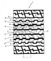
- the drawing figure shows a top view of the tread pattern 1 of a pneumatic vehicle tire.
- the profile consists of a circumferential rib 2 arranged in the center of the tread, the circumferential ribs 3 and 4 arranged adjacent to the right and left, separated by circumferential grooves 10, and the circumferential ribs 5 and 6 arranged in the tire shoulders, each of which by circumferential grooves 11 from the circumferential ribs passing into the tire shoulder 7 and 8 are separated.
- the profile ribs essentially consist of rune-shaped rib members formed by the stepped fine incisions 12, 13. In the middle rib 2 there are two rib members 14, 15. The rune-like contact area is each extended by a nose-shaped link section 16, 17. These rib members are adjacent in the circumferential direction, wherein they abut each other in the 180 o twisted arrangement and so a rib having alternating right and left offset present form.
- the rib side edges running parallel to the circumferential direction are designated by 20, 21.
- the circumference division t is 1/64.
- the circumferential ribs 3, 4 consist of the rib members 24, 25, the rune-shaped contact surface of which is expanded on the rib member 24 by a nose-shaped link section 26. These are in and against the circumferential direction adjacent to the rib members 25, these being present in at 180 ° twisted arrangement.
- the rib side edges that run parallel to the circumferential direction are designated by 22, 23 and the corresponding rib side edges of the links 25 are designated by 29.
- the circumferential ribs 2 and 3 and 4 are arranged on the basis of their rib links formed by the strong transverse lamination of the fine incisions 12, 13, which are arranged equally obliquely but in opposite directions, such that the nose-shaped link set 16, 17 has a cutout on the adjacent rib opposite. These sections are designated 30, 31.
- the circumferential ribs 5, 6 consist of the rib members 34, 35. Their rune-shaped contact surface is each expanded by a nose-shaped link section 36, 37. A cutout on the adjacent rib lies opposite each of these link sections. These sections are labeled 38, 39.
- the ribs 7, 8 on the shoulder side are less frequently divided by fine incisions for reasons of arrangement in the tire shoulder.
- they form the same pattern as the other rib members and, through their rib members 40, supplement the offset groove 11, which separates them from the rib 5 or 6.
- the decorative elements 42, 43 are separated from the rib profile of the shoulder rib 7, 8 by a decoupling groove 9.
Abstract
Description
Die Erfindung betrifft einen Fahrzeugluftreifen nach dem Oberbegriff des Anspruchs 1.The invention relates to a pneumatic vehicle tire according to the preamble of claim 1.
Bei einem Fahrzeugluftreifen mit einem Laufflächenprofil, das aus Umfangsrippen besteht, die durch Umfangsrillen voneinander getrennt sind und die durch schräg zur Umfangsrichtung orientierte Feineinschnitte gegliedert sind, ist es Aufgabe der Erfindung, die durch die Feineinschnitte aufgeteilten Profilrippen in den Eigenschaften Naßrutschfestigkeit, Traktion, gleichmäßiger Abrieb und Laufruhe gegenüber Reifen mit einem gattungsgemäßen Laufflächenprofil zu verbessern.In a pneumatic vehicle tire with a tread pattern, which consists of circumferential ribs which are separated from one another by circumferential grooves and which are divided by fine incisions oriented obliquely to the circumferential direction, it is the object of the invention to provide the profile ribs divided by the fine incisions in the properties of wet slip resistance, traction and uniform abrasion and to improve smoothness compared to tires with a generic tread pattern.
Erfindungsgemäß wird die Aufgabe dadurch gelöst, daß die durch gestufte Feineinschnitte gebildeten Rippenprofilglieder eine runenförmige Aufstandsfläche aufweisen und in Umfangsrichtung derart angeordnet sind, daß deren nasenförmiger Gliederabschnitt abwechselnd rechts und links in den im wesentlichen geraden Umfangskanälen vorsteht, wobei einem vorspringenden Gliederabschnitt eine Ausnehmung gegenüber angeordnet ist.According to the invention, the object is achieved in that the rib profile members formed by stepped fine incisions have a rune-shaped contact surface and are arranged in the circumferential direction in such a way that their nose-shaped link section protrudes alternately on the right and left in the essentially straight circumferential channels, a recess being arranged opposite a projecting link section .
Es liegt ein feingliedriges, durch die Umfangsteilung von Vierundsechzigstel gebildetes Profil mit starker Querlamellierung vor. Bevorzugt besteht es aus sieben Umfangsrippen mit einem Aufstandsflächenanteil, der im wesentlichen gleich dem Negativanteil der Rillen ist. Durch die Querlamellierung wird die Naßrutschfestigkeit verbessert, wobei die Schrägorientierung der Feineinschnitte in der Richtung von Rippe zu Rippe wechselt.There is a slender profile, formed by the circumferential division of sixty-fourths, with strong transverse lamination. It preferably consists of seven circumferential ribs with a footprint portion that is essentially equal to the negative portion of the grooves. The cross-lamination improves the wet-skid resistance, the oblique orientation of the fine incisions changing in the direction from rib to rib.
Durch den nasenförmigen Ansatz des Rippengliedes erhalten die Rippen und Rillen einen Versatz, der gute Traktion gewährleistet. Die Form der Rippenglieder und deren durch die Feineinschnitte gegliederte Anordnung ergibt Umfangsrippen, die gleichmäßigen Abrieb und geringes Reifengeräusch gewährleisten.The ribs and grooves receive an offset, the good traction, due to the nose-shaped attachment of the rib member guaranteed. The shape of the rib members and their arrangement, which is divided by the fine incisions, results in circumferential ribs which ensure uniform abrasion and low tire noise.
An Hand eines Ausführungsbeispiels ist die Erfindung erläutert. Die Zeichenfigur zeigt eine Aufsicht auf das Laufflächenprofil 1 eines Fahrzeugluftreifens.The invention is explained using an exemplary embodiment. The drawing figure shows a top view of the tread pattern 1 of a pneumatic vehicle tire.
Das Profil besteht aus einer in der Laufflächenmitte angeordneten Umfangsrippe 2, den rechts und links benachbart angeordneten, durch Umfangsrillen 10 getrennten Umfangsrippen 3 und 4 und den in den Reifenschultern angeordneten Umfangsrippen 5 und 6, die jeweils durch Umfangsrillen 11 von den in die Reifenschulter übergehenden Umfangsrippen 7 und 8 getrennt sind.The profile consists of a circumferential rib 2 arranged in the center of the tread, the
Die Profilrippen bestehen im wesentlichen aus durch die gestuften Feineinschnitte 12, 13 gebildeten runenförmigen Rippenglieder. In der Mittenrippe 2 sind zwei Rippenglieder 14, 15 vorhanden. Die runenförmige Aufstandsfläche ist jeweils durch einen nasenförmigen Gliedabschnitt 16, 17 erweitert. Diese Rippenglieder sind in Umfangsrichtung benachbart, wobei sie in der um 180o gedrehten Anordnung aneinanderliegen und so eine Rippe mit wechselnd rechts und links vorliegendem Versatz bilden.The profile ribs essentially consist of rune-shaped rib members formed by the stepped
Die parallel zur Umfangsrichtung verlaufenden Rippenseitenkanten sind mit 20, 21 bezeichnet. Die Umfangsteilung t beträgt 1/64.The rib side edges running parallel to the circumferential direction are designated by 20, 21. The circumference division t is 1/64.
Die Umfangsrippen 3, 4 bestehen aus den Rippengliedern 24, 25. Deren runenförmige Aufstandsfläche ist jeweils an dem Rippenglied 24 durch einen nasenförmigen Gliedabschnitt 26 erweitert. Diesem sind in und entgegen der Umfangsrichtung die Rippenglieder 25 benachbart, wobei diese in um 180o gedrehter Anordnung vorliegen.The
Die parallel zur Umfangsrichtung verlaufenden Rippenseitenkanten sind mit 22, 23 bezeichnet und die entsprechend verlaufenden Rippenseitenkanten der Glieder 25 sind mit 29 bezeichnet.The rib side edges that run parallel to the circumferential direction are designated by 22, 23 and the corresponding rib side edges of the
Die Umfangsrippen 2 und 3 bzw. 4 sind auf Grund ihrer durch die starke Querlamellierung der Feineinschnitte 12, 13, die gleich schräg, jedoch entgegengerichtet angeordnet sind, ausgebildeten Rippenglieder so angeordnet, daß jeweils dem nasenförmigen Gliedersatz 16, 17 ein Ausschnitt an der benachbarten Rippe gegenüberliegt. Diese Ausschnitte sind mit 30, 31 bezeichnet.The
Die Umfangsrippen 5, 6 bestehen aus den Rippengliedern 34, 35. Deren runenförmige Aufstandsfläche ist jeweils durch einen nasenförmigen Gliedabschnitt 36, 37 erweitert. Diesen Gliedabschnitten liegt jeweils ein Ausschnitt an der benachbarten Rippe gegenüber. Diese Ausschnitte sind mit 38, 39 bezeichnet.The
Die schulterseitig äußeren Rippen 7, 8 sind aus Gründen der Anordnung in der Reifenschulter weniger häufig durch Feineinschnitte gegliedert. In der Grundform bilden sie das gleiche Muster wie die übrigen Rippenglieder und ergänzen durch ihre Rippenglieder 40 die Versatzrille 11, die sie von der Rippe 5 bzw. 6 trennt.The
Die Dekorelemente 42, 43 sind von dem Rippenprofil der Schulterrippe 7, 8 durch eine Entkoppelungsrille 9 getrennt.The
Claims (4)
Applications Claiming Priority (2)
| Application Number | Priority Date | Filing Date | Title |
|---|---|---|---|
| DE8807996U | 1988-06-22 | ||
| DE8807996U DE8807996U1 (en) | 1988-06-22 | 1988-06-22 |
Publications (2)
| Publication Number | Publication Date |
|---|---|
| EP0347575A2 true EP0347575A2 (en) | 1989-12-27 |
| EP0347575A3 EP0347575A3 (en) | 1990-05-02 |
Family
ID=6825227
Family Applications (1)
| Application Number | Title | Priority Date | Filing Date |
|---|---|---|---|
| EP89108554A Ceased EP0347575A3 (en) | 1988-06-22 | 1989-05-12 | Pneumatic vehicle tyres |
Country Status (4)
| Country | Link |
|---|---|
| US (1) | US4982774A (en) |
| EP (1) | EP0347575A3 (en) |
| JP (1) | JPH0234407A (en) |
| DE (1) | DE8807996U1 (en) |
Cited By (2)
| Publication number | Priority date | Publication date | Assignee | Title |
|---|---|---|---|---|
| EP0434967A3 (en) * | 1989-12-29 | 1991-12-11 | Continental Ag | Tread pattern for vehicle tires |
| EP0613794A1 (en) * | 1993-03-02 | 1994-09-07 | PIRELLI REIFENWERKE GmbH | Winter tyre tread |
Families Citing this family (5)
| Publication number | Priority date | Publication date | Assignee | Title |
|---|---|---|---|---|
| AT394337B (en) * | 1989-04-13 | 1992-03-10 | Semperit Ag | RADIAL TIRES FOR TRUCKS |
| JP2795378B2 (en) * | 1989-10-02 | 1998-09-10 | 住友ゴム工業 株式会社 | Pneumatic all season tires |
| USD418785S (en) * | 1999-02-05 | 2000-01-11 | The Goodyear Tire & Rubber Company | Tire tread |
| FR2961744B1 (en) * | 2010-06-29 | 2012-08-03 | Michelin Soc Tech | BEARING BAND WITH REDUCED DRIVE NOISE |
| JP5320428B2 (en) * | 2011-04-12 | 2013-10-23 | 住友ゴム工業株式会社 | Pneumatic tire |
Citations (3)
| Publication number | Priority date | Publication date | Assignee | Title |
|---|---|---|---|---|
| DE2127470A1 (en) * | 1971-06-03 | 1972-12-14 | Continental Gummi-Werke Ag, 3000 Hannover | Tread profile for pneumatic vehicle tires |
| FR2278508A1 (en) * | 1974-07-18 | 1976-02-13 | Mirtain Henri | VEHICLE WHEEL PNEUMATIC BANDAGE WRAP |
| FR2526722A1 (en) * | 1982-05-12 | 1983-11-18 | Bridgestone Tire Co Ltd | TREAD SCULPTURE FOR A RADIAL CARCASS PNEUMATIC TIRE FOR HEAVY WEIGHT |
Family Cites Families (3)
| Publication number | Priority date | Publication date | Assignee | Title |
|---|---|---|---|---|
| IT1176226B (en) * | 1984-06-01 | 1987-08-18 | Pirelli | IMPROVEMENTS TO THE TIRES OF TIRES FOR VEHICLES |
| DE3445041C2 (en) * | 1984-12-11 | 1996-05-23 | Continental Ag | Tread for pneumatic vehicle tires |
| US4926919A (en) * | 1988-11-14 | 1990-05-22 | The Goodyear Tire & Rubber Company | Vehicle tire with rib type tread pattern having sipes across the ribs |
-
1988
- 1988-06-22 DE DE8807996U patent/DE8807996U1/de not_active Expired
-
1989
- 1989-05-12 EP EP89108554A patent/EP0347575A3/en not_active Ceased
- 1989-06-13 JP JP1148538A patent/JPH0234407A/en active Pending
- 1989-06-22 US US07/369,774 patent/US4982774A/en not_active Expired - Fee Related
Patent Citations (3)
| Publication number | Priority date | Publication date | Assignee | Title |
|---|---|---|---|---|
| DE2127470A1 (en) * | 1971-06-03 | 1972-12-14 | Continental Gummi-Werke Ag, 3000 Hannover | Tread profile for pneumatic vehicle tires |
| FR2278508A1 (en) * | 1974-07-18 | 1976-02-13 | Mirtain Henri | VEHICLE WHEEL PNEUMATIC BANDAGE WRAP |
| FR2526722A1 (en) * | 1982-05-12 | 1983-11-18 | Bridgestone Tire Co Ltd | TREAD SCULPTURE FOR A RADIAL CARCASS PNEUMATIC TIRE FOR HEAVY WEIGHT |
Non-Patent Citations (1)
| Title |
|---|
| GUMMIBEREIFUNG, Band 61, Nr. 4, April 1985, Seite 48, Bielefeld, DE; Fulda Diadem Stahl * |
Cited By (2)
| Publication number | Priority date | Publication date | Assignee | Title |
|---|---|---|---|---|
| EP0434967A3 (en) * | 1989-12-29 | 1991-12-11 | Continental Ag | Tread pattern for vehicle tires |
| EP0613794A1 (en) * | 1993-03-02 | 1994-09-07 | PIRELLI REIFENWERKE GmbH | Winter tyre tread |
Also Published As
| Publication number | Publication date |
|---|---|
| DE8807996U1 (en) | 1988-08-25 |
| EP0347575A3 (en) | 1990-05-02 |
| US4982774A (en) | 1991-01-08 |
| JPH0234407A (en) | 1990-02-05 |
Similar Documents
| Publication | Publication Date | Title |
|---|---|---|
| DE3314886C2 (en) | ||
| DE602005004086T2 (en) | tire | |
| DE2532752C2 (en) | tire | |
| DE2710825C2 (en) | ||
| EP2067636B1 (en) | Pneumatic tyres for a vehicle | |
| DE10214913A1 (en) | Pneumatic tire, has tread made up of blocks divided by circumferential and transverse grooves, each block having transverse, zigzag grooves dividing it internally into tetrahedral projections and recesses | |
| DE3723368A1 (en) | RUNNING PROFILE ON AIR TIRES | |
| DE3410806A1 (en) | RADIAL TIRES FOR HIGH LOADS | |
| DE1680404C3 (en) | tire | |
| EP0075760B1 (en) | Pneumatic tyre for vehicles | |
| DE1291238B (en) | Pneumatic vehicle tires with an asymmetrical tread pattern | |
| DE69921586T2 (en) | tire | |
| DE3907074A1 (en) | VEHICLE TIRES | |
| DE3712155A1 (en) | Radial tyre | |
| EP0347575A2 (en) | Pneumatic vehicle tyres | |
| DE3044508A1 (en) | PNEUMATIC TIRE | |
| EP2666648A1 (en) | Pneumatic tyres for a vehicle | |
| EP2785537B1 (en) | Pneumatic vehicle tyre | |
| AT394684B (en) | Tyre cap profile for a pneumatic vehicle tyre | |
| DE60122975T2 (en) | tire | |
| EP0715972B1 (en) | Vehicle tyre | |
| DE3118407A1 (en) | Pneumatic vehicle tyre | |
| EP3045326B1 (en) | Pneumatic tyres for a vehicle | |
| DE4326036A1 (en) | Tread for pneumatic vehicle tires | |
| EP0082293A2 (en) | Tread pattern for vehicles tyres, in particular for spare tyres |
Legal Events
| Date | Code | Title | Description |
|---|---|---|---|
| PUAI | Public reference made under article 153(3) epc to a published international application that has entered the european phase |
Free format text: ORIGINAL CODE: 0009012 |
|
| AK | Designated contracting states |
Kind code of ref document: A2 Designated state(s): AT BE CH DE ES FR GB GR IT LI LU NL SE |
|
| PUAL | Search report despatched |
Free format text: ORIGINAL CODE: 0009013 |
|
| AK | Designated contracting states |
Kind code of ref document: A3 Designated state(s): AT BE CH DE ES FR GB GR IT LI LU NL SE |
|
| 17P | Request for examination filed |
Effective date: 19900321 |
|
| 17Q | First examination report despatched |
Effective date: 19910604 |
|
| STAA | Information on the status of an ep patent application or granted ep patent |
Free format text: STATUS: THE APPLICATION HAS BEEN REFUSED |
|
| 18R | Application refused |
Effective date: 19911128 |