EP0347562A2 - Safety valve - Google Patents
Safety valve Download PDFInfo
- Publication number
- EP0347562A2 EP0347562A2 EP89107714A EP89107714A EP0347562A2 EP 0347562 A2 EP0347562 A2 EP 0347562A2 EP 89107714 A EP89107714 A EP 89107714A EP 89107714 A EP89107714 A EP 89107714A EP 0347562 A2 EP0347562 A2 EP 0347562A2
- Authority
- EP
- European Patent Office
- Prior art keywords
- connection
- valve
- working
- channel
- tank
- Prior art date
- Legal status (The legal status is an assumption and is not a legal conclusion. Google has not performed a legal analysis and makes no representation as to the accuracy of the status listed.)
- Withdrawn
Links
Images

Classifications
-
- F—MECHANICAL ENGINEERING; LIGHTING; HEATING; WEAPONS; BLASTING
- F15—FLUID-PRESSURE ACTUATORS; HYDRAULICS OR PNEUMATICS IN GENERAL
- F15B—SYSTEMS ACTING BY MEANS OF FLUIDS IN GENERAL; FLUID-PRESSURE ACTUATORS, e.g. SERVOMOTORS; DETAILS OF FLUID-PRESSURE SYSTEMS, NOT OTHERWISE PROVIDED FOR
- F15B20/00—Safety arrangements for fluid actuator systems; Applications of safety devices in fluid actuator systems; Emergency measures for fluid actuator systems
- F15B20/001—Double valve requiring the use of both hands simultaneously
-
- Y—GENERAL TAGGING OF NEW TECHNOLOGICAL DEVELOPMENTS; GENERAL TAGGING OF CROSS-SECTIONAL TECHNOLOGIES SPANNING OVER SEVERAL SECTIONS OF THE IPC; TECHNICAL SUBJECTS COVERED BY FORMER USPC CROSS-REFERENCE ART COLLECTIONS [XRACs] AND DIGESTS
- Y10—TECHNICAL SUBJECTS COVERED BY FORMER USPC
- Y10T—TECHNICAL SUBJECTS COVERED BY FORMER US CLASSIFICATION
- Y10T137/00—Fluid handling
- Y10T137/8593—Systems
- Y10T137/87169—Supply and exhaust
- Y10T137/87193—Pilot-actuated
- Y10T137/87209—Electric
-
- Y—GENERAL TAGGING OF NEW TECHNOLOGICAL DEVELOPMENTS; GENERAL TAGGING OF CROSS-SECTIONAL TECHNOLOGIES SPANNING OVER SEVERAL SECTIONS OF THE IPC; TECHNICAL SUBJECTS COVERED BY FORMER USPC CROSS-REFERENCE ART COLLECTIONS [XRACs] AND DIGESTS
- Y10—TECHNICAL SUBJECTS COVERED BY FORMER USPC
- Y10T—TECHNICAL SUBJECTS COVERED BY FORMER US CLASSIFICATION
- Y10T137/00—Fluid handling
- Y10T137/8593—Systems
- Y10T137/87169—Supply and exhaust
- Y10T137/87217—Motor
- Y10T137/87225—Fluid motor
Definitions
- the invention relates to a hydraulically actuated 5/2-way safety valve, consisting of a valve housing with two valve bodies which can be moved in opposite directions in a bore in the housing, two e.g. Electromagnetically actuated pilot valves, a pump connection, two working connections and two tank connections, the valve bodies each having a working piston, which can be acted upon by the pressure medium via control channels and the pilot valves, and control pistons connected to the working piston, which have the connections between the pump connection, the working connections and control the tank connection.
- Safety valves of the aforementioned type are e.g. used to operate the brake and clutch of a mechanical press.
- a valve consists of two directional control valves, so that if one valve fails, the braking process is still guaranteed.
- the invention is based on the object of developing a safety valve of the type mentioned at the outset so that automatic monitoring of the valve is made possible without the use of special additional monitoring elements.
- the speed and pressure build-up at the consumer e.g. be controllable on a differential cylinder.
- each of the two valve bodies is formed from three axially spaced control pistons, through which, in conjunction with corresponding control edges in the housing in the basic position of the valve, the pump port P with the working port B and the working port A with the Tank connection R is connectable; through which, in the switching position of the valve, the pump connection P can be connected to the working connection A and the working connection B to the tank connection S; and by which finally, in the event of a malfunction, the pump connection P can be connected to the working connection B and the working connection A can be connected to the tank connection R.
- the safety valve is preferably coupled to a proportional three-way pressure reducing valve, one side of which is permanently connected to the tank connection S of the safety valve and the other side of which, depending on its switching position, can be connected to the connection R or the pump connection P of the safety valve.
- a central bore 16 is formed in the housing, in which two valve bodies 18, 20 can be moved axially in opposite directions to one another.
- Each valve body is provided with a working piston 22, which has a blind bore, not designated in any more detail, in which a compression spring 24 is arranged and the two compression springs 24 seek to press the two valve bodies 18, 20 axially towards one another, in the basic position shown in FIG. 1 , in which the two pilot valves 12, 14 are not energized, the two The valve bodies 18, 20 abut one another with their end faces.
- the valve body 18 is provided with control pistons 26, 28, 30 and the valve body 20 is provided with control pistons 32, 34, 36.
- each of the working pistons 22 has a transverse bore 38, which connects the respective blind bore of the working piston to the space outside the working piston and opens into an annular groove 120 formed on the circumference of the respective working piston.
- the central bore 16 is provided with annular channels 78, 80, 82, 84 86, 88, 90, 92, 94, 96, and pockets 74, 76, 98 and 100, which are arranged at axial distances and lie in planes transverse to their axis.
- the ring channels and pockets together with the housing form control edges with which the aforementioned control pistons interact.
- the safety valve has a pump connection P, working connections A and B and tank connections R and S.
- a channel 40 runs from the pump connection P to a ring channel 122 of the central bore
- a channel 42 runs from the working connection A to the ring channel 94
- a channel 44 runs from the working connection B to the ring channel 90
- a channel 46 runs from the tank connection R to the ring channel 78
- a channel 48 extends from the tank connection S to an annular channel 124 of the central bore 16.
- branch channel 50 which opens into the ring channel 96 and two branch channels 52 branch off from the channel 40, one of which opens into the pocket 76 via an annular groove of the left working piston 22, while the other via an annular groove of the right Working piston 22 opens into the pocket 98.
- the ring channels 86 and 92 are connected by a connecting channel 54
- the ring channels 84 and 90 are connected by a connecting channel 56
- the ring channels 82 and 88 are connected by a connecting channel 58
- the ring channels 80, 94 are connected by a connecting channel 60 .
- the pilot valve 12 is provided with a piston 102 which can be moved axially back and forth in a bore in the valve housing. It is held in the basic position shown in FIG. 1 by compression springs 108, which are arranged in spring chambers 110, when the electromagnet 106 is not energized.
- the spring chambers 110 are constantly connected to one another via a connecting channel 112.
- the central bore is provided with annular channels 126, 128, 130 formed at axial intervals.
- the pilot valve 14 has a piston 104 which can be moved back and forth in an axial bore and which is held in the basic position shown in FIG. 1 by compression springs 114 which are arranged in spring chambers 116 when the electromagnet 106 is not excited.
- the two spring chambers 116 are constantly connected to one another via a connecting channel 118.
- the central bore is provided with annular channels 132, 134 and 136 formed at axial intervals.
- Control channels 62, 64, 66 and 68, 70, 72 are also formed in the housing of the safety valve, the control channel 62 leading from the pocket 74 to the ring channel 128 of the pilot valve 12; the control channel 64 leads from the pocket 76 to the ring channel 132 of the pilot valve 14; the control channel 66 leads from the ring channel 78 to the ring channel 126 of the pilot valve 12.
- the control channel 68 leads from the pocket 100 to the ring channel 134 of the pilot valve 14; the control channel 70 leads from pocket 98 to the ring channel 130 of the pilot valve 12 and the control channel 72 leads from the ring channel 96 to the ring channel 136 of the pilot valve 14.
- the safety valve according to the invention works as follows. 1 shows the basic position in which the two electromagnets 106 of the pilot valves 12, 14 are not energized.
- the left working piston 22 is supplied with the pump pressure by the inlet P via the right branch channel 52, the control channel 70, the pilot valve 12 and the control channel 62;
- the right working piston 22 is acted upon by the pump pressure via the left branch channel 52, the control channel 64, the pilot valve 14 and the control channel 68.
- these pressures cancel each other out and the two valve bodies 18, 20 are pressed together by their springs 24 until they meet with their end faces and the one shown in FIG.
- the pump connection P is connected to the channel 44 and thus to the working connection B via the channel 40, the ring channel 122, the ring channel 84, the connecting channel 56 and the ring channel 90.
- the working connection A is connected via the channel 42, the ring channel 94, the ring channel 96 and the branch channel 50 to the channel 46 and thus to the tank connection R (also also via 60, 80, 78 and 46).
- the pilot valves 12 and 14 are activated, their magnets are energized and their pistons 102, 104 are switched to their switching position.
- the left-hand working piston 22 is connected via its transverse bore 38, the annular groove 120, the pocket 74, the control channel 62, the pilot valve 12, the control channel 66 and the annular groove 78 to the channel 46 and thus to the tank connection R.
- the right-hand working piston 22 is likewise connected to the tank connection R via its transverse bore 38, the annular groove 120, the pocket 100, the control channel 68, the pilot valve 14, the control channel 72, the annular channel 96 and the branch channel 50.
- the pump connection P is connected to the channel 42 and thus to the working connection A via the channel 40, the ring channels 122, 86, the connecting channel 54 and the ring channels 92, 94.
- the other working connection B is connected to the other tank connection S via the channel 44, the ring channel 90, the connecting channel 56, the ring channel 84, the ring channel 82, the connecting channel 58 and the ring channels 88 and 124.
- FIG. 3 and 4 show two incorrect switching operations, the pilot valve 12 not switching in FIG. 3 while the pilot valve 14 switching, whereas in FIG. 4 the pilot valve 12 switched and the pilot valve 14 not switching.
- the pump connection P is connected to the working connection B, while the working connection A is connected to the tank connection R.
- the working connection B is connected to the pump connection P via the ring channels 90, 92, the connecting channel 54 and the ring channels 86, 122, while the working connection A via the ring channels 94, 96 and the branch channel 50 to the tank connection R is connected.
- FIG. 5 shows the safety valve according to the invention in the switching position coupled with a proportional three-way pressure reducing valve, hereinafter simply called “pressure reducing valve” for reasons of simplicity.
- the pressure reducing valve 140 is continuously connected to the tank connection 5 on one side via a line 49, while its other side, depending on the switching position, is connected via a line 142 to the pump connection P or via a line 144 to the tank connection R. can.
- the working connections A and B are connected to a consumer via lines 43, 45, e.g. to a differential cylinder 146 with piston 148, the line 43 leading from the working port A to the piston rod-side space 152 and the line 45 from the working port B to the cylinder-side space 150 of the differential cylinder 146.
- the safety valve is in the switch position, in which, as already stated above, the pump connection P is connected to the working connection A, while the working connection B is connected to the tank connection S.
- the direction of movement of the piston 148 can now be reversed and its speed can be controlled by appropriate adjustment of the pressure on the pressure reducing valve.
- the pressure medium flows, i.e. the oil, from the cylinder-side space 150 via B to S and from there via the pressure reducing valve 140 and the line 144 to the tank connection R.
- the full pump pressure prevails, so that the piston 148 moves to the left in FIG. 5.
- the secondary pressure on the pressure reducing valve is set to the pump pressure
- oil flows from the pump connection P via the line 142, the pressure reducing valve 140 and the tank connection S to the working connection B. Since the working connection A is still connected to the pump connection P, there is both in the cylinder side Space 150 as well as in the piston rod-side space 152 of the differential cylinder 146 the pump pressure, but since the piston face on the side of the space 150 is larger than the piston face on the side of the space 152 (because of the piston rod), the piston 148 moves to the right in FIG 5. The oil displaced in this way from space 152 flows out through A to P.
- the contact pressure can be adjusted by the pressure reducing valve 140, the contact pressure to the right being maximum when the pump pressure is at the working connection B, while the contact pressure to the left is maximum when the working connection 8 is connected via the connection 5 and ' the pressure reducing valve 140 to the tank connection R is fully relieved.
- the piston 148 then runs to the right as far as it will go, since with every faulty switching, as already explained above, the working connection A is relieved to the tank connection R, while the working connection B is connected to the pump connection P.
Landscapes
- Engineering & Computer Science (AREA)
- Chemical & Material Sciences (AREA)
- Analytical Chemistry (AREA)
- Physics & Mathematics (AREA)
- Fluid Mechanics (AREA)
- Mechanical Engineering (AREA)
- General Engineering & Computer Science (AREA)
- Fluid-Pressure Circuits (AREA)
- Fluid-Driven Valves (AREA)
Abstract
Description
Die Erfindung betrifft ein hydraulisch betätigbares 5/2-Wege-Sicherheitsventil,bestehend aus einem Ventilgehäuse mit zwei in einer Bohrung des Gehäuses gegenläufig zueinander bewegbaren Ventilkörpern, zwei z.B. elektromagnetisch betätigbaren Vorsteuerventilen, einem Pumpenanschluß, zwei Arbeitsanschlüssen und zwei Tankanschlüssen, wobei die Ventilkörper je einen Arbeitskolben, die durch das Druckmittel über Steuerkanäle und die Vorsteuerventile beaufschlagbar sind, sowie mit den Arbeitskolben verbundene Steuerkolben aufweisen, welche die Verbindungen zwischen dem Pumpenanschluß, den Arbeitsanschlüssen und dem Tankanschluß steuern.The invention relates to a hydraulically actuated 5/2-way safety valve, consisting of a valve housing with two valve bodies which can be moved in opposite directions in a bore in the housing, two e.g. Electromagnetically actuated pilot valves, a pump connection, two working connections and two tank connections, the valve bodies each having a working piston, which can be acted upon by the pressure medium via control channels and the pilot valves, and control pistons connected to the working piston, which have the connections between the pump connection, the working connections and control the tank connection.
Sicherheitsventile der vorgenannten Art werden z.B. dazu verwendet, die Bremse und die Kupplung einer mechanischen Presse zu betätigen. Aus Sicherheitsgründen besteht ein derartiges Ventil aus zwei Wegeventilen, so daß bei Ausfall eines Ventils der Bremsvorgang noch gewährleistet ist.Safety valves of the aforementioned type are e.g. used to operate the brake and clutch of a mechanical press. For safety reasons, such a valve consists of two directional control valves, so that if one valve fails, the braking process is still guaranteed.
Der Erfindung liegt nun die Aufgabe zugrunde, ein Sicherheitsventil der eingangs genannten Art so weiterzubilden, daß eine selbsttätige Überwachung des Ventils ermöglicht wird, ohne Verwendung besonderer zusätzlicher Überwachungselemente. Zweckmäßigerweise soll ferner die Geschwindigkeit und der Druckaufbau am Verbraucher z.B. an einem Differentialzylinder steuerbar sein.The invention is based on the object of developing a safety valve of the type mentioned at the outset so that automatic monitoring of the valve is made possible without the use of special additional monitoring elements. Advantageously, the speed and pressure build-up at the consumer, e.g. be controllable on a differential cylinder.
Nach der Erfindung wird dies dadurch erreicht, daß jeder der beiden Ventilkörper aus drei in axialem Abstand ausgebildeten Steuerkolben gebildet ist, durch welche in Verbindung mit entsprechenden Steuerkanten im Gehäuse in der Grundstellung des Ventils der Pumpenanschluß P mit dem Arbeitsanschluß B und der Arbeitsanschluß A mit dem Tankanschluß R verbindbar ist; durch welche ferner in der Schaltstellung des Ventils der Pumpenanschluß P mit dem Arbeitsanschluß A und der Arbeitsanschluß B mit dem Tankanschluß S verbindbar ist; und durch welche schließlich bei einer Fehlschaltung der Pumpenanschluß P mit dem Arbeitsanschluß B und der Arbeitsanschluß A mit dem Tankanschluß R verbindbar ist.According to the invention this is achieved in that each of the two valve bodies is formed from three axially spaced control pistons, through which, in conjunction with corresponding control edges in the housing in the basic position of the valve, the pump port P with the working port B and the working port A with the Tank connection R is connectable; through which, in the switching position of the valve, the pump connection P can be connected to the working connection A and the working connection B to the tank connection S; and by which finally, in the event of a malfunction, the pump connection P can be connected to the working connection B and the working connection A can be connected to the tank connection R.
Vorzugsweise ist das Sicherheitsventil mit einem Proportional-Drei-Wege-Druckminderventil gekoppelt, dessen eine Seite ständig an den Tankanschluß S des Sicherheitsventiles angeschlossen ist und dessen andere Seite abhängig von seiner Schaltstellung mit dem Anschluß R oder dem Pumpenanschluß P des Sicherheitsventiles verbindbar ist.The safety valve is preferably coupled to a proportional three-way pressure reducing valve, one side of which is permanently connected to the tank connection S of the safety valve and the other side of which, depending on its switching position, can be connected to the connection R or the pump connection P of the safety valve.
Eine beispielsweise Ausführungsform der Erfindung wird nachfolgend anhand der Zeichnung erläutert, in der
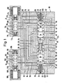
- Fig. 1 schematisch mit Schnitt das Sicherheitsventil in Grundstellung zeigt.
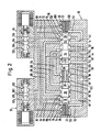
- Fig. 2 zeigt im Schnitt das Sicherheitsventil in Schaltstellung.
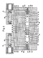
- Fig. 3 und 4 zeichen schmeatisch im Schnitt das Sicherheitsventil jeweils bei einer Fehlschaltung.
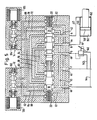
- Fig. 5 zeigt schematisch im Schnitt das Sicherheitsventil gekoppelt mit einem Proportional-Druckminderventil.
- Fig. 1 zeigt schematisch ein 5/2-Wege-Sicherheitsventil mit einem
Gehäuse 10, an welchem zwei elektromagnetischbetätigbare Vorsteuerventile 12 und 14 angeflanscht sind.
- Fig. 1 shows schematically with section the safety valve in the basic position.
- Fig. 2 shows in section the safety valve in the switching position.
- Fig. 3 and 4 characters Schmeatisch in section, the safety valve each in the event of a malfunction.
- Fig. 5 shows schematically in section the safety valve coupled to a proportional pressure reducing valve.
- Fig. 1 shows schematically a 5/2-way safety valve with a
housing 10, on which two electromagnetically actuatedpilot valves
Im Gehäuse ist eine zentrale Bohrung 16 ausgebildet, in der zwei Ventilkörper 18, 20 axial gegenläufig zueinander bewegbar sind. Jeder Ventilkörper ist mit einem Arbeitskolben 22 versehen, der eine nicht näher bezeichnete Sackbohrung aufweist, in der eine Druckfeder 24 angeordnet ist und die beiden Druckfedern 24 suchen die beiden Ventilkörper 18, 20 axial aufeinanderzu zu drücken, wobei in der in Fig. 1 gezeigten Grundstellung, in der die beiden Vorsteuerventile 12, 14 nicht erregt sind, die beiden Ventilkörper 18, 20 mit ihren Stirnseiten aneinanderstoßen.A
Der Ventilkörper 18 ist mit Steuerkolben 26, 28, 30 und der Ventilkörper 20 ist mit Steuerkolben 32, 34, 36 versehen.The
Ferner hat jeder der Arbeitskolben 22 eine Querbohrung 38, welche die jeweilige Sackbohrung des Arbeitskolbens mit dem Raum außerhalb des Arbeitskolbens verbindet und in eine am Umfang des jeweiligen Arbeitskolbens ausgebildete Ringnut l20 mündet.Furthermore, each of the working
Die zentrale Bohrung 16 ist mit in axialen Abständen angeordneten und in Ebenen quer zu ihrer Achse liegenden Ringkanälen78, 80, 82, 84 86, 88, 90, 92, 94, 96, sowie einseitigen Taschen 74, 76, 98 und 100 versehen.The
Die Ringkanäle und Taschen bilden mit dem Gehäuse zusammen Steuerkanten, mit denen die vorgenannten Steuerkolben zusammenwirken.The ring channels and pockets together with the housing form control edges with which the aforementioned control pistons interact.
Das Sicherheitsventil hat einen Pumpenanschluß P, Arbeitsanschlüsse A und B sowie Tankanschlüsse R und S.The safety valve has a pump connection P, working connections A and B and tank connections R and S.
Ein Kanal 40 verläuft vom Pumpenanschluß P zu einem Ringkanal 122 der zentralen Bohrung, ein Kanal 42 verläuft vom Arbeitsanschluß A zum Ringkanal 94, ein Kanal 44 verläuft vom Arbeitsanschluß B zum Ringkanal 90, ein Kanal 46 verläuft vom Tankanschluß R zum Ringkanal 78 und ein Kanal 48 verläuft vom Tankanschluß S zu einem Ringkanal 124 der zentralen Bohrung 16.A
Vom Kanal 46 zweigt ein Zweigkanal 50 ab, der in den Ringkanal 96 mündet und vom Kanal 40 gehen zwei Zweigkanäle 52 ab, von denen der eine über eine Ringnut des linken Arbeitskolbens 22 in die Tasche 76 mündet, während der andere über eine Ringnut des rechten Arbeitskolbens 22 in die Tasche 98 mündet.From the channel 46 branches off a
Ferner sind die Ringkanäle 86 und 92 durch einen Verbindungskanal 54 verbunden, die Ringkanäle 84 und 90 sind durch einen Verbindungskanal 56 verbunden, die Ringkanäle 82 und 88 sind durch einen Verbindungskanal 58 verbunden, und die Ringkanäle 80, 94 sind durch einen Verbindungskanal 60 miteinander verbunden.Furthermore, the
Das Vorsteuerventil 12 ist mit einem Kolben 102 versehen, der in einer Bohrung des Ventilgehäuses axial hin- und herbewegbar ist. Er wird durch Druckfedern 108, die in Federkammern 110 angeordnet sind, bei nicht erregtem Elektromagneten 106 in der in Fig. 1 gezeigten Grundstellung gehalten. Die Federkammern 110 stehen über einen Verbindungskanal 112 ständig in Verbindung miteinander. Die zentrale Bohrung ist mit in axialen Abständen ausgebildeten Ringkanälen 126, 128, 130 versehen.The
Das Vorsteuerventil 14 hat einen in einer Axialbohrung hin- und herbewegbaren Kolben 104, der durch Druckfedern 114, die in Federkammern 116 angeordnet sind,bei nicht-erregtem Elektromagneten 106 in der in Fig. 1 gezeigten Grundstellung gehalten ist. Die beiden Federkammern 116 stehen über einen Verbindungskanal 118 ständig in Verbindung miteinander. Die zentrale Bohrung ist mit in axialen Abständen ausgebildeten Ringkanälen 132, 134 und 136 versehen.The
Im Gehäuse des Sicherheitsventils sind ferner Steuerkanäle 62, 64, 66 und 68, 70, 72 ausgebildet, wobei der Steuerkanal 62 von der Tasche 74 zum Ringkanal 128 des Vorsteuerventiles 12 führt; der Steuerkanal 64 führt von der Tasche 76 zum Ringkanal 132 des Vorsteuerventils 14; der Steuerkanal 66 führt vom Ringkanal 78 zum Ringkanal 126 des Vorsteuerventils 12. Der Steuerkanal 68 führt von Tasche 100 zum Ringkanal 134 des Vorsteuerventils 14; der Steuerkanal 70 führt von Tasche 98 zum Ringkanal 130 des Vorsteuerventils 12 und der Steuerkanal 72 führt vom Ringkanal 96 zum Ringkanal 136 des Vorsteuerventils 14.
Das erfindungsgemäße Sicherheitsventil arbeitet wie folgt. In Fig. 1 ist die Grundstellung gezeigt, in der die beiden Elektromagneten 106 der Vorsteuerventile 12, 14 nicht erregt sind. Der linke Arbeitskolben 22 wird vom Zulauf P über den rechten Zweigkanal 52, den Steuerkanal 70, das Vorsteuerventil 12 und den Steuerkanal 62 mit dem Pumpendruck beaufschlagt; entsprechend wird der rechte Arbeitskolben 22 über den linken Zweigkanal 52, den Steuerkanal 64, das Vorsteuerventil 14 und den Steuerkanal 68 mit dem Pumpendruck beaufschlagt. Da aber auch in der zentralen Bohrung 16 über den Kanal 40 und eine nicht näher bezeichnete Längs- und Querbohrung im Ventilkörper 18 Pumpendruck herrscht, heben sich diese Drücke auf und die beiden Ventilkörper 18, 20 werden durch ihre Federn 24 aufeinanderzu gedrückt, bis sie mit ihren Stirnflächen aneinanderstoßen und die in Fig. 1 gezeigte Grundstellung einnehmen. In dieser Stellung des Sicherheitsventiles ist der Pumpenanschluß P über den Kanal 40, den Ringkanal 122, den Ringkanal 84, den Verbindungskanal 56 und den Ringkanal 90 mit dem Kanal 44 und damit mit dem Arbeitsanschluß B verbunden. Der Arbeitsanschluß A ist hingegen über den Kanal 42, den Ringkanal 94, den Ringkanal 96 und den Zweigkanal 50 mit dem Kanal 46 und damit mit dem Tankanschluß R verbunden (außerdem auch über 60, 80, 78 und 46).The safety valve according to the invention works as follows. 1 shows the basic position in which the two
In der in Fig. 2 gezeigten Schaltstellung sind die Vorsteuerventile 12 und 14 angesteuert, ihre Magnete erregt und ihre Kolben 102, 104 in ihre Schaltstellung umgeschaltet. Der linke Arbeitskolben 22 ist über seine Querbohrung 38, die Ringnut 120, die Tasche 74, den Steuerkanal 62, das Vorsteuerventil 12, den Steuerkanal 66 und die Ringnut 78 an den Kanal 46 und damit an den Tankanschluß R angeschlossen. Der rechte Arbeitskolben 22 ist über seine Querbohrung 38, die Ringnut 120, die Tasche 100, den Steuerkanal 68, das Vorsteuerventil 14, den Steuerkanal 72, den Ringkanal 96 und den Zweigkanal 50 ebenfalls an den Tankanschluß R angeschlossen. Da in der zentralen Bohrung 16 vom Pumpenanschluß P her über den Kanal 40 und über die nicht näher bezeichneten Bohrungen im Ventilkörper 18 der volle Pumpendruck herrscht, werden die beiden Ventilkörper axial voneinander weg gedrückt, bis zum Anschlag ihrer Arbeitskolben 22 am Gehäuse, wie Fig. 2 zeigt.In the switching position shown in FIG. 2, the
In dieser Schaltstellung ist der Pumpenanschluß P über den Kanal 40, die Ringkanäle 122, 86, den Verbindungskanal 54 und die Ringkanäle 92, 94 mit dem Kanal 42 und damit mit dem Arbeitsanschluß A verbunden. Der andere Arbeitsanschluß B ist über den Kanal 44, den Ringkanal 90, den Verbindungskanal 56, den Ringkanal 84, den Ringkanal 82, den Verbindungskanal 58 und die Ringkanäle 88 und 124 an den anderen Tankanschluß S angeschlossen.In this switching position, the pump connection P is connected to the
Die Fig. 3 und 4 zeigen zwei Fehlschaltungen, wobei in Fig. 3 das Vorsteuerventil 12 nicht geschaltet hat, während das Vorsteuerventil 14 geschaltet hat, wogegen in Fig. 4 umgekehrt das Vorsteuerventil 12 geschaltet und das Vorsteuerventil 14 nicht geschaltet hat.3 and 4 show two incorrect switching operations, the
In beiden Fehlschaltungen ist der Pumpenanschluß P mit dem Arbeitsanschluß B verbunden, während der Arbeitsanschluß A an den Tankanschluß R angeschlossen ist.In both faulty circuits, the pump connection P is connected to the working connection B, while the working connection A is connected to the tank connection R.
Bei der Fehlschaltung nach Fig. 3 geht die Verbindung vom Pumpenanschluß P über den Ringkanal 84 und den Verbindungskanal 56 zum Ringkanal 90 und damit zum Arbeitsanschluß B, während der Arbeitsanschluß A über den Ringkanal 94 und den Verbindungskanal 60 sowie die Ringkanäle 80, 78 mit dem Tankanschluß R verbunden ist.3, the connection from the pump connection P via the
In der Fehlschaltung nach Fig. 4 ist der Arbeitsanschluß B über die Ringkanäle 90, 92, den Verbindungskanal 54 und die Ringkanäle 86, 122 an den Pumpenanschluß P angeschlossen, während der Arbeitsanschluß A über die Ringkanäle 94, 96 und den Zweigkanal 50 mit dem Tankanschluß R in Verbindung steht.4, the working connection B is connected to the pump connection P via the
Bei der Fehlschaltung nach Fig. 3 herrscht in der Federkammer 138 des linken Arbeitskolbens der volle Pumpendruck, da diese Federkammer über die Querbohrung 38 und die Ringnut 120 an den vom Pumpenanschluß P kommenden Zweigkanal 52 angeschlossen ist. Der rechte Arbeitskolben 22 ist hingegen druckentlastet, da er über den Steuerkanal 68, das Vorsteuerventil 14, den Steuerkanal 72 und den Ringkanal 96 sowie den Zweigkanal 50 mit dem Tankanschluß R verbunden ist. In Fig. 4 ist dies genau umgekehrt, hier ist die Federkammer 138 des rechten Arbeitskolbens 22 über den Zweigkanal 52 an den Pumpenanschluß P angeschlossen, während der linke Arbeitskolben 22 über den Steuerkanal 62, das Vorsteuerventil 12 und den Steuerkanal 60 sowie den Ringkanal 78 mit dem Tankanschluß R verbunden und damit druckentlastet ist.3, there is full pump pressure in the
Diese Fehlschaltungen können auch durch nachträgliche Schaltung des defekten Gliedes nicht aufgehoben werden. Wenn beispielsweise in Fig. 3 das Vorsteuerventil 12 noch nachträglich schalten würde, so würde zwar die jetzt unter Pumpendruck stehende Steuerleitung 62 über die Steuerleitung 66 druckentlastet werden, der linke Arbeitskolben 22 bleibt aber weiterhin durch den vollen Pumpendruck beaufschlagt (über 52, 120 und 38), wie oben erläutert wurde. Weiterhin kann die rechte Federkammer 138 auch durch Umschalten des Ventiles 14 nicht mehr mit Druck beaufschlagt werden, da der Druckanschluß vom Ventil 14 über den Kanal 64, die Tasche 76, den Ringkanal 78, und den Kanal 46 mit dem Tankanschluß R verbunden ist. Entsprechendes gilt für die Fehlschaltung nach Fig. 4.These faulty switching operations cannot be canceled even by switching the defective link afterwards. If, for example in FIG. 3, the
Um das Ventil nach einer Fehlschaltung wieder funktionsfähig zu machen, müssen daher zuerst die Fehler beiseitigt und das Ventil durch Druckentlastung an P wieder in die Grundstellung gebracht werden.In order to make the valve functional again after a malfunction, the errors must first be eliminated and the valve returned to the basic position by relieving pressure at P.
Fig. 5 zeigt das erfindungsgemäße Sicherheitsventil in Schaltstellung gekoppelt mit einem Proportional-Dreiwege-Druckminderventil, nachfolgend aus Gründen der Einfachheit nur "Druckminderventil" genannt.FIG. 5 shows the safety valve according to the invention in the switching position coupled with a proportional three-way pressure reducing valve, hereinafter simply called "pressure reducing valve" for reasons of simplicity.
Wie Fig. 5 zeigt, ist das Druckminderventil 140 auf einer Seite über eine Leitung 49 ständig an den Tankanschluß 5 angeschlossen, während seine andere Seite je nach Schaltstellung über eine Leitung 142 mit dem Pumpenanschluß P oder über eine Leitung 144 mit dem Tankanschluß R verbunden werden kann.As shown in FIG. 5, the
Die Arbeitsanschlüsse A und B sind über Leitungen 43, 45 an einen Verbraucher angeschlossen, z.B. an einen Differentialzylinder 146 mit Kolben 148, wobei die Leitung 43 vom Arbeitsanschluß A zum kolbenstangenseitigen Raum 152 und die Leitung 45 vom Arbeitsanschluß B zum zylinderseitigen Raum 150 des Differentialzylinders 146 führt.The working connections A and B are connected to a consumer via lines 43, 45, e.g. to a
Das Ventil nach Fig. 5 arbeitet folgendermaßen. Das Sicherheitsventil befindet sich in Schaltstellung, in der, wie oben bereits ausgeführt, der Pumpenanschluß P mit dem Arbeitsanschluß A verbunden ist, während der Arbeitsanschluß B mit dem Tankanschluß S verbunden ist.5 operates as follows. The safety valve is in the switch position, in which, as already stated above, the pump connection P is connected to the working connection A, while the working connection B is connected to the tank connection S.
Durch entsprechende Einstellung des Druckes am Druckminderventil kann nun die Bewegungsrichtung des Kolbens 148 umgekehrt und seine Geschwindigkeit gesteuert werden.The direction of movement of the
Wird am Druckminderventil der Sekundärdruck beispielsweise auf Null bar eingestellt, so strömt das Druckmittel, d.h. das Öl, aus dem zylinderseitigen Raum 150 über B nach S und von dort über das Druckminderventil 140 und die Leitung 144 zum Tankanschluß R ab. Am Anschluß A und damit im kolbenstangenseitigen Raum 152 des Differentialzylinders 146 herrscht dagegen der volle Pumpendruck, so daß sich der Kolben 148 nach links in Fig. 5 bewegt. Durch entsprechende Einstellung des Sekundärdruckes am Druckminderventil 140 kann nun das Abströmen des Öls aus dem Raum 150 gesteuert und damit die Geschwindigkeit, mit der sich der Kolben 148 vorwärts bewegt, eingestellt werden.If, for example, the secondary pressure on the pressure reducing valve is set to zero bar, the pressure medium flows, i.e. the oil, from the cylinder-
Wird hingegen am Druckminderventil der Sekundärdruck auf den Pumpendruck eingestellt, so strömt Öl vom Pumpenanschluß P über die Leitung 142, das Druckminderventil 140 und den Tankanschluß S zum Arbeitsanschluß B. Da der Arbeitsanschluß A auch weiterhin an den Pumpenanschluß P angeschlossen ist, herrscht sowohl im zylinderseitigen Raum 150 als auch im kolbenstangenseitigen Raum 152 des Differentialzylinders 146 der Pumpendruck, da aber die Kolbenstirnfläche auf der Seite des Raumes 150 größer ist als die Kolbenstirnfläche auf der Seite des Raumes 152 (wegen der Kolbenstange), bewegt sich der Kolben 148 nach rechts in Fig. 5. Das hierdurch aus dem Raum 152 verdrängte Öl strömt über A nach P ab.If, on the other hand, the secondary pressure on the pressure reducing valve is set to the pump pressure, oil flows from the pump connection P via the
Geht der Kolben 148 auf Anschlag, z.B. an einem Werkstück, so läßt sich die Anpreßkraft durch das Druckminderventil 140 einstellen, wobei die Anpreßkraft nach rechts maximal ist, wenn am Arbeitsanschluß B der volle Pumpendruck herrscht, während die Anpreßkraft nach links maximal ist, wenn der Arbeitsanschluß 8 über den Anschluß 5 und′ das Druckminderventil 140 zum Tankanschluß R voll entlastet ist.If the
Bei einer Fehlschaltung ist das Druckminderventil 140 außer Funktion, weil der Anschluß S bei jeder Fehlschaltung gesperrt ist.In the event of a malfunction, the
Der Kolben 148 läuft dann nach rechts auf Anschlag, da bei jeder Fehlschaltung, wie oben bereits erläutert, der Arbeitsanschluß A zum Tankanschluß R entlastet, der Arbeitsanschluß B hingegen an den Pumpenanschluß P angeschlossen ist.The
Mit Hilfe des Druckminderventiles ist es somit möglich, den Druckaufbau und -abbau im Differentialzylinder 146 zu steuern, die Geschwindigkeit des Kolbens 148 einzustellen und seine Bewegungsrichtung umzukehren.With the help of the pressure reducing valve, it is thus possible to control the pressure build-up and reduction in the
Claims (2)
Applications Claiming Priority (2)
| Application Number | Priority Date | Filing Date | Title |
|---|---|---|---|
| DE3817122A DE3817122A1 (en) | 1988-05-19 | 1988-05-19 | SAFETY VALVE |
| DE3817122 | 1988-05-19 |
Publications (2)
| Publication Number | Publication Date |
|---|---|
| EP0347562A2 true EP0347562A2 (en) | 1989-12-27 |
| EP0347562A3 EP0347562A3 (en) | 1990-10-17 |
Family
ID=6354732
Family Applications (1)
| Application Number | Title | Priority Date | Filing Date |
|---|---|---|---|
| EP19890107714 Withdrawn EP0347562A3 (en) | 1988-05-19 | 1989-04-27 | Safety valve |
Country Status (4)
| Country | Link |
|---|---|
| US (1) | US4903728A (en) |
| EP (1) | EP0347562A3 (en) |
| JP (1) | JPH0242289A (en) |
| DE (1) | DE3817122A1 (en) |
Cited By (1)
| Publication number | Priority date | Publication date | Assignee | Title |
|---|---|---|---|---|
| EP3091239A1 (en) * | 2015-04-30 | 2016-11-09 | Hydac Fluidtechnik GmbH | Safety device |
Families Citing this family (7)
| Publication number | Priority date | Publication date | Assignee | Title |
|---|---|---|---|---|
| US6478049B2 (en) | 1996-12-16 | 2002-11-12 | Ross Operating Valve Company | Double valve with anti-tiedown capability |
| US5927324A (en) * | 1996-12-16 | 1999-07-27 | Ross Operating Valve Company | Cross flow with crossmirror and lock out capability valve |
| US6155293A (en) | 1996-12-16 | 2000-12-05 | Ross Operating Valve Company | Double valve with anti-tiedown capability |
| ATE352723T1 (en) | 2001-05-04 | 2007-02-15 | Ross Operating Valve Co | CONTROL VALVE SYSTEM |
| US6619369B2 (en) * | 2001-08-08 | 2003-09-16 | Try Co., Ltd. | Process for producing a thin die-cast molded article of an aluminum material |
| WO2015004003A1 (en) * | 2013-07-08 | 2015-01-15 | Norgren Gmbh | A safety valve |
| US9903396B2 (en) * | 2016-03-08 | 2018-02-27 | Caterpillar Inc. | Valve assembly |
Citations (6)
| Publication number | Priority date | Publication date | Assignee | Title |
|---|---|---|---|---|
| US3171435A (en) * | 1961-12-05 | 1965-03-02 | Parker Hannifin Corp | Solenoid operated valve assembly |
| DE1245665B (en) * | 1963-01-23 | 1967-07-27 | Erich Herion | Control valve |
| DE1284231B (en) * | 1965-01-15 | 1969-02-20 | Herion Erich | Control device with two control valves |
| DE1750358A1 (en) * | 1968-04-24 | 1971-02-11 | Bosch Gmbh Robert | Electro-hydraulic control device |
| DD96321A1 (en) * | 1971-12-16 | 1973-03-12 | ||
| DE3104957C2 (en) * | 1981-02-12 | 1986-12-04 | Herion-Werke Kg, 7012 Fellbach | Hydraulically operated press safety valve |
-
1988
- 1988-05-19 DE DE3817122A patent/DE3817122A1/en not_active Withdrawn
-
1989
- 1989-04-26 US US07/344,351 patent/US4903728A/en not_active Expired - Fee Related
- 1989-04-27 EP EP19890107714 patent/EP0347562A3/en not_active Withdrawn
- 1989-05-18 JP JP1125496A patent/JPH0242289A/en active Pending
Patent Citations (6)
| Publication number | Priority date | Publication date | Assignee | Title |
|---|---|---|---|---|
| US3171435A (en) * | 1961-12-05 | 1965-03-02 | Parker Hannifin Corp | Solenoid operated valve assembly |
| DE1245665B (en) * | 1963-01-23 | 1967-07-27 | Erich Herion | Control valve |
| DE1284231B (en) * | 1965-01-15 | 1969-02-20 | Herion Erich | Control device with two control valves |
| DE1750358A1 (en) * | 1968-04-24 | 1971-02-11 | Bosch Gmbh Robert | Electro-hydraulic control device |
| DD96321A1 (en) * | 1971-12-16 | 1973-03-12 | ||
| DE3104957C2 (en) * | 1981-02-12 | 1986-12-04 | Herion-Werke Kg, 7012 Fellbach | Hydraulically operated press safety valve |
Cited By (1)
| Publication number | Priority date | Publication date | Assignee | Title |
|---|---|---|---|---|
| EP3091239A1 (en) * | 2015-04-30 | 2016-11-09 | Hydac Fluidtechnik GmbH | Safety device |
Also Published As
| Publication number | Publication date |
|---|---|
| JPH0242289A (en) | 1990-02-13 |
| US4903728A (en) | 1990-02-27 |
| EP0347562A3 (en) | 1990-10-17 |
| DE3817122A1 (en) | 1989-11-30 |
Similar Documents
| Publication | Publication Date | Title |
|---|---|---|
| DE1921977C3 (en) | Valve device for controlling the pressure medium paths of a double-acting servo motor | |
| DE2232857C2 (en) | Control device for a hydraulically driven implement | |
| DE2328658C2 (en) | Spool assembly | |
| DE2258853B2 (en) | THREE- OR MULTI-WAY VALVE IN SEAT DESIGN | |
| DE2333174C3 (en) | Hydraulic vehicle braking system | |
| DE3817120A1 (en) | SAFETY VALVE | |
| DE2511986C2 (en) | Hydraulic adjusting device for controlling the position of an adjusting piston | |
| DE3710699C1 (en) | Hydraulic control device for a consumer group | |
| EP0347562A2 (en) | Safety valve | |
| EP0342409A2 (en) | Safety valve | |
| DE3225132A1 (en) | Hydraulic safety brake valve | |
| DE4314801A1 (en) | Hydraulic system, in particular for a folding press | |
| DE3214845A1 (en) | DEVICE FOR ACTUATING A SLIDING BODY, IN PARTICULAR THE PISTON SLIDER OF A DIRECTIONAL VALVE | |
| DE2801689C2 (en) | Control valve device | |
| CH509535A (en) | Safety valve for pressure medium operated devices | |
| DE4418881A1 (en) | Electrohydraulic control system and control valve for farm vehicle lifting gear | |
| DE8612453U1 (en) | Safety valve | |
| DE3519148C2 (en) | ||
| DE2705674C3 (en) | Hydraulic servo motor system | |
| DE3736750C2 (en) | ||
| DE4435339A1 (en) | Arrangement for controlling a hydraulically actuated main valve | |
| DE3147030A1 (en) | Solenoid valve unit | |
| EP0005818B1 (en) | Hydraulically operated 3-way seat valve | |
| DE19535677A1 (en) | Device for controlling a hydraulic motor | |
| DE8806587U1 (en) | Safety valve |
Legal Events
| Date | Code | Title | Description |
|---|---|---|---|
| PUAI | Public reference made under article 153(3) epc to a published international application that has entered the european phase |
Free format text: ORIGINAL CODE: 0009012 |
|
| AK | Designated contracting states |
Kind code of ref document: A2 Designated state(s): CH DE FR GB IT LI SE |
|
| PUAL | Search report despatched |
Free format text: ORIGINAL CODE: 0009013 |
|
| AK | Designated contracting states |
Kind code of ref document: A3 Designated state(s): CH DE FR GB IT LI SE |
|
| 17P | Request for examination filed |
Effective date: 19901128 |
|
| 17Q | First examination report despatched |
Effective date: 19920302 |
|
| STAA | Information on the status of an ep patent application or granted ep patent |
Free format text: STATUS: THE APPLICATION IS DEEMED TO BE WITHDRAWN |
|
| 18D | Application deemed to be withdrawn |
Effective date: 19930304 |