EP0347523B1 - Disc brake with non-interchangeable brake pads - Google Patents
Disc brake with non-interchangeable brake pads Download PDFInfo
- Publication number
- EP0347523B1 EP0347523B1 EP89103376A EP89103376A EP0347523B1 EP 0347523 B1 EP0347523 B1 EP 0347523B1 EP 89103376 A EP89103376 A EP 89103376A EP 89103376 A EP89103376 A EP 89103376A EP 0347523 B1 EP0347523 B1 EP 0347523B1
- Authority
- EP
- European Patent Office
- Prior art keywords
- brake
- disc brake
- carrier
- housing
- recess
- Prior art date
- Legal status (The legal status is an assumption and is not a legal conclusion. Google has not performed a legal analysis and makes no representation as to the accuracy of the status listed.)
- Expired - Lifetime
Links
- 238000005266 casting Methods 0.000 claims description 4
- 238000000034 method Methods 0.000 claims description 3
- 238000013459 approach Methods 0.000 description 9
- 238000009434 installation Methods 0.000 description 3
- 238000004519 manufacturing process Methods 0.000 description 3
- 238000004049 embossing Methods 0.000 description 2
- 238000004080 punching Methods 0.000 description 2
- 238000003754 machining Methods 0.000 description 1
Images

Classifications
-
- F—MECHANICAL ENGINEERING; LIGHTING; HEATING; WEAPONS; BLASTING
- F16—ENGINEERING ELEMENTS AND UNITS; GENERAL MEASURES FOR PRODUCING AND MAINTAINING EFFECTIVE FUNCTIONING OF MACHINES OR INSTALLATIONS; THERMAL INSULATION IN GENERAL
- F16D—COUPLINGS FOR TRANSMITTING ROTATION; CLUTCHES; BRAKES
- F16D55/00—Brakes with substantially-radial braking surfaces pressed together in axial direction, e.g. disc brakes
- F16D55/02—Brakes with substantially-radial braking surfaces pressed together in axial direction, e.g. disc brakes with axially-movable discs or pads pressed against axially-located rotating members
- F16D55/22—Brakes with substantially-radial braking surfaces pressed together in axial direction, e.g. disc brakes with axially-movable discs or pads pressed against axially-located rotating members by clamping an axially-located rotating disc between movable braking members, e.g. movable brake discs or brake pads
- F16D55/224—Brakes with substantially-radial braking surfaces pressed together in axial direction, e.g. disc brakes with axially-movable discs or pads pressed against axially-located rotating members by clamping an axially-located rotating disc between movable braking members, e.g. movable brake discs or brake pads with a common actuating member for the braking members
-
- F—MECHANICAL ENGINEERING; LIGHTING; HEATING; WEAPONS; BLASTING
- F16—ENGINEERING ELEMENTS AND UNITS; GENERAL MEASURES FOR PRODUCING AND MAINTAINING EFFECTIVE FUNCTIONING OF MACHINES OR INSTALLATIONS; THERMAL INSULATION IN GENERAL
- F16D—COUPLINGS FOR TRANSMITTING ROTATION; CLUTCHES; BRAKES
- F16D65/00—Parts or details
- F16D65/02—Braking members; Mounting thereof
- F16D65/04—Bands, shoes or pads; Pivots or supporting members therefor
- F16D65/092—Bands, shoes or pads; Pivots or supporting members therefor for axially-engaging brakes, e.g. disc brakes
- F16D65/095—Pivots or supporting members therefor
-
- F—MECHANICAL ENGINEERING; LIGHTING; HEATING; WEAPONS; BLASTING
- F16—ENGINEERING ELEMENTS AND UNITS; GENERAL MEASURES FOR PRODUCING AND MAINTAINING EFFECTIVE FUNCTIONING OF MACHINES OR INSTALLATIONS; THERMAL INSULATION IN GENERAL
- F16D—COUPLINGS FOR TRANSMITTING ROTATION; CLUTCHES; BRAKES
- F16D65/00—Parts or details
- F16D65/02—Braking members; Mounting thereof
- F16D2065/026—Braking members; Mounting thereof characterised by a particular outline shape of the braking member, e.g. footprint of friction lining
Definitions
- the swapping of the inner and outer brake pads is precluded by the fact that the two brake pads are equipped with different projections which protrude circumferentially from the back plates.
- the projections are provided with support surfaces which bear against associated complementarily shaped support surfaces of the brake carrier.
- the support surfaces of the inner brake pad are semicircular, those of the outer brake pad rectangular, so that the brake pads cannot be installed if they are mixed up.
- the brake is closed at the top by a housing 6, which is supported on its piston-side end on two bolts (not shown) and on its visible rear end in the radial and tangential direction on the two lateral guide ends 8 of the rear brake pad 5.
- the guide ends 7 of the front brake pad or the guide ends 8 of the rear brake pad have a hammer-like shape, the end faces 9 and 10 of the front brake pad 7 and the rear brake pad 8 for absorbing tangentially directed braking forces on the assigned surfaces of the support arms 2 and 3 issue.
- the lugs 13, 14 can extend over the entire length of the support arms 2, 3 in the axial direction or else only over the part of the arms behind the brake disc (which is not shown broken with respect to arm 2). This depends on whether an unmistakable key should only be assigned to the piston-side (or outer) brake pad or whether two identical (but different compared to other brake types) brake pads should be installed unmistakably.
Landscapes
- Engineering & Computer Science (AREA)
- General Engineering & Computer Science (AREA)
- Mechanical Engineering (AREA)
- Braking Arrangements (AREA)
Description
In neuerer Zeit werden Bremsbeläge im wachsenden Maße immer mehr von ungeschulten Kräften eingebaut. Da nun Bremsen und insbesondere die Bremsbeläge für die Sicherheit eines Fahrzeugs besonders wichtige Bauteile sind, scheint es notwendig, hier Vorsichtsmaßnahmen zu treffen. Das Problem vergrößert sich insbesondere dadurch, daß an der gleichen Bremse vielfach unterschiedlich ausgestaltete Bremsklötze verwendet werden, um den immer höheren an die Leistung der Bremse zu stellenden Anforderungen gerecht zu werden. Diese voneinander abweichenden Bremsklötze werden dann in Form von Bausätzen den ungeschulten Kräften ausgehändigt.In recent times, brake pads are increasingly being installed by untrained personnel. Since brakes and especially the brake pads are particularly important components for the safety of a vehicle, it seems necessary to take precautionary measures here. The problem is exacerbated in particular by the fact that differently designed brake pads are used on the same brake in order to meet the ever increasing demands on the performance of the brake. These differing brake pads are then handed over to untrained personnel in the form of kits.
Aus der US-PS 44 73 137 ist es bekannt, den Einbau fehlerhafter Bremsklötze dadurch zu verhindern, daß diese nur mit Hilfe eines passenden Schlüssels montiert werden können. Das dort vorgeschlagene System ist aber nun insofern nachteilig, weil die Bremsbeläge auch ohne Schlüssel verbaut werden können, wobei eine falsche Einbaulage sowie mögliches Verlieren der Beläge nicht ausgeschlossen ist.From US-PS 44 73 137 it is known to prevent the installation of faulty brake pads by the fact that they can only be installed with the help of a suitable key. However, the system proposed there is disadvantageous in that the brake pads can also be installed without a key, whereby an incorrect installation position and possible loss of the pads cannot be ruled out.
Aus der DE-A-29 19 535 ist bekannt, einen kolbenseitigen Bremsklotz einer Schwimmsattel-Scheibenbremse mit einer Belagmasse zu versehen, die sich in Umfangsrichtung nicht über die gesamte Länge der Rückenplatte erstreckt, während sich die Belagmasse des äußeren Bremsklotzes bis an die Randbereiche der Rückenplatte erstrecken. Die Arme des Bremsträgers sind derart angeordnet, daß bei einer unabsichtlichen Vertauschung der beiden Bremsklötze die Belagmasse des äußeren Bremsklotzes in dem Randbereich an den Armen anstößt und damit der Bremsklotz nicht innenseitig eingesetzt werden kann.From DE-A-29 19 535 it is known to provide a piston-side brake block of a floating caliper disc brake with a lining mass which does not extend in the circumferential direction over the entire length of the back plate, while the lining mass of the outer brake block extends to the edge regions of the Extend back plate. The arms of the brake carrier are arranged in such a way that an unintentional Exchange of the two brake pads, the lining mass of the outer brake pad abuts the arms in the edge area and therefore the brake pad cannot be used on the inside.
Bei einer anderen Scheibenbremse, die aus de DE-A-25 49 865 bekannt ist, wird die Vertauschung von innerem und äußerem Bremsklotz dadurch ausgeschlossen, daß die beiden Bremsklötze mit unterschiedlichen Vorsprüngen ausgestattet sind, die in Umfangsrichtung von den Rückenplatten abstehen. Die Vorsprünge sind zur Abstützung der Umfangskräfte mit Abstützflächen versehen, die an zugehörigen komplementär ausgeformten Abstützflächen des Bremsträgers anliegen. Die Abstützflächen des inneren Bremsklotzes sind halbkreisförmig, die des äußeren Bremsklotzes rechteckförmig ausgestaltet, so daß bei einer Vertauschung die Bremsklötze nicht eingebaut werden können.In another disc brake, which is known from DE-A-25 49 865, the swapping of the inner and outer brake pads is precluded by the fact that the two brake pads are equipped with different projections which protrude circumferentially from the back plates. To support the circumferential forces, the projections are provided with support surfaces which bear against associated complementarily shaped support surfaces of the brake carrier. The support surfaces of the inner brake pad are semicircular, those of the outer brake pad rectangular, so that the brake pads cannot be installed if they are mixed up.
Die Erfindung geht daher aus von einer Scheibenbremse, der sich aus dem Oberbegriff des Hauptanspruchs ergebenden Gattung und hat sich zur Aufgabe gestellt, die Bremse selbst sowie die zugehörigen Beläge derart auszugestalten, daß in einfacher und kostengünstiger Weise nur die vorgesehenen Beläge an die vorgesehene Stelle eingebaut werden können.The invention is therefore based on a disc brake, which is derived from the preamble of the main claim and has set itself the task of designing the brake itself and the associated pads so that only the intended in a simple and inexpensive manner Coverings can be installed at the intended location.
Die Lösung der gestellten Aufgabe ergibt sich aus der aus dem kennzeichnenden Teil des Hauptanspruchs ersichtlichen Merkmalskombination. Die Erfindung besteht im Prinzip also darin, an den Führungsflächen des Trägers und/oder des Gehäuses sowie an den zugehörigen Flächen der Trägerplatte des Bremsklotzes Ausnehmungen bzw. Vorsprünge vorzusehen, welche in Form eines fest mit der Bremse bzw. den Bremsklötzen verankerten Schlüssels nur den Einbau des richtigen Bremsklotzes an der richtigen Stelle gestatten.The solution to the problem arises from the combination of features evident from the characterizing part of the main claim. In principle, the invention therefore consists in providing recesses or projections on the guide surfaces of the carrier and / or the housing and on the associated surfaces of the carrier plate of the brake block, which in the form of a key firmly anchored to the brake or the brake blocks, only the installation allow the right brake pad in the right place.
Üblicherweise werden die für die Rückenplatte des Bremsklotzes vorgesehenen Führungsflächen durch Räumen aus dem gegossenen Träger bzw. gegossenen Gehäuse herausgearbeitet. Derartige Räumwerkzeuge sind aber sehr teuer, so daß man bestrebt ist, das gleiche Räumwerkzeug möglichst oft und damit bei an sich voneinander abweichenden Bremsen einzusetzen. Um nun trotz der gewünschten Verschlüsselung der Führungsflächen mit sich änderndem Schlüssel nicht das Räumwerkzeug auswechseln zu müssen, empfiehlt sich in Weiterbildung der Erfindung eine Merkmalskombination gemäß den Ansprüchen 2 und 3. Diese Verbesserung besteht im wesentlichen darin, die verschlüsselnden Ansätze nicht durch Räumen herauszuarbeiten, sondern sie schon während des Gießvorgangs an geeigneten Stellen an dem Gehäuse oder dem Träger anzugießen, wie sie in Anspruch 2 genauer beschrieben sind.Usually, the guide surfaces provided for the back plate of the brake pad are worked out of the cast carrier or cast housing by broaching. However, broaching tools of this type are very expensive, so that efforts are made to use the same broaching tool as often as possible and thus with brakes which differ from one another. In order not to have to change the broaching tool despite the desired encryption of the guide surfaces with a changing key, a combination of features according to
Um die Maßnahmen nach Anspruch 2 oder 3 durchzuführen, ist es günstig, die Merkmalskombination nach Anspruch 4 zu wählen, da hier geometrisch der ausreichende Platz für entsprechende Ansätze an den Trägerarmen zur Verfügung steht. Im übrigen ist es wichtig, diese Ansätze möglichst nicht an Flächen vorzusehen, die durch erhebliche Kräfte, wie beispielsweise die in tangentialer Richtung aufzunehmenden Bremskräfte, belastet sind.In order to carry out the measures according to
Die dem Ansatz an der Bremse entsprechende Ausnehmung an der Rückenplatte läßt sich vorteilhaft durch die in Anspruch 5 angegebene Maßnahme gewinnen. Das hierfür notwendige Stanzverfahren ist relativ einfach und flexibel handhabbar.The recess on the back plate corresponding to the approach on the brake can advantageously be obtained by the measure specified in
Um die unterschiedlich verschlüsselten Bremsklötze, bis auf die Verschlüsselung möglichst in der gleichen Serie herstellen zu können, empfiehlt sich in Weiterbildung der Erfindung die Merkmalskombination nach Anspruch 6. Es werden also erst nach dem Aufbringen der Beläge die für einen bestimmten Bremsentyp als Schlüssel dienenden Ausnehmungen aus der Rückenplatte des Bremsklotzes herausgestanzt.In order to be able to produce the differently encrypted brake pads, with the exception of the encryption, if possible, in the same series, the feature combination according to
In der Praxis spielt sich der Versuch, einen falschen Bremsklotz in die Bremse einzubauen dergestalt ab, daß wegen der fehlenden Ausnehmung in der falschen Rückenplatte der Bremsklotz auf dem als Schlüssel liegenden Ansatz aufliegt und daher gegenüber dem ordnungsgemäßen, in Höhe des Schlüsselansatzes ein entsprechender Ausnehmung aufweisenden Bremsklotz in radialer Richtung höher liegt. Hierdurch läßt sich aber das Gehäuse nicht montieren (Bolzen können nicht eingeschraubt werden) und der Gehäusedeckel der Bremse nicht mehr schließen, so daß die Arbeiten an der Bremse mit falschem Bremsklotz nicht mehr fortgeführt werden können.In practice, the attempt to install a wrong brake pad in the brake takes place in such a way that, due to the missing recess in the wrong back plate, the brake pad rests on the approach lying as the key and therefore has a corresponding recess compared to the proper one at the level of the key approach Brake pad is higher in the radial direction. This means that the housing cannot be installed (bolts cannot be screwed in) and the housing cover of the brake can no longer be closed, so that work on the Brake with wrong brake pad can no longer be continued.
Eine andere eventuell zusätzliche Verschlüsselungsmöglichkeit des Bremsträgers bzw. des Gehäuses wird in Anspruch 7 vorgeschlagen. Diese Art der Verschlüsselung wird in vorteilhafter Weise durch eine Verschlüsselung der Trägerplatte gemäß Anspruch 8 ergänzt. Auch die durch Prägen der Trägerplatte sich ergebenden Ansätze lassen gemäß Anspruch 9 eine Verschlüsselung zu, nachdem der Bremsklotz in Serienherstellung bereits mit einem Bremsbelag versehen wurde. Die Merkmale gemäß Anspruch 7 bis 9 sind hervorragend geeignet, um beispielsweise die Verwechslung zweier zu einem Bausatz gehörender Bremsbeläge einer Bremse zu verhindern, indem es beispielsweise unmöglich gemacht wird, den kolbenseitigen Bremsklotz an der äußeren Bremsenseite zu verbauen und umgekehrt.Another possible additional encryption option for the brake carrier or the housing is proposed in
Zwei Ausführungsbeispiele der Erfindung werden nachfolgend anhand der Zeichnung erläutert. Darin zeigt
- Fig. 1
- von der äußeren Seite her gesehen und in teilweise geschnittener Darstellung eine Scheibenbremse gemäß der Erfindung
- Fig. 2
- aus der Sicht von Fig. 1 in abgebrochener Darstellung einen gegenüber Fig. 1 modifizierten Träger
- Fig. 3
- eine Rückenplatte, die mit einem verschlüsselnden Ansatz versehen wurde sowie noch zusätzlich eine verschlüsselnde Ausnehmung enthält und
- Fig. 4
- eine vergrößerte Darstellung eines Teils der Rückenplatte nach Fig. 3.
- Fig. 1
- seen from the outside and in a partially sectioned view a disc brake according to the invention
- Fig. 2
- from the perspective of FIG. 1 in broken representation, a carrier modified compared to FIG. 1
- Fig. 3
- a back plate that has been provided with an encrypting approach and additionally contains an encrypting recess and
- Fig. 4
- 3 shows an enlarged illustration of a part of the back plate according to FIG. 3.
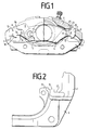
Fig. 1 zeigt von außen gesehen eine Teilbelag-Scheibenbremse. In dieser Beschreibung wird die dargestellte Bremse nur so weit beschrieben, wie es für das Verständnis der Erfindung unbedingt notwendig ist. Nähere Einzelheiten ergeben sich aus der DE-OS 37 07 156, in der die dargestellte Scheibenbremse näher erläutert ist.Fig. 1 shows a partial lining disc brake seen from the outside. In this description, the brake shown is only described as far as is absolutely necessary for an understanding of the invention. Further details can be found in DE-OS 37 07 156, in which the disc brake shown is explained in more detail.
Die Scheibenbremse nach Fig. 1 ist etwa in Höhe der senkrecht verlaufenden Symmetrieebene teilweise gebrochen dargestellt. Dabei ist die rechte Hälfte der Bremse etwa in Höhe des kolbenseitigen Bremsbelages aufgebrochen. Für die Erfindung wesentlich zeigt Fig. 1 den Träger der Scheibenbremse auf dessen Armen 2,3 sowohl der vordere kolbenseitige Bremsklotz 4, als auch der hintere äußere Bremsklotz 5 in axialer Richtung geführt werden.1 is shown partially broken approximately at the level of the perpendicular plane of symmetry. The right half of the brake has broken open approximately at the level of the brake lining on the piston side. 1 shows the carrier of the disc brake on its
Nach oben wird die Bremse durch ein Gehäuse 6 abgeschlossen, welches sich an seinem kolbenseitigen Ende auf zwei nicht dargestellten Bolzen und an seinem sichtbaren hinteren Ende in radialer und tangentialer Richtung an den beiden seitlichen Führungsenden 8 des hinteren Bremsklotzes 5 abstützt. Die Führungsenden 7 des vorderen Bremsklotzes bzw. die Führungsenden 8 des hinteren Bremsklotzes haben hammerförmige Gestalt, wobei die Stirnflächen 9 bzw. 10 des vorderen Bremsklotzes 7 bzw. des hinteren Bremsklotzes 8 zur Aufnahme tangential gerichteter Bremskräfte an den zugeordneten Flächen der Trägerarme 2 bzw. 3 anliegen.The brake is closed at the top by a
Für die Erfindung wesentlich sind nun zwei Ausnehmungen 11 und 12, die paarweise an dem vorderen Bremsklotz 7 bzw. dem hinteren Bremsklotz 8 angeordnet sind.Essential for the invention are now two
Diese Ausnehmungen 11 bzw. 12 schaffen Raum für zwei Ansätze 13,14, die sich ausgehend von den in radialer Richtung weisenden Stützflächen 15 und 16 der Trägerarme 2 und 3 in radialer Richtung weisen.These
Die Ansätze 13,14 können sich über die gesamte Länge der Trägerarme 2,3 in axialer Richtung erstrecken oder aber auch nur über den hinter der Bremsscheibe liegenden Teil der Arme (der hinsichtlich Arm 2 nicht gebrochen dargestellt ist). Dies richtet sich danach, ob nur dem kolbenseitigen (oder äußeren) Bremsklotz ein unverwechselbarer Schlüssel zugeordnet werden soll oder ob zwei gleichartige (aber gegenüber anderen Bremsentypen abweichende) Bremsklötze unverwechselbar eingebaut werden sollen.The
Die Herstellung der Ansätze 13,14 der Arme 2,3 geschieht zweckmäßigerweise dadurch, daß diese Ansätze beim Gießvorgang des Trägers 1 mit angegossen werden und anschließend bei einem Räumvorgang der mit ihren Wänden die Bremsklötze führenden Führungsräume 17,18 die Ansätze 13,14 besonders plastisch herausgearbeitet werden. Wie aus Fig. 2 ersichtlich, kann der Ansatz 13 durch Gießen mehr oder weniger breit gestaltet werden, ohne daß der durch das Räumwerkzeug bestimmte Querschnitt des Führungsraums geändert werden braucht.The manufacture of the
Die zu den Ansätzen 13,14 zugehörigen Ausnehmungen 11,12 der passenden Bremsklötze werden durch vorzugsweise Stanzen, aber auch durch eine andere Bearbeitungsart herausgearbeitet. Diese Bearbeitungsform ist preiswert und läßt sich auch bei verhältnismäßig kleinen Stückzahlen an bereits mit Belägen versehenen Bremsklötzen durchführen.The
In Fig. 2 ist der Ansatz 13 bis zum für den Betrachter sichtbaren hinteren Ende des Trägers durchgeführt und gegenüber dem Ansatz 13 in Fig. 1 verbreitert ausgestaltet. In Fig. 3 sind die beiden zugehörigen Ausnehmungen 11 an beiden Seiten des kolbenseitigen vorderen Bremsklotzes 4 zu erkennen, wobei dieser Bremsklotz ohne den zugehörigen Bremsbelag dargestellt wurde. Die an der Trägerplatte des Bremsklotzes 4 erkennbaren kreisförmigen Öffnungen haben für die Erfindung keine Bedeutung und dienen herstellungstechnischen Zwecken für den gesamten Belag.In FIG. 2 the
In Fig. 1 ist weiterhin an dem Führungsende 7 ein im wesentlichen kreissektorförmiger Ansatz 20 zu erkennen, der durch entsprechendes Prägen der oberen Hammerkopfhälfte herausgearbeitet ist. Dieser Ansatz schneidet die in axialer Richtung verlaufende Führungsfläche 23,24 des Gehäuses 6, so daß der Deckel nicht geschlossen werden könnte, wenn nicht in Höhe des in axialer Richtung verlaufenden Bewegungsraums des Führungselements 7 eine entsprechende Ausnehmung 25 in den Deckel eingearbeitet wäre.In Fig. 1, an essentially circular sector-shaped
Da diese Ausnehmung aber am äußeren, betrachterseitigen Ende des Gehäuses fehlt, könnte der Bremsklotz 7 nicht am äußeren Bremsenende eingebaut werden, sondern nur, wie in der Zeichnung gezeigt, kolbenseitig. Für das äußere Bremsenende eignet sich nur der Bremsklotz 5, der keinen dem Ansatz 20 entsprechenden Ansatz besitzt.However, since this recess is missing at the outer end of the housing on the observer side, the
Durch diese Maßnahme ist gewährleistet, daß der kolbenseitige Bremsklotz mit dem äußeren Bremsklotz nicht vertauscht werden kann.This measure ensures that the brake pad on the piston side cannot be interchanged with the outer brake pad.
In Fig. 3 ist an der zum Bremsklotz 4 gehörenden Trägerplatte der kreissektorförmige Ansatz 20 ebenfalls dargestellt, der in Fig. 4 noch vergrößert herausgezeichnet wurde. Die verschiedenen hier beschriebenen Verschlüsselungsarten können entweder einzeln oder kombiniert angewendet werden, so daß entweder bestimmte identische Beläge in die zugehörige Bremse eingebaut werden können oder aber auch sichergestellt werden kann, daß kolbenseitige Bremsklötze nicht mit den äußeren Bremsklötzen verwechselt werden können.In Fig. 3, the circular sector-shaped
Claims (10)
- A disc brake with noninterchangeable brake shoes (4, 5) in which the backplate of at least one brake shoe (4 or 5, respectively) takes axially slidably support at the carrier (1) in tangential and radial direction and on the said brake shoe (4 or 5, respectively), in its turn, the housing (6),
characterized in that projections (13, 14) or recesses (25) extending at least over the axial travel of the backplate (4, 5) are provided at one or at a plurality of guide areas (9, 10, 15, 16, 23, 24) of the carrier (1) and/or the housing (6), and in that the associated backplate (4, 5) is furnished with corresponding recesses (11, 12) or, respectively, projections (20) which are selected sufficiently large or, respectively, sufficiently small so that their contours (11, 12 or, respectively, 20) do not intersect the contours of the corresponding projections (13, 14) or, respectively, recesses (25) of the carrier (1) or, respectively, the housing (6). - A disc brake as claimed in claim 1,
characterized in that one guide area (15, 16) serving for the radial support of the backplate (4, 5) is provided with a projection (13, 14) extending in axial direction. - A disc brake as claimed in claim 2,
characterized in that the projection (13, 14) is cast on or worked on. - A disc brake as claimed in claim 2 or in claim 3,
characterized in that the projection (13, 14) surmounts the guide area (15, 16) of the carrier (1) in radial direction at the edge of the guide area (15, 16) pointing in the direction of the central plane of the brake and extends in axial direction. - A disc brake as claimed in any one of the claims 1 to 4,
characterized in that the recess (11, 12) of the backplate (4, 5) is punched out. - A disc brake as claimed in claim 5,
characterized in that the recess (11, 12) is punched out after the lining has been applied. - A disc brake as claimed in any one of the claims 1 to 6,
characterized in that the housing (6) is furnished with a recess (25) at an area (23, 24) pointing in tangential direction, the said recess (25) being formed by a casting process. - A disc brake as claimed in claim 7,
characterized in that the associated carrier plate (4) is furnished with a projection (20) which is formed by stamping. - A disc brake as claimed in claim 7,
characterized in that the stamping process takes place at the carrier plate (4) provided with a brake lining. - A disc brake as claimed in any one of the claims 2 to 4 or in claim 7,
characterized in that the projection (13, 14) or, respectively, the recess (25) is provided at the brake carrier (1) or, respectively, at the housing (6) only at the level of the piston-side brake shoe.
Applications Claiming Priority (2)
| Application Number | Priority Date | Filing Date | Title |
|---|---|---|---|
| DE3816109 | 1988-05-11 | ||
| DE3816109A DE3816109A1 (en) | 1988-05-11 | 1988-05-11 | DISC BRAKE WITH UNMISTAKABLE BRAKE PADS |
Publications (3)
| Publication Number | Publication Date |
|---|---|
| EP0347523A2 EP0347523A2 (en) | 1989-12-27 |
| EP0347523A3 EP0347523A3 (en) | 1990-08-16 |
| EP0347523B1 true EP0347523B1 (en) | 1993-08-25 |
Family
ID=6354169
Family Applications (1)
| Application Number | Title | Priority Date | Filing Date |
|---|---|---|---|
| EP89103376A Expired - Lifetime EP0347523B1 (en) | 1988-05-11 | 1989-02-27 | Disc brake with non-interchangeable brake pads |
Country Status (3)
| Country | Link |
|---|---|
| EP (1) | EP0347523B1 (en) |
| DE (2) | DE3816109A1 (en) |
| ES (1) | ES2042825T3 (en) |
Cited By (4)
| Publication number | Priority date | Publication date | Assignee | Title |
|---|---|---|---|---|
| DE102004002571A1 (en) * | 2003-04-28 | 2004-12-02 | Bpw Bergische Achsen Kg | Caliper for a disk brake, has a brake anchor plate with recesses to hold brake pads and guide surfaces to guide the brake pads on-axis regarding their feed travel |
| DE102004052541A1 (en) * | 2004-10-28 | 2006-05-04 | Bpw Bergische Achsen Kg | Brake caliper for a disc brake which is provided with recesses at both sides for inserting brake pads and have clutching equipment with heat guard plates |
| DE102008013514A1 (en) | 2008-03-11 | 2009-09-17 | TRW KFZ-Ausrüstung GmbH | Disc brake with orientation-secured installation of the brake pads |
| WO2023138909A1 (en) | 2022-01-21 | 2023-07-27 | Bpw Bergische Achsen Kommanditgesellschaft | Disc brake and protective plate assembly |
Families Citing this family (13)
| Publication number | Priority date | Publication date | Assignee | Title |
|---|---|---|---|---|
| DE4027563A1 (en) * | 1990-08-31 | 1992-03-05 | Teves Gmbh Alfred | FLOATING SADDLE AND BRAKE PAD FOR PARTIAL DISC BRAKES |
| DE4318747A1 (en) * | 1993-06-05 | 1994-12-08 | Teves Gmbh Alfred | Fixed caliper disc brake |
| DE4332709C2 (en) * | 1993-09-25 | 2003-07-24 | Continental Teves Ag & Co Ohg | Floating caliper disc brake with mix-up brake pads |
| DE4334840A1 (en) * | 1993-10-13 | 1995-04-20 | Teves Gmbh Alfred | Brake pads for disc brakes |
| DE4340454A1 (en) * | 1993-11-27 | 1995-06-01 | Teves Gmbh Alfred | Brake pad set for floating caliper disc brake |
| FR2723158B1 (en) * | 1994-07-28 | 1996-09-06 | Alliedsignal Automotive Espana | SKATE AND DISC BRAKE USING THE SAME |
| DE4430459A1 (en) * | 1994-08-27 | 1996-02-29 | Teves Gmbh Alfred | Floating caliper disc brake for motor vehicles |
| GB9513709D0 (en) * | 1995-07-05 | 1995-09-06 | Lucas Ind Plc | Disc brake |
| DE102005050581B3 (en) * | 2005-10-21 | 2007-06-06 | Knorr-Bremse Systeme für Nutzfahrzeuge GmbH | Disc brake, in particular for a commercial vehicle |
| DE102006003748B4 (en) * | 2006-01-26 | 2017-01-26 | Knorr-Bremse Systeme für Nutzfahrzeuge GmbH | Disc brake, in particular for a commercial vehicle |
| GB0822898D0 (en) | 2008-12-16 | 2009-01-21 | Meritor Heavy Vehicle Braking | A disc brake |
| US9328785B2 (en) * | 2013-03-15 | 2016-05-03 | Hb Performance Systems, Inc. | Tensioned brake pad |
| DE102016201909A1 (en) * | 2016-02-09 | 2017-08-10 | Continental Teves Ag & Co. Ohg | Kraftfahrzeugteilbelagscheibenbremse with pull-supported in a frame-shaped holder friction linings |
Family Cites Families (5)
| Publication number | Priority date | Publication date | Assignee | Title |
|---|---|---|---|---|
| GB1526258A (en) * | 1975-11-06 | 1978-09-27 | Akebono Brake Ind | Disc brake |
| US4199159A (en) * | 1978-08-01 | 1980-04-22 | Kelsey-Hayes Company | Flexible sealing boot |
| DE3014057A1 (en) * | 1980-04-11 | 1981-10-15 | Alfred Teves Gmbh, 6000 Frankfurt | Pad caliper for vehicle disc brake - has second pad on carrier side, facing brake disc, on central wall facing part |
| FR2503816A1 (en) * | 1981-04-14 | 1982-10-15 | Dba | DISC BRAKE SKATE AND DISK BRAKE EQUIPPED WITH SUCH SKATE |
| DE3149883A1 (en) * | 1981-12-16 | 1983-06-23 | Alfred Teves Gmbh, 6000 Frankfurt | FLOATING SADDLE PARTIAL DISC BRAKE |
-
1988
- 1988-05-11 DE DE3816109A patent/DE3816109A1/en not_active Ceased
-
1989
- 1989-02-27 ES ES89103376T patent/ES2042825T3/en not_active Expired - Lifetime
- 1989-02-27 EP EP89103376A patent/EP0347523B1/en not_active Expired - Lifetime
- 1989-02-27 DE DE89103376T patent/DE58905364D1/en not_active Expired - Lifetime
Cited By (8)
| Publication number | Priority date | Publication date | Assignee | Title |
|---|---|---|---|---|
| DE102004002571A1 (en) * | 2003-04-28 | 2004-12-02 | Bpw Bergische Achsen Kg | Caliper for a disk brake, has a brake anchor plate with recesses to hold brake pads and guide surfaces to guide the brake pads on-axis regarding their feed travel |
| DE102004002571B4 (en) * | 2003-04-28 | 2015-02-26 | Bpw Bergische Achsen Kg | Brake caliper for a disc brake |
| DE102004052541A1 (en) * | 2004-10-28 | 2006-05-04 | Bpw Bergische Achsen Kg | Brake caliper for a disc brake which is provided with recesses at both sides for inserting brake pads and have clutching equipment with heat guard plates |
| DE102004052541B4 (en) * | 2004-10-28 | 2016-02-04 | Bpw Bergische Achsen Kg | Brake caliper for a disc brake |
| DE102004052541C5 (en) | 2004-10-28 | 2021-07-29 | Bpw Bergische Achsen Kg | Brake caliper for a disc brake |
| DE102008013514A1 (en) | 2008-03-11 | 2009-09-17 | TRW KFZ-Ausrüstung GmbH | Disc brake with orientation-secured installation of the brake pads |
| WO2023138909A1 (en) | 2022-01-21 | 2023-07-27 | Bpw Bergische Achsen Kommanditgesellschaft | Disc brake and protective plate assembly |
| DE102022101381A1 (en) | 2022-01-21 | 2023-07-27 | Bpw Bergische Achsen Kommanditgesellschaft | disc brake |
Also Published As
| Publication number | Publication date |
|---|---|
| DE3816109A1 (en) | 1989-11-23 |
| EP0347523A2 (en) | 1989-12-27 |
| DE58905364D1 (en) | 1993-09-30 |
| ES2042825T3 (en) | 1993-12-16 |
| EP0347523A3 (en) | 1990-08-16 |
Similar Documents
| Publication | Publication Date | Title |
|---|---|---|
| EP0347523B1 (en) | Disc brake with non-interchangeable brake pads | |
| EP0015993B1 (en) | Disc for a disc brake, in particular for a vehicle brake | |
| DE4337815C1 (en) | Oscillating motor | |
| DE4131130B4 (en) | Parting disc brake and brake pad | |
| EP1099872B1 (en) | Method for producing a friction ring, in particular for a brake disc, and brake disc | |
| DE3335807A1 (en) | BRAKE DISC AND MOLDING CORE FOR THE PRODUCTION OF SUCH A BRAKE DISC | |
| DE60102839T2 (en) | BRAKE BELT AND DISC FOR A DISC BRAKE | |
| DE3800126A1 (en) | HARD METAL INSERTS AND CUTTING TOOLS WITH THE SAME | |
| DE2301595A1 (en) | PARTIAL DISC BRAKE, IN PARTICULAR FOR MOTOR VEHICLES | |
| DE1913997A1 (en) | Disc brake | |
| DE3446743A1 (en) | DISC BRAKE AND METHOD FOR ASSEMBLING IT | |
| DE102018001999A1 (en) | brake lining | |
| DE3410127C2 (en) | One-piece brake disc | |
| DE102005019255A1 (en) | Disc brake shoe has friction surface contacting brake rotor, whereby friction material of surface is applied to supporting backing plate which has torque transmitting outer face sections acting upon torque reaction surface of brake | |
| DE10106177B4 (en) | Disc brake for vehicles, in particular motor vehicles | |
| DE1937555B2 (en) | Guide for the frame or saddle of a floating frame or floating saddle-partially covered disc brake | |
| DE1289692B (en) | Pressure medium-operated partial-lined disc brake, especially for motor vehicles | |
| DE102004001495A1 (en) | Brake calliper and method for making a housing of a brake caliper | |
| EP0480366A1 (en) | Caliper disc brake | |
| DE3833553A1 (en) | Fixed-calliper spot-type disk brake with an asymmetrically split housing | |
| DE69201601T2 (en) | Friction force transmission device for use in vacuum. | |
| DE69805614T2 (en) | HYBRID MULTI-DISC BRAKE SYSTEM | |
| DE2807125C2 (en) | Floating-caliper partially lined disc brakes, in particular for motor vehicles | |
| EP1105666B1 (en) | Multiway turning valve | |
| DE4126194A1 (en) | Disc brake with mixed caliper - with caliper providing supports for both pad backplates and fixture flange, enabling cost effective manufacture |
Legal Events
| Date | Code | Title | Description |
|---|---|---|---|
| PUAI | Public reference made under article 153(3) epc to a published international application that has entered the european phase |
Free format text: ORIGINAL CODE: 0009012 |
|
| 17P | Request for examination filed |
Effective date: 19890227 |
|
| AK | Designated contracting states |
Kind code of ref document: A2 Designated state(s): DE ES FR GB IT NL |
|
| PUAL | Search report despatched |
Free format text: ORIGINAL CODE: 0009013 |
|
| RHK1 | Main classification (correction) |
Ipc: F16D 55/224 |
|
| AK | Designated contracting states |
Kind code of ref document: A3 Designated state(s): DE ES FR GB IT NL |
|
| 17Q | First examination report despatched |
Effective date: 19911106 |
|
| ITF | It: translation for a ep patent filed | ||
| GRAA | (expected) grant |
Free format text: ORIGINAL CODE: 0009210 |
|
| AK | Designated contracting states |
Kind code of ref document: B1 Designated state(s): DE ES FR GB IT NL |
|
| GBT | Gb: translation of ep patent filed (gb section 77(6)(a)/1977) |
Effective date: 19930823 |
|
| REF | Corresponds to: |
Ref document number: 58905364 Country of ref document: DE Date of ref document: 19930930 |
|
| ET | Fr: translation filed | ||
| RAP2 | Party data changed (patent owner data changed or rights of a patent transferred) |
Owner name: ITT AUTOMOTIVE EUROPE GMBH |
|
| REG | Reference to a national code |
Ref country code: ES Ref legal event code: FG2A Ref document number: 2042825 Country of ref document: ES Kind code of ref document: T3 |
|
| NLT2 | Nl: modifications (of names), taken from the european patent patent bulletin |
Owner name: ITT AUTOMOTIVE EUROPE GMBH TE FRANKFORT A.D. MAIN, |
|
| PLBE | No opposition filed within time limit |
Free format text: ORIGINAL CODE: 0009261 |
|
| STAA | Information on the status of an ep patent application or granted ep patent |
Free format text: STATUS: NO OPPOSITION FILED WITHIN TIME LIMIT |
|
| 26N | No opposition filed | ||
| PGFP | Annual fee paid to national office [announced via postgrant information from national office to epo] |
Ref country code: GB Payment date: 20010125 Year of fee payment: 13 |
|
| PGFP | Annual fee paid to national office [announced via postgrant information from national office to epo] |
Ref country code: ES Payment date: 20010213 Year of fee payment: 13 |
|
| PGFP | Annual fee paid to national office [announced via postgrant information from national office to epo] |
Ref country code: FR Payment date: 20010222 Year of fee payment: 13 |
|
| PGFP | Annual fee paid to national office [announced via postgrant information from national office to epo] |
Ref country code: NL Payment date: 20010227 Year of fee payment: 13 |
|
| REG | Reference to a national code |
Ref country code: GB Ref legal event code: IF02 |
|
| PG25 | Lapsed in a contracting state [announced via postgrant information from national office to epo] |
Ref country code: GB Free format text: LAPSE BECAUSE OF NON-PAYMENT OF DUE FEES Effective date: 20020227 |
|
| PG25 | Lapsed in a contracting state [announced via postgrant information from national office to epo] |
Ref country code: ES Free format text: LAPSE BECAUSE OF NON-PAYMENT OF DUE FEES Effective date: 20020228 |
|
| PG25 | Lapsed in a contracting state [announced via postgrant information from national office to epo] |
Ref country code: NL Free format text: LAPSE BECAUSE OF NON-PAYMENT OF DUE FEES Effective date: 20020901 |
|
| GBPC | Gb: european patent ceased through non-payment of renewal fee |
Effective date: 20020227 |
|
| PG25 | Lapsed in a contracting state [announced via postgrant information from national office to epo] |
Ref country code: FR Free format text: LAPSE BECAUSE OF NON-PAYMENT OF DUE FEES Effective date: 20021031 |
|
| NLV4 | Nl: lapsed or anulled due to non-payment of the annual fee |
Effective date: 20020901 |
|
| REG | Reference to a national code |
Ref country code: FR Ref legal event code: ST |
|
| REG | Reference to a national code |
Ref country code: ES Ref legal event code: FD2A Effective date: 20030922 |
|
| PG25 | Lapsed in a contracting state [announced via postgrant information from national office to epo] |
Ref country code: IT Free format text: LAPSE BECAUSE OF NON-PAYMENT OF DUE FEES;WARNING: LAPSES OF ITALIAN PATENTS WITH EFFECTIVE DATE BEFORE 2007 MAY HAVE OCCURRED AT ANY TIME BEFORE 2007. THE CORRECT EFFECTIVE DATE MAY BE DIFFERENT FROM THE ONE RECORDED. Effective date: 20050227 |
|
| PGFP | Annual fee paid to national office [announced via postgrant information from national office to epo] |
Ref country code: DE Payment date: 20080229 Year of fee payment: 20 |