EP0347506A2 - Self-lubricating metallic matrix for injection molding - Google Patents
Self-lubricating metallic matrix for injection molding Download PDFInfo
- Publication number
- EP0347506A2 EP0347506A2 EP88311117A EP88311117A EP0347506A2 EP 0347506 A2 EP0347506 A2 EP 0347506A2 EP 88311117 A EP88311117 A EP 88311117A EP 88311117 A EP88311117 A EP 88311117A EP 0347506 A2 EP0347506 A2 EP 0347506A2
- Authority
- EP
- European Patent Office
- Prior art keywords
- metallic matrix
- injection molding
- self
- receiving holes
- solid lubricant
- Prior art date
- Legal status (The legal status is an assumption and is not a legal conclusion. Google has not performed a legal analysis and makes no representation as to the accuracy of the status listed.)
- Withdrawn
Links
Images

Classifications
-
- B—PERFORMING OPERATIONS; TRANSPORTING
- B29—WORKING OF PLASTICS; WORKING OF SUBSTANCES IN A PLASTIC STATE IN GENERAL
- B29C—SHAPING OR JOINING OF PLASTICS; SHAPING OF MATERIAL IN A PLASTIC STATE, NOT OTHERWISE PROVIDED FOR; AFTER-TREATMENT OF THE SHAPED PRODUCTS, e.g. REPAIRING
- B29C45/00—Injection moulding, i.e. forcing the required volume of moulding material through a nozzle into a closed mould; Apparatus therefor
- B29C45/17—Component parts, details or accessories; Auxiliary operations
- B29C45/26—Moulds
- B29C45/2602—Mould construction elements
- B29C45/2606—Guiding or centering means
-
- F—MECHANICAL ENGINEERING; LIGHTING; HEATING; WEAPONS; BLASTING
- F16—ENGINEERING ELEMENTS AND UNITS; GENERAL MEASURES FOR PRODUCING AND MAINTAINING EFFECTIVE FUNCTIONING OF MACHINES OR INSTALLATIONS; THERMAL INSULATION IN GENERAL
- F16C—SHAFTS; FLEXIBLE SHAFTS; ELEMENTS OR CRANKSHAFT MECHANISMS; ROTARY BODIES OTHER THAN GEARING ELEMENTS; BEARINGS
- F16C33/00—Parts of bearings; Special methods for making bearings or parts thereof
- F16C33/02—Parts of sliding-contact bearings
- F16C33/04—Brasses; Bushes; Linings
- F16C33/24—Brasses; Bushes; Linings with different areas of the sliding surface consisting of different materials
-
- F—MECHANICAL ENGINEERING; LIGHTING; HEATING; WEAPONS; BLASTING
- F16—ENGINEERING ELEMENTS AND UNITS; GENERAL MEASURES FOR PRODUCING AND MAINTAINING EFFECTIVE FUNCTIONING OF MACHINES OR INSTALLATIONS; THERMAL INSULATION IN GENERAL
- F16N—LUBRICATING
- F16N15/00—Lubrication with substances other than oil or grease; Lubrication characterised by the use of particular lubricants in particular apparatus or conditions
-
- B—PERFORMING OPERATIONS; TRANSPORTING
- B29—WORKING OF PLASTICS; WORKING OF SUBSTANCES IN A PLASTIC STATE IN GENERAL
- B29C—SHAPING OR JOINING OF PLASTICS; SHAPING OF MATERIAL IN A PLASTIC STATE, NOT OTHERWISE PROVIDED FOR; AFTER-TREATMENT OF THE SHAPED PRODUCTS, e.g. REPAIRING
- B29C45/00—Injection moulding, i.e. forcing the required volume of moulding material through a nozzle into a closed mould; Apparatus therefor
- B29C45/17—Component parts, details or accessories; Auxiliary operations
- B29C45/26—Moulds
- B29C45/33—Moulds having transversely, e.g. radially, movable mould parts
-
- Y—GENERAL TAGGING OF NEW TECHNOLOGICAL DEVELOPMENTS; GENERAL TAGGING OF CROSS-SECTIONAL TECHNOLOGIES SPANNING OVER SEVERAL SECTIONS OF THE IPC; TECHNICAL SUBJECTS COVERED BY FORMER USPC CROSS-REFERENCE ART COLLECTIONS [XRACs] AND DIGESTS
- Y10—TECHNICAL SUBJECTS COVERED BY FORMER USPC
- Y10S—TECHNICAL SUBJECTS COVERED BY FORMER USPC CROSS-REFERENCE ART COLLECTIONS [XRACs] AND DIGESTS
- Y10S425/00—Plastic article or earthenware shaping or treating: apparatus
- Y10S425/058—Undercut
Definitions
- This invention relates to a metallic matrix for injection molding for injecting a molten material for molding such as a synthetic resin material into a molding section formed by a pair of metallic matrix elements including a core side metallic matrix element and a cavity side metallic matrix element.
- a metallic matrix for injection molding normally has several lubrication requiring portions which are provided by guide holes formed in one of a core side metallic matrix element and a cavity side metallic matrix element and guide poles or guide pins provided on the other of the metallic matrix elements and fitted for sliding movement in the guide holes to allow opening and closing movement of the metallic matrix elements in order to fit the core side metallic matrix element with the cavity side metallic matrix element accurately, and another lubrication requiring portion provided by a retractable member such as a slide core for advancing into or retracting out of a cavity section to make up for molding. Sliding movements thus occur at a considerably high frequency at such lubrication requiring portions. Maintenance of such lubrication requiring portions is carried out by forced feed lubrication or by some other means such as application of paste-like oil such as grease to oil grooves formed on sliding walls of the metallic matrix element and the retractable member.
- the metallic matrix for injection molding is exposed to a considerably high temperature of a molten synthetic resin or the like, and a sliding movement is repeated at a considerably high frequency on the metallic matrix. Accordingly, the conventional metal matrix for injection molding has a problem that a scuffing phenomenon may take place due to burning of oil or appearance of oil cake. There are further problems that reduction in accuracy of the metallic matrix may be caused by extraordinary abrasion of the same, which will result in reduction in accuracy of molded articles or at worst that operation of the metallic matrix may be disabled due to occurrence of a scuffing phenomenon or a seizure phenomenon. Also it is a problem that molded articles may be soiled due to scattering of grease or oil. Meanwhile, there is a problem that a cumbersome and time-consuming operation is required to replace lubricating oil itself or remove aged oil or clean lubrication requiring portions upon such replacement.
- a self-lubricating metallic matrix for injection molding comprises an element having a lubrication requiring sliding wall in which a plurality of receiving holes are formed in such a positional relationship that end faces thereof may be positioned in a partially overlapping relationship with each other in the direction of such sliding movement, and a solid lubricant received in the receiving holes of the element.
- the solid lubricant may consist of a main agent of graphite, black lead, molybdenum disulfide, paraffin or ethylene tetrafluoride resin.
- the self-lubricating metallic matrix since the plurality of receiving holes for the solid lubricant formed in the sliding wall which is a lubrication requiring portion of the element are disposed in such a positional relationship that the end faces thereof may be positioned in a partially overlapping relationship in the direction of such sliding movement, that is, a tangential line X to one of the receiving holes which is drawn in parallel to the sliding direction may cross the plane of an adjacent one of the receiving holes without fail, the entire sliding face of a counterpart will pass and be lubricated by the solid lubricant received in the receiving holes during a single sliding movement of the element or the counterpart.
- the lubrication requiring portions can be lubricated in a well-balanced condition, and a lubricating effect for the lubrication requiring portions can be attained without using oil. Further, since the quality of the solid lubricant is not changed nor aged by a high temperature, it will stand a high temperature upon injection of a molten material and exhibit a good effect as a lubricant. Besides, it can exhibit an effect that an oil supplying operation and an operation of replacing aged oil can be eliminated.
- a metallic matrix for injection molding includes a cavity side metallic matrix element 1a and a core side metallic matrix element 1b.
- the cavity side metallic matrix element 1a has a recessed nozzle touch 5 formed therein for fitting with a nozzle of an injector not shown from which a molten resin material is injected into the nozzle touch 5.
- the material injected into the nozzle touch 5 is passed successively through introducing paths 2 and 3 and filled under pressure into a molding section 4 which is formed by the metallic matrix elements 1a and 1b in a mutually fitting condition when molding is carried out.
- the cavity side metallic matrix element 1a has several guide poles 6 provided thereon for guiding opening and closing movement of the metallic matrix elements 1a and 1b while the core side metallic matrix element 1b has corresponding guide holes 7 formed therein for receiving the guide poles 6 of the cavity side metallic matrix element 1a.
- a bush 71 is fitted in each of the guide holes 7 of the core side metallic matrix element 1b such that the corresponding guide pole 6 of the cavity side metallic matrix element 1b may be fitted over the entire sliding face thereof in the bush 71.
- the bush 71 has a plurality of receiving holes 72 formed in a sliding wall thereof in such a positional relationship that end faces thereof may be positioned in a partially overlapping relationship in the direction of sliding movement of the guide pole 6.
- a solid lubricant A is received in each of the receiving holes 72 of the bush 71.
- the metallic matrix element 1b has an angular hole 44 formed therein while the other metallic matrix element 1a has an angular pin 41 provided thereon, and a slide core 42 is provided on the metallic matrix element 1b.
- the angular pin 41 on the metallic matrix element 1a is advanced into or retracted from the angular hole 44 in the metallic matrix element 1b whereupon the slide core 42 moves an undercut core 43 into or out of a cavity of the molding section 4.
- the slide core 42 has a large number of receiving holes 73 formed in a sliding bottom wall 45 thereof and also in a sliding wall 46 thereof with a slider guide 47 in such a positional relationship that end faces thereof may be positioned in a partially overlapping relationship in the direction of sliding movement of the slide core 42.
- the solid lubricant A is received also in the receiving holes 73 in the slide core 42.
- the receiving holes 72 and 73 have a suitable shape depending upon conditions of sliding actions of the associated parts, and a compound of a main agent consisting of graphite and molybdenum with some other material may suitably be used as the solid lubricant. It is to be noted that it is not necessary to use the solid lubricant for the entire lubrication requiring sliding portions of the metallic matrix but the solid lubricant may be used for major portions of the lubrication requiring sliding portions or otherwise it may be used together with lubricant oil.
- the metallic matrix for injection molding according to the present invention has such a construction as described hereinabove, a high lubricating effect can be assured at a high temperature of the metallic matrix which is exposed to a high temperature by its nature. Besides, a cumbersome operation which is normally required due to appearance of oil cake or aged oil peculiar to oil lubrication can be eliminated, and an efficient metallic matrix can be obtained.
Landscapes
- Engineering & Computer Science (AREA)
- Mechanical Engineering (AREA)
- General Engineering & Computer Science (AREA)
- Manufacturing & Machinery (AREA)
- Moulds For Moulding Plastics Or The Like (AREA)
- Injection Moulding Of Plastics Or The Like (AREA)
- Manufacture Of Alloys Or Alloy Compounds (AREA)
Abstract
Description
- This invention relates to a metallic matrix for injection molding for injecting a molten material for molding such as a synthetic resin material into a molding section formed by a pair of metallic matrix elements including a core side metallic matrix element and a cavity side metallic matrix element.
- A metallic matrix for injection molding normally has several lubrication requiring portions which are provided by guide holes formed in one of a core side metallic matrix element and a cavity side metallic matrix element and guide poles or guide pins provided on the other of the metallic matrix elements and fitted for sliding movement in the guide holes to allow opening and closing movement of the metallic matrix elements in order to fit the core side metallic matrix element with the cavity side metallic matrix element accurately, and another lubrication requiring portion provided by a retractable member such as a slide core for advancing into or retracting out of a cavity section to make up for molding. Sliding movements thus occur at a considerably high frequency at such lubrication requiring portions. Maintenance of such lubrication requiring portions is carried out by forced feed lubrication or by some other means such as application of paste-like oil such as grease to oil grooves formed on sliding walls of the metallic matrix element and the retractable member.
- Thus, the metallic matrix for injection molding is exposed to a considerably high temperature of a molten synthetic resin or the like, and a sliding movement is repeated at a considerably high frequency on the metallic matrix. Accordingly, the conventional metal matrix for injection molding has a problem that a scuffing phenomenon may take place due to burning of oil or appearance of oil cake. There are further problems that reduction in accuracy of the metallic matrix may be caused by extraordinary abrasion of the same, which will result in reduction in accuracy of molded articles or at worst that operation of the metallic matrix may be disabled due to occurrence of a scuffing phenomenon or a seizure phenomenon. Also it is a problem that molded articles may be soiled due to scattering of grease or oil. Meanwhile, there is a problem that a cumbersome and time-consuming operation is required to replace lubricating oil itself or remove aged oil or clean lubrication requiring portions upon such replacement.
- It is an object of the present invention to provide a self-lubricating metallic matrix for injection molding wherein a high lubricating effect can be assured at a high temperature and an operation of replacing aged oil or oil cake and cleaning lubrication requiring portions can be eliminated.
- In order to attain the object, according to the present invention, a self-lubricating metallic matrix for injection molding comprises an element having a lubrication requiring sliding wall in which a plurality of receiving holes are formed in such a positional relationship that end faces thereof may be positioned in a partially overlapping relationship with each other in the direction of such sliding movement, and a solid lubricant received in the receiving holes of the element. The solid lubricant may consist of a main agent of graphite, black lead, molybdenum disulfide, paraffin or ethylene tetrafluoride resin.
- Thus, with the self-lubricating metallic matrix according to the present invention, since the plurality of receiving holes for the solid lubricant formed in the sliding wall which is a lubrication requiring portion of the element are disposed in such a positional relationship that the end faces thereof may be positioned in a partially overlapping relationship in the direction of such sliding movement, that is, a tangential line X to one of the receiving holes which is drawn in parallel to the sliding direction may cross the plane of an adjacent one of the receiving holes without fail, the entire sliding face of a counterpart will pass and be lubricated by the solid lubricant received in the receiving holes during a single sliding movement of the element or the counterpart. Accordingly, the lubrication requiring portions can be lubricated in a well-balanced condition, and a lubricating effect for the lubrication requiring portions can be attained without using oil. Further, since the quality of the solid lubricant is not changed nor aged by a high temperature, it will stand a high temperature upon injection of a molten material and exhibit a good effect as a lubricant. Besides, it can exhibit an effect that an oil supplying operation and an operation of replacing aged oil can be eliminated.
- The above and other objects, features and advantages of the present invention will become apparent from the following description and the appended claims, taken in conjunction with the accompanying drawings.
-
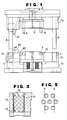
- Fig. 1 is a side elevational view of a metallic matrix with a core side metallic matrix element separated from a cavity side metallic matrix element showing a preferred embodiment of the present invention;
- Fig. 2 is a side elevational view of the metallic matrix of Fig. 1 in an assembled condition;
- Fig. 3 is an enlarged sectional view showing a guide hole in which a bush is fitted;
- Fig. 4 is a perspective view of a slide core of the metallic matrix of Fig. 1 as viewed from the side of a bottom sliding wall of the same; and
- Fig. 5 is a schematic representation illustrating an arrangement of solid lubricant receiving holes.
- Referring first to Figs. 1 and 2, there is shown a metallic matrix for injection molding according to a preferred embodiment of the present invention. The metallic matrix shown includes a cavity side
metallic matrix element 1a and a core sidemetallic matrix element 1b. The cavity sidemetallic matrix element 1a has arecessed nozzle touch 5 formed therein for fitting with a nozzle of an injector not shown from which a molten resin material is injected into thenozzle touch 5. The material injected into thenozzle touch 5 is passed successively through introducingpaths molding section 4 which is formed by themetallic matrix elements metallic matrix element 1a has several guide poles 6 provided thereon for guiding opening and closing movement of themetallic matrix elements metallic matrix element 1b hascorresponding guide holes 7 formed therein for receiving the guide poles 6 of the cavity sidemetallic matrix element 1a. - A
bush 71 is fitted in each of theguide holes 7 of the core sidemetallic matrix element 1b such that the corresponding guide pole 6 of the cavity sidemetallic matrix element 1b may be fitted over the entire sliding face thereof in thebush 71. As seen in Fig. 3, thebush 71 has a plurality of receivingholes 72 formed in a sliding wall thereof in such a positional relationship that end faces thereof may be positioned in a partially overlapping relationship in the direction of sliding movement of the guide pole 6. A solid lubricant A is received in each of the receivingholes 72 of thebush 71. Themetallic matrix element 1b has anangular hole 44 formed therein while the othermetallic matrix element 1a has anangular pin 41 provided thereon, and aslide core 42 is provided on themetallic matrix element 1b. When themetallic matrix element 1a is slidably moved to open or close the metallic matrix elements la and 1b, theangular pin 41 on themetallic matrix element 1a is advanced into or retracted from theangular hole 44 in themetallic matrix element 1b whereupon theslide core 42 moves anundercut core 43 into or out of a cavity of themolding section 4. Theslide core 42 has a large number of receivingholes 73 formed in a slidingbottom wall 45 thereof and also in asliding wall 46 thereof with aslider guide 47 in such a positional relationship that end faces thereof may be positioned in a partially overlapping relationship in the direction of sliding movement of theslide core 42. The solid lubricant A is received also in thereceiving holes 73 in theslide core 42. - The receiving
holes - Since the metallic matrix for injection molding according to the present invention has such a construction as described hereinabove, a high lubricating effect can be assured at a high temperature of the metallic matrix which is exposed to a high temperature by its nature. Besides, a cumbersome operation which is normally required due to appearance of oil cake or aged oil peculiar to oil lubrication can be eliminated, and an efficient metallic matrix can be obtained.
Claims (4)
Applications Claiming Priority (2)
| Application Number | Priority Date | Filing Date | Title |
|---|---|---|---|
| JP63152133A JPH01320121A (en) | 1988-06-22 | 1988-06-22 | Built-in lubrication mold for injection molding |
| JP152133/88 | 1988-06-22 |
Publications (2)
| Publication Number | Publication Date |
|---|---|
| EP0347506A2 true EP0347506A2 (en) | 1989-12-27 |
| EP0347506A3 EP0347506A3 (en) | 1990-11-07 |
Family
ID=15533771
Family Applications (1)
| Application Number | Title | Priority Date | Filing Date |
|---|---|---|---|
| EP19880311117 Withdrawn EP0347506A3 (en) | 1988-06-22 | 1988-11-24 | Self-lubricating metallic matrix for injection molding |
Country Status (6)
| Country | Link |
|---|---|
| US (1) | US4902212A (en) |
| EP (1) | EP0347506A3 (en) |
| JP (1) | JPH01320121A (en) |
| KR (1) | KR910005182B1 (en) |
| AU (1) | AU602618B2 (en) |
| CA (1) | CA1315058C (en) |
Cited By (2)
| Publication number | Priority date | Publication date | Assignee | Title |
|---|---|---|---|---|
| DE202006014168U1 (en) * | 2006-09-12 | 2008-02-14 | Günther Heisskanaltechnik Gmbh | Actuator for valve pins in injection molding devices with needle valve nozzles |
| EP4098422A4 (en) * | 2020-01-31 | 2024-03-27 | Nissei Asb Machine Co Ltd | Mold, blow molding device, and injection molding device |
Families Citing this family (8)
| Publication number | Priority date | Publication date | Assignee | Title |
|---|---|---|---|---|
| US5407344A (en) * | 1993-07-12 | 1995-04-18 | Lake Center Industries, Inc. | Single direction cam for insert molding machine |
| US6358029B1 (en) * | 1998-04-07 | 2002-03-19 | Yuugen Kaisha Nimitekkou | Metal mold and press device |
| KR100592849B1 (en) * | 2004-04-08 | 2006-06-23 | 엘에스전선 주식회사 | Damper system of the injection molding machine |
| US7387505B1 (en) * | 2006-11-24 | 2008-06-17 | Cheng Uei Precision Industry Co., Ltd. | Side-action mechanism and injection mold using the same |
| US20090068301A1 (en) * | 2007-09-07 | 2009-03-12 | Wen-Hua Huang | Protection Structure for an Optical Lens Module |
| DE102012019357B4 (en) * | 2012-10-02 | 2017-05-18 | Meusburger GmbH & Co. KG | Spray or die casting tool with slide guide |
| CN115056447A (en) * | 2022-04-27 | 2022-09-16 | 海天塑机集团有限公司 | Lubricating control method and system for mold closing part of injection molding machine |
| CN115071091B (en) * | 2022-04-29 | 2023-10-17 | 海天塑机集团有限公司 | Lubrication control method and system based on operation mode of injection molding machine |
Citations (4)
| Publication number | Priority date | Publication date | Assignee | Title |
|---|---|---|---|---|
| US1743645A (en) * | 1928-05-14 | 1930-01-14 | Robert H Whiteley | Bearing |
| US4096075A (en) * | 1976-11-18 | 1978-06-20 | Sankyo Oilless Industries, Inc. | Self-lubricated solid materials |
| GB2015258A (en) * | 1978-02-27 | 1979-09-05 | Burroughs Corp | Adjustable magnetic bias field structure for magnetic bubble devices |
| US4668104A (en) * | 1984-12-31 | 1987-05-26 | Hermann Jr Rudolph J | Self-lubricating member with strip pattern |
Family Cites Families (9)
| Publication number | Priority date | Publication date | Assignee | Title |
|---|---|---|---|---|
| US3574658A (en) * | 1967-12-22 | 1971-04-13 | Ball Brothers Res Corp | Dry-lubricated surface and method of producing such surfaces |
| JPS4838667B1 (en) * | 1969-05-16 | 1973-11-19 | ||
| AT362149B (en) * | 1979-03-14 | 1981-04-27 | Faigle Heinz Kg | PLASTIC / PLASTIC PAIRINGS IN TRIBOLOGICAL SYSTEMS |
| GB2051258B (en) * | 1979-06-12 | 1983-12-14 | Sankyo Oilless Kogyo Kk | Self-lubricating member |
| DE3312634A1 (en) * | 1983-04-08 | 1984-10-11 | Dr. Karl Thomae Gmbh, 7950 Biberach | IMPROVED METHOD AND DEVICES FOR POINTING MOLDING TOOLS WITH DROPLETS OF LIQUID OR SUSPENDED LUBRICANTS IN THE PRODUCTION OF FORMS IN THE PHARMACEUTICAL, FOOD OR CATALYST AREA |
| US4515342A (en) * | 1984-04-06 | 1985-05-07 | Borislav Boskovic | Slide retainer |
| JPH0780111B2 (en) * | 1984-12-14 | 1995-08-30 | 出光興産株式会社 | Lubrication method for machine tools |
| JPS6291560A (en) * | 1985-10-18 | 1987-04-27 | Asahi Glass Co Ltd | Lubricating resin composition |
| US4768747A (en) * | 1987-07-31 | 1988-09-06 | Williams John B | Slide clip |
-
1988
- 1988-06-22 JP JP63152133A patent/JPH01320121A/en active Pending
- 1988-11-08 KR KR1019880014662A patent/KR910005182B1/en not_active IP Right Cessation
- 1988-11-22 AU AU25775/88A patent/AU602618B2/en not_active Ceased
- 1988-11-24 CA CA000584019A patent/CA1315058C/en not_active Expired - Fee Related
- 1988-11-24 EP EP19880311117 patent/EP0347506A3/en not_active Withdrawn
- 1988-12-05 US US07/279,766 patent/US4902212A/en not_active Expired - Fee Related
Patent Citations (4)
| Publication number | Priority date | Publication date | Assignee | Title |
|---|---|---|---|---|
| US1743645A (en) * | 1928-05-14 | 1930-01-14 | Robert H Whiteley | Bearing |
| US4096075A (en) * | 1976-11-18 | 1978-06-20 | Sankyo Oilless Industries, Inc. | Self-lubricated solid materials |
| GB2015258A (en) * | 1978-02-27 | 1979-09-05 | Burroughs Corp | Adjustable magnetic bias field structure for magnetic bubble devices |
| US4668104A (en) * | 1984-12-31 | 1987-05-26 | Hermann Jr Rudolph J | Self-lubricating member with strip pattern |
Non-Patent Citations (2)
| Title |
|---|
| MACHINE DESIGN, vol. 58, no. 22, 25th September 1986, pages 58-63, Cleveland, Ohio, US; M. KASAHARA: "Sorting out oilless bearings" * |
| OILES 500, April 1985; J. METALL: "Selbstschmierende Gleitelemente" * |
Cited By (2)
| Publication number | Priority date | Publication date | Assignee | Title |
|---|---|---|---|---|
| DE202006014168U1 (en) * | 2006-09-12 | 2008-02-14 | Günther Heisskanaltechnik Gmbh | Actuator for valve pins in injection molding devices with needle valve nozzles |
| EP4098422A4 (en) * | 2020-01-31 | 2024-03-27 | Nissei Asb Machine Co Ltd | Mold, blow molding device, and injection molding device |
Also Published As
| Publication number | Publication date |
|---|---|
| AU2577588A (en) | 1990-01-04 |
| AU602618B2 (en) | 1990-10-18 |
| EP0347506A3 (en) | 1990-11-07 |
| CA1315058C (en) | 1993-03-30 |
| US4902212A (en) | 1990-02-20 |
| KR910005182B1 (en) | 1991-07-23 |
| KR900000179A (en) | 1990-01-30 |
| JPH01320121A (en) | 1989-12-26 |
Similar Documents
| Publication | Publication Date | Title |
|---|---|---|
| EP0347506A2 (en) | Self-lubricating metallic matrix for injection molding | |
| US4773845A (en) | Toggle-type mold-clamping apparatus | |
| DE19544931A1 (en) | Chain link of an energy chain with additional body | |
| DE4032478A1 (en) | INJECTION MOLDING TOOL | |
| US4889311A (en) | Molding apparatus with improved ejector pin | |
| DE202005004383U1 (en) | Planing guide shot for Gleithobel | |
| DE4421566C1 (en) | Plastic piston mfr. | |
| DE1915394B2 (en) | HORIZONTAL MOLD CLAMPING DEVICE, IN PARTICULAR FOR PLASTIC INJECTION MOLDING MACHINES | |
| DE102005050102B4 (en) | Open-end spinning device with a fiber channel of several channel components | |
| DE3100116A1 (en) | HOLDING DEVICE FOR SENSITIVATED CUTTING TOOLS IN MINING MACHINES | |
| DE19916250A1 (en) | Mold used in gas injection molding system | |
| US4235575A (en) | Device for lubricating the tie rods of an injection molding machine | |
| CN106863708B (en) | Mold and its line position component | |
| DE19915042A1 (en) | Linear motion guide arrangement, e.g. for machine tool, industrial machine or measurement instrument | |
| DE10101054B4 (en) | holding part | |
| DE2839633A1 (en) | LUBRICANT DISTRIBUTION DEVICE | |
| CN211760205U (en) | Double-open type numerical control machine tool isolation door | |
| DE19916290A1 (en) | Mold and ejection system used in conjunction with gas injection | |
| CN215039928U (en) | Self-lubricating ejector pin inside ejection device of injection mold | |
| DE2460433C2 (en) | Ejector device for an injection mold or die casting mold, with a flat ejector | |
| CN212615926U (en) | Short slider with high lubrication degree | |
| PT92076A (en) | Self-lubricating metal die for injection moulding | |
| CN211276217U (en) | Wear-resisting chute mechanism of half mould easy processing | |
| JP2000102953A (en) | Die for injection molding | |
| CN109262909A (en) | Mold four sides slide block mechanism control sequence is advanced and is exited |
Legal Events
| Date | Code | Title | Description |
|---|---|---|---|
| PUAI | Public reference made under article 153(3) epc to a published international application that has entered the european phase |
Free format text: ORIGINAL CODE: 0009012 |
|
| AK | Designated contracting states |
Kind code of ref document: A2 Designated state(s): AT DE ES FR GB IT NL |
|
| PUAL | Search report despatched |
Free format text: ORIGINAL CODE: 0009013 |
|
| AK | Designated contracting states |
Kind code of ref document: A3 Designated state(s): AT DE ES FR GB IT NL |
|
| 17P | Request for examination filed |
Effective date: 19901018 |
|
| 17Q | First examination report despatched |
Effective date: 19910708 |
|
| STAA | Information on the status of an ep patent application or granted ep patent |
Free format text: STATUS: THE APPLICATION IS DEEMED TO BE WITHDRAWN |
|
| 18D | Application deemed to be withdrawn |
Effective date: 19920603 |