EP0347472A1 - Spindle orientation controller - Google Patents
Spindle orientation controller Download PDFInfo
- Publication number
- EP0347472A1 EP0347472A1 EP89900923A EP89900923A EP0347472A1 EP 0347472 A1 EP0347472 A1 EP 0347472A1 EP 89900923 A EP89900923 A EP 89900923A EP 89900923 A EP89900923 A EP 89900923A EP 0347472 A1 EP0347472 A1 EP 0347472A1
- Authority
- EP
- European Patent Office
- Prior art keywords
- velocity
- spindle
- signal
- orientation
- command
- Prior art date
- Legal status (The legal status is an assumption and is not a legal conclusion. Google has not performed a legal analysis and makes no representation as to the accuracy of the status listed.)
- Ceased
Links
Images


Classifications
-
- G—PHYSICS
- G05—CONTROLLING; REGULATING
- G05B—CONTROL OR REGULATING SYSTEMS IN GENERAL; FUNCTIONAL ELEMENTS OF SUCH SYSTEMS; MONITORING OR TESTING ARRANGEMENTS FOR SUCH SYSTEMS OR ELEMENTS
- G05B19/00—Program-control systems
- G05B19/02—Program-control systems electric
- G05B19/18—Numerical control [NC], i.e. automatically operating machines, in particular machine tools, e.g. in a manufacturing environment, so as to execute positioning, movement or co-ordinated operations by means of program data in numerical form
- G05B19/19—Numerical control [NC], i.e. automatically operating machines, in particular machine tools, e.g. in a manufacturing environment, so as to execute positioning, movement or co-ordinated operations by means of program data in numerical form characterised by positioning or contouring control systems, e.g. to control position from one programmed point to another or to control movement along a programmed continuous path
- G05B19/21—Numerical control [NC], i.e. automatically operating machines, in particular machine tools, e.g. in a manufacturing environment, so as to execute positioning, movement or co-ordinated operations by means of program data in numerical form characterised by positioning or contouring control systems, e.g. to control position from one programmed point to another or to control movement along a programmed continuous path using an incremental digital measuring device
- G05B19/23—Numerical control [NC], i.e. automatically operating machines, in particular machine tools, e.g. in a manufacturing environment, so as to execute positioning, movement or co-ordinated operations by means of program data in numerical form characterised by positioning or contouring control systems, e.g. to control position from one programmed point to another or to control movement along a programmed continuous path using an incremental digital measuring device for point-to-point control
- G05B19/231—Numerical control [NC], i.e. automatically operating machines, in particular machine tools, e.g. in a manufacturing environment, so as to execute positioning, movement or co-ordinated operations by means of program data in numerical form characterised by positioning or contouring control systems, e.g. to control position from one programmed point to another or to control movement along a programmed continuous path using an incremental digital measuring device for point-to-point control the positional error is used to control continuously the servomotor according to its magnitude
- G05B19/237—Numerical control [NC], i.e. automatically operating machines, in particular machine tools, e.g. in a manufacturing environment, so as to execute positioning, movement or co-ordinated operations by means of program data in numerical form characterised by positioning or contouring control systems, e.g. to control position from one programmed point to another or to control movement along a programmed continuous path using an incremental digital measuring device for point-to-point control the positional error is used to control continuously the servomotor according to its magnitude with a combination of feedback covered by G05B19/232 - G05B19/235
-
- G—PHYSICS
- G05—CONTROLLING; REGULATING
- G05B—CONTROL OR REGULATING SYSTEMS IN GENERAL; FUNCTIONAL ELEMENTS OF SUCH SYSTEMS; MONITORING OR TESTING ARRANGEMENTS FOR SUCH SYSTEMS OR ELEMENTS
- G05B19/00—Program-control systems
- G05B19/02—Program-control systems electric
- G05B19/18—Numerical control [NC], i.e. automatically operating machines, in particular machine tools, e.g. in a manufacturing environment, so as to execute positioning, movement or co-ordinated operations by means of program data in numerical form
- G05B19/19—Numerical control [NC], i.e. automatically operating machines, in particular machine tools, e.g. in a manufacturing environment, so as to execute positioning, movement or co-ordinated operations by means of program data in numerical form characterised by positioning or contouring control systems, e.g. to control position from one programmed point to another or to control movement along a programmed continuous path
- G05B19/39—Numerical control [NC], i.e. automatically operating machines, in particular machine tools, e.g. in a manufacturing environment, so as to execute positioning, movement or co-ordinated operations by means of program data in numerical form characterised by positioning or contouring control systems, e.g. to control position from one programmed point to another or to control movement along a programmed continuous path using a combination of the means covered by at least two of the preceding groups G05B19/21, G05B19/27 and G05B19/33
-
- G—PHYSICS
- G05—CONTROLLING; REGULATING
- G05B—CONTROL OR REGULATING SYSTEMS IN GENERAL; FUNCTIONAL ELEMENTS OF SUCH SYSTEMS; MONITORING OR TESTING ARRANGEMENTS FOR SUCH SYSTEMS OR ELEMENTS
- G05B2219/00—Program-control systems
- G05B2219/30—Nc systems
- G05B2219/41—Servomotor, servo controller till figures
- G05B2219/41007—Select gain as function of gear ratio
-
- G—PHYSICS
- G05—CONTROLLING; REGULATING
- G05B—CONTROL OR REGULATING SYSTEMS IN GENERAL; FUNCTIONAL ELEMENTS OF SUCH SYSTEMS; MONITORING OR TESTING ARRANGEMENTS FOR SUCH SYSTEMS OR ELEMENTS
- G05B2219/00—Program-control systems
- G05B2219/30—Nc systems
- G05B2219/42—Servomotor, servo controller kind till VSS
- G05B2219/42104—Loop switch, speed loop then position loop, mode switch
-
- G—PHYSICS
- G05—CONTROLLING; REGULATING
- G05B—CONTROL OR REGULATING SYSTEMS IN GENERAL; FUNCTIONAL ELEMENTS OF SUCH SYSTEMS; MONITORING OR TESTING ARRANGEMENTS FOR SUCH SYSTEMS OR ELEMENTS
- G05B2219/00—Program-control systems
- G05B2219/30—Nc systems
- G05B2219/42—Servomotor, servo controller kind till VSS
- G05B2219/42114—Loop mode, dual mode incremental coarse, analog fine
-
- G—PHYSICS
- G05—CONTROLLING; REGULATING
- G05B—CONTROL OR REGULATING SYSTEMS IN GENERAL; FUNCTIONAL ELEMENTS OF SUCH SYSTEMS; MONITORING OR TESTING ARRANGEMENTS FOR SUCH SYSTEMS OR ELEMENTS
- G05B2219/00—Program-control systems
- G05B2219/30—Nc systems
- G05B2219/42—Servomotor, servo controller kind till VSS
- G05B2219/42203—Using a counter and a limit switch
-
- G—PHYSICS
- G05—CONTROLLING; REGULATING
- G05B—CONTROL OR REGULATING SYSTEMS IN GENERAL; FUNCTIONAL ELEMENTS OF SUCH SYSTEMS; MONITORING OR TESTING ARRANGEMENTS FOR SUCH SYSTEMS OR ELEMENTS
- G05B2219/00—Program-control systems
- G05B2219/30—Nc systems
- G05B2219/42—Servomotor, servo controller kind till VSS
- G05B2219/42215—Stop machine in a predetermined position
-
- G—PHYSICS
- G05—CONTROLLING; REGULATING
- G05B—CONTROL OR REGULATING SYSTEMS IN GENERAL; FUNCTIONAL ELEMENTS OF SUCH SYSTEMS; MONITORING OR TESTING ARRANGEMENTS FOR SUCH SYSTEMS OR ELEMENTS
- G05B2219/00—Program-control systems
- G05B2219/30—Nc systems
- G05B2219/43—Speed, acceleration, deceleration control ADC
- G05B2219/43127—As a function of, select reference velocity as function of gear ratio
-
- G—PHYSICS
- G05—CONTROLLING; REGULATING
- G05B—CONTROL OR REGULATING SYSTEMS IN GENERAL; FUNCTIONAL ELEMENTS OF SUCH SYSTEMS; MONITORING OR TESTING ARRANGEMENTS FOR SUCH SYSTEMS OR ELEMENTS
- G05B2219/00—Program-control systems
- G05B2219/30—Nc systems
- G05B2219/43—Speed, acceleration, deceleration control ADC
- G05B2219/43194—Speed steps, switch over as function of position
Definitions
- This invention relates to a spindle orientation control apparatus for controlling a spindle motor to stop the motor at a fixed position.
- spindle orientation In a numerically controlled.(NC) machine tool, it is necessary to stop a spindle at an arbitrary position with high precision in accordance with a particular purpose. For example, to carry out tapping machining at a predetermined rotational angular position on a workpiece by means of a lathe, it is required that a spindle be stopped at the predetermined rotational position (this is referred to as "spindle orientation").
- Fig. 6 is a block diagram illustrating a conventional spindle orientation control apparatus.
- This spindle orientation control apparatus is such that a spindle A is coupled via a gear d to a servomotor M acting as a spindle motor, with spindle orientation control being performed by an NC unit a.
- SW denotes a switch for transmitting a command from the NC unit a to a velocity control circuit b and a position control circuit c in switching fashion
- TG represents a tachogenerator for detecting average velocity AV of the servomotor M
- S designates a magnetic sensor for detecting the rotational position of the spindle.
- this orientation control apparatus When stop-control is performed while detecting the rotating state of the spindle by the magnetic sensor S, the spindle A is subjected to control at a fixed velocity until an orientation command (ORCM) is outputted from the NC unit a to the velocity control circuit b or position control circuit c in accordance with a velocity pattern at the time of orientation control.
- the rotational velocity of the motor is controlled by a velocity command VCMD from the NC unit a when time t 0 arrives, in response to which the velocity declines at a fixed slope.
- the rotational velocity of the servomotor M has dropped to a predetermined velocity, from which moment onward there is a transition to rotation at a fixed velocity based on the commanded orientation velocity.
- the contact of switch SW is changed over so that the connection of NC unit a is changed from the velocity control circuit b to the position control circuit c.
- the spindle A is controlled in accordance with the rotational position signal from the magnetic sensor S from time t 2 onward, so that it is possible to stop the spindle at a target position.
- spindle velocity attains the orientation velocity owing to input of the velocity AV of servomotor M to the position control circuit c, after which a signal indicative of one revolution of the spindle A is detected, based on the orientation command, and fixed position-stop control becomes possible.
- the spindle A can be stopped at the fixed position only upon making at least one revolution after the spindle has attained the orientation velocity.
- the present invention has been devised in order to solve the foregoing problem and its object is to provide a spindle orientation control apparatus in which position is monitored by velocity pulses at orientation time and at other times as well, wherein a spindle can be stopped at a fixed position in a short period of time.
- a spindle orientation control apparatus in which a spindle for which there are extracted a spindle stopping-position proximity (LS) signal and a stopping position determination (MS) signal is coupled via coupling means to a spindle motor and the spindle is controlled to stop at a fixed position based on a velocity command conforming to velocity of the spindle motor, the apparatus comprising setting means for setting position gain of the spindle, arithmetic means for deciding a first orientation velocity conforming to the position gain and a gear ratio of the coupling means, and a second orientation velocity clamped at a level continuous with the MS signal, status sensing means for deciding a predetermined sequence status signal from the second orientation velocity and a velocity pulse fed back as a position pulse, velocity command means for latching the velocity pulse by the sequence status pulse and reducing the velocity command in dependence upon the velocity pulse fed back, and control means for connecting the velocity command to the MS signal level and detecting the LS signal, thereby performing fixed-position stop-
- LS spindle stopping-position
- the spindle orientation control apparatus of the invention is such that position is monitored based on velocity pulses at a velocity less than the first orientation velocity, and a velocity command corresponding to the second orientation velocity is decided after power is introduced, so that the spindle can be stopped at the fixed position in a short period of time.
- Fig. 1 is a block diagram illustrating the simplified construction of the spindle orientation control apparatus. Shown in Fig. 1 are an arithmetic circuit 1 which includes a microcomputer and the like, a spindle motor 2, a velocity detector 3, a spindle 4, a gear or belt 5 connecting the spindle motor to the spindle, a mount 6 for fixing a magnetic body 8 of a magnetic sensor 7, a magnetic sensor head 9, amplifiers 10 - 12, and comparators 13, 14.
- arithmetic circuit 1 which includes a microcomputer and the like, a spindle motor 2, a velocity detector 3, a spindle 4, a gear or belt 5 connecting the spindle motor to the spindle, a mount 6 for fixing a magnetic body 8 of a magnetic sensor 7, a magnetic sensor head 9, amplifiers 10 - 12, and comparators 13, 14.
- a signal detected by the velocity detector 3 is fed into the arithmetic circuit 1 and comparator 13 as a velocity feedback signal, and current supplied to the spindle motor is fed back to the comparator 14 to form a minor loop.
- a stopping-position proximity signal LS and a stopping position decision signal MS enter the arithmetic signal 1 from the magnetic sensor 7.
- the magnetic sensor 7 includes a magnetic body 8 of length L (mm) coupled directly to the spindle mount 6, and a magnetic sensor head 9 arranged at a position a distance H (mm) from the center of the spindle mount 6.
- velocity pulses serve as position pulses and the velocity command VCMD is diminished by an amount corresponding to the feedback pulses.
- the velocity command VCMD is such that a sequence status signal SQ 2 becomes 1 between the orientation velocity VCMOR1 and the second orientation velocity VCMOR2 clamped at a level connected with the MS signal.
- Region (3) is a fixed-velocity control region in which the velocity command VCMD attains a level A, which is the second orientation velocity VCMOR2, where
- Region (4) is a region in which control is performed by a velocity command based on the MS signal.
- the peak value of the MS signal decides the second orientation velocity VCMOR2. In other words, this is normalized to the magnitude of the level A and stops the spindle at time t 3 , at which the MS signal crosses zero.
- control apparatus of the invention for performing spindle orientation control by the orientation command ORCM set as described above, it is possible to stop the spindle at a fixed position in a short period of time by monitoring position, by means of the velocity detection pulses, both at the time of spindle orientation and at other times as well.
- Fig. 5 is a flowchart illustrating the processing procedure of the invention. This flowchart will now be described.
- step Pl a check is performed to determine whether the orientation command OR C M is being outputted. If the decision rendered is NO, the sequence status signal SQ 1 is made 0 at step P2, and the actual velocity TS A and orientation velocity VCMOR1 are compared at step P3.
- step P8 When it is decided at step P3 that the actual velocity TSA is less than the orientation velocity VCMOR1, the sequence status signal SQ 2 is investigated (step P8). If SQ 2 ⁇ 1 holds, a check is performed to determine whether the motor M is rotating (step 9), a check is performed to determine whether the leading edge of the LS signal has been detected (step 10), the sequence status signal SQ 2 is set to 1 (step 11) after edge detection and the program then proceeds to step 14. When the edge is not detected, the program proceeds to step P12.
- step P16 this is a state in which a transition is made to the velocity command VCMOR in the patterns of Figs. 4(c), (d)].
- the spindle orientation control apparatus of the invention is such that velocity pulses for detecting the rotational velocity of a motor are employed as position pulses, a velocity command value is reduced by an amount corresponding to a number of feedback pulses, the command value is clamped at a predetermined level when the velocity command value of the spindle attains the predetermined level, a changeover for making a spindle stop-position decision signal the velocity command value is performed if a spindle stop-position proximity signal is detected when the clamped state prevails, monitoring of position from velocity pulses is performed also at velocities less than an orientation velocity, and a second orientation velocity is decided after the introduction of power, thereby making it possible to stop the spindle at a fixed position in a short period of time.
Landscapes
- Engineering & Computer Science (AREA)
- Human Computer Interaction (AREA)
- Manufacturing & Machinery (AREA)
- Physics & Mathematics (AREA)
- General Physics & Mathematics (AREA)
- Automation & Control Theory (AREA)
- Control Of Position Or Direction (AREA)
- Stopping Of Electric Motors (AREA)
- Automatic Control Of Machine Tools (AREA)
Abstract
Description
- This invention relates to a spindle orientation control apparatus for controlling a spindle motor to stop the motor at a fixed position.
- In a numerically controlled.(NC) machine tool, it is necessary to stop a spindle at an arbitrary position with high precision in accordance with a particular purpose. For example, to carry out tapping machining at a predetermined rotational angular position on a workpiece by means of a lathe, it is required that a spindle be stopped at the predetermined rotational position (this is referred to as "spindle orientation").
- Fig. 6 is a block diagram illustrating a conventional spindle orientation control apparatus. This spindle orientation control apparatus is such that a spindle A is coupled via a gear d to a servomotor M acting as a spindle motor, with spindle orientation control being performed by an NC unit a. In Fig. 6, SW denotes a switch for transmitting a command from the NC unit a to a velocity control circuit b and a position control circuit c in switching fashion, TG represents a tachogenerator for detecting average velocity AV of the servomotor M, and S designates a magnetic sensor for detecting the rotational position of the spindle.
- The operation of this orientation control apparatus will now be described with reference to a characteristic diagram of motor velocity shown in Fig. 7. When stop-control is performed while detecting the rotating state of the spindle by the magnetic sensor S, the spindle A is subjected to control at a fixed velocity until an orientation command (ORCM) is outputted from the NC unit a to the velocity control circuit b or position control circuit c in accordance with a velocity pattern at the time of orientation control. The rotational velocity of the motor is controlled by a velocity command VCMD from the NC unit a when time t0 arrives, in response to which the velocity declines at a fixed slope. At time tl, the rotational velocity of the servomotor M has dropped to a predetermined velocity, from which moment onward there is a transition to rotation at a fixed velocity based on the commanded orientation velocity. At this time the contact of switch SW is changed over so that the connection of NC unit a is changed from the velocity control circuit b to the position control circuit c. As a result, the spindle A is controlled in accordance with the rotational position signal from the magnetic sensor S from time t2 onward, so that it is possible to stop the spindle at a target position.
- In this conventional spindle orientation control apparatus, spindle velocity attains the orientation velocity owing to input of the velocity AV of servomotor M to the position control circuit c, after which a signal indicative of one revolution of the spindle A is detected, based on the orientation command, and fixed position-stop control becomes possible. This means that the spindle A can be stopped at the fixed position only upon making at least one revolution after the spindle has attained the orientation velocity.
- The present invention has been devised in order to solve the foregoing problem and its object is to provide a spindle orientation control apparatus in which position is monitored by velocity pulses at orientation time and at other times as well, wherein a spindle can be stopped at a fixed position in a short period of time.
- In accordance with the invention, there can be provided a spindle orientation control apparatus in which a spindle for which there are extracted a spindle stopping-position proximity (LS) signal and a stopping position determination (MS) signal is coupled via coupling means to a spindle motor and the spindle is controlled to stop at a fixed position based on a velocity command conforming to velocity of the spindle motor, the apparatus comprising setting means for setting position gain of the spindle, arithmetic means for deciding a first orientation velocity conforming to the position gain and a gear ratio of the coupling means, and a second orientation velocity clamped at a level continuous with the MS signal, status sensing means for deciding a predetermined sequence status signal from the second orientation velocity and a velocity pulse fed back as a position pulse, velocity command means for latching the velocity pulse by the sequence status pulse and reducing the velocity command in dependence upon the velocity pulse fed back, and control means for connecting the velocity command to the MS signal level and detecting the LS signal, thereby performing fixed-position stop-control by the MS signal.
- Accordingly, the spindle orientation control apparatus of the invention is such that position is monitored based on velocity pulses at a velocity less than the first orientation velocity, and a velocity command corresponding to the second orientation velocity is decided after power is introduced, so that the spindle can be stopped at the fixed position in a short period of time.
-
- Fig. 1 is a block diagram illustrating the simplified construction of the invention, Fig. 2 is a view of a magnetic sensor arrangement, Fig. 3 is a characteristic diagram, Figs. 4(a) - (e) are explanatory views, Fig. 5 is a flowchart, Fig. 6 is a block diagram of a conventional example, and Fig. 7 is a characteristic diagram.
- An embodiment of the invention will now be described in detail with reference to the drawings.
- Fig. 1 is a block diagram illustrating the simplified construction of the spindle orientation control apparatus. Shown in Fig. 1 are an
arithmetic circuit 1 which includes a microcomputer and the like, aspindle motor 2, avelocity detector 3, aspindle 4, a gear orbelt 5 connecting the spindle motor to the spindle, amount 6 for fixing amagnetic body 8 of amagnetic sensor 7, amagnetic sensor head 9, amplifiers 10 - 12, andcomparators - A signal detected by the
velocity detector 3 is fed into thearithmetic circuit 1 andcomparator 13 as a velocity feedback signal, and current supplied to the spindle motor is fed back to thecomparator 14 to form a minor loop. A stopping-position proximity signal LS and a stopping position decision signal MS enter thearithmetic signal 1 from themagnetic sensor 7. - As shown in Fig. 2, the
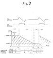
magnetic sensor 7 includes amagnetic body 8 of length L (mm) coupled directly to thespindle mount 6, and amagnetic sensor head 9 arranged at a position a distance H (mm) from the center of thespindle mount 6. - The operation of the apparatus embodying the invention will be described with reference to Fig. 3. First, various factors regarding the invention will be defined.
- (a) Each gear ratio of the spindle (Ag) to the spindle motor (Mg) is Ag:Mg = l:n.
- (b) The detection pulses of the velocity detector are np (pulse/revolution).
- (c) The position gain is Gp sec-1. Here Gp is defined as Gp = V/6, where the amount of motor rotation is 8(rad), when driving the motor in such a manner that a positional offset becomes zero when the motor is rotated at a fixed velocity V (rad/sec).
- In Fig. 3, the velocity command VCMD when control is performed by an orientation command (ORCM) is applied as follows:
- (1) In region (1), VCMOR1 = 60 x Gp x n (rpm), which is decided by position gain and gear ratio, is commanded as velocity. At this time, a sequence status signal SQ1 is decided from the relationship between actual velocity TSA and commanded velocity VCMD. That is, SQ = 1 if TSA > VCMD holds, and SQ1 = 1 if TSA < VCMD holds.
- In region (1) → (2), the value of a velocity pulse counter provided in the arithmetic circuit is latched at the leading edge of the LS signal when the LS signal is generated.
- In region (2), velocity pulses serve as position pulses and the velocity command VCMD is diminished by an amount corresponding to the feedback pulses. In this region, the velocity command VCMD is such that a sequence status signal SQ2 becomes 1 between the orientation velocity VCMOR1 and the second orientation velocity VCMOR2 clamped at a level connected with the MS signal.
- Region (3) is a fixed-velocity control region in which the velocity command VCMD attains a level A, which is the second orientation velocity VCMOR2, where
- A = {(L/2)/(2 x H xπ)} x 60 x Gp = (L x 15 x Gp)/(H x π)
- Region (4) is a region in which control is performed by a velocity command based on the MS signal. Here the peak value of the MS signal decides the second orientation velocity VCMOR2. In other words, this is normalized to the magnitude of the level A and stops the spindle at time t3, at which the MS signal crosses zero. In this region, a sequence status signal SQ4 becomes 1. If the sequence status signal SQl = 0, orientation is not performed irrespective of the other sequence status signals.
- With the control apparatus of the invention for performing spindle orientation control by the orientation command ORCM set as described above, it is possible to stop the spindle at a fixed position in a short period of time by monitoring position, by means of the velocity detection pulses, both at the time of spindle orientation and at other times as well.
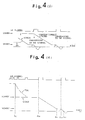
- The foregoing will be described with reference to Figs. 4(a) - e) in conformity with a stop-control pattern, at an initial time t , of a spindle to which an orientation command is applied.
- (a) A case where the spindle is stopped within a range in which the LS signal is generated [Fig. 4(a)]
In this case, the MS signal is outputted as a velocity command, and the spindle is rotated a very small amount and stopped at a predetermined position. - (b) A case where the spindle is stopped outside the range of the LS signal immediately after power is introduced [Fig. 4(b)]
- (1) The orientation velocity decided by the position gain and gear ratio is outputted from time tbs to time tb . o
- (2) When the LS signal is detected at time tb , the velocity command is reduced by the amount of velocity pulses fed back.
- (3) When the level A continuous with the MS signal is detected at time tbl, there is a transition to fixed-velocity control.
- (4) When the next LS signal is detected at time tb2, the MS signal is changed over to the velocity command and the spindle is stopped at a predetermined position at time tb3.
- (c) A case where the spindle is stopped at a position outside the range of the LS signal after having made more than one revolution [Fig. 4(c)]
In this case, unlike case (b), there is outputted a velocity command VCMOR obtained by subtracting the velocity command decrease △VCMD, produced by the velocity feedback pulse, from the orientation velocity VCMOR1. If a transition has already been made to fixed-velocity control of level A when the edge of the first LS signal is detected, then stop-control is immediately applied. - (d) A case where the spindle is rotating at a velocity less than the orientation velocity VCMOR1 outside the range of the LS signal [Fig. 4(d)]
In this case also, as in the case (c), there is outputted a velocity command obtained by subtracting the velocity command decrease △VCMD, produced by the velocity feedback pulse, from the orientation velocity VCMORl. If a transition has already been made to fixed-velocity control of level A when the edge of the first LS signal is detected, then stop-control is immediately applied. - (e) A case where the spindle is rotating at a velocity above the orientation velocity VCMOR1 outside the range of the LS signal [Fig. 4(e)]
- (1) An orientation velocity decided by position gain and gear ratio is outputted at time tes. The LS signal at this time has a narrower pulse interval, as illustrated, because the spindle is rotating at a high velocity.
- (2) When the actual velocity reaches the orientation velocity and the LS signal is detected at time te , the velocity command is reduced by the amount of feedback of the velocity pulses.
- (3) When the level A is detected at time tel, there is a transition to fixed-velocity control.
- (4) When the next LS signal is detected at time te2, the MS signal is changed over as the velocity command and the spindle is stopped at a predetermined position at time te3.
- Fig. 5 is a flowchart illustrating the processing procedure of the invention. This flowchart will now be described.
- First, at step Pl, a check is performed to determine whether the orientation command ORCM is being outputted. If the decision rendered is NO, the sequence status signal SQ1 is made 0 at step P2, and the actual velocity TSA and orientation velocity VCMOR1 are compared at step P3.
- If the decision rendered at step Pl is YES, then the velocity command VCMD is set to the commanded velocity VCMOR at step P4. At this time, if the decision SQ1 = 1 is rendered at step P5 or the actual velocity TS is found to be smaller than the velocity command VCMD at step P6, the program proceeds to step P3, with SQ1 being set to 1 at step P7. If the actual velocity TSA is found to be larger than the velocity command VCMD at
step 6 or larger than the orientation velocity VCMORl atstep 3, then, atstep 12, S2 - S4 are set to 0, the position gain Gp1 is set to Gp, the commanded velocity VCMOR1 is set to the orientation velocity VCMOR, and the program returns to the first step Pl. Gp1 is the value of position gain at the time of orientation. - When it is decided at step P3 that the actual velocity TSA is less than the orientation velocity VCMOR1, the sequence status signal SQ2 is investigated (step P8). If SQ2 ≠ 1 holds, a check is performed to determine whether the motor M is rotating (step 9), a check is performed to determine whether the leading edge of the LS signal has been detected (step 10), the sequence status signal SQ2 is set to 1 (step 11) after edge detection and the program then proceeds to step 14. When the edge is not detected, the program proceeds to step P12.
- If SQ2 = 1 is found to hold at step P8, the sequence status signal SQ3 is checked at step P13. If a NO decision is rendered at this time, then, at step P14, the level A is set as a value obtained by subtracting the acceleration command decrease △VCMD, produced by the velocity feedback pulse, from the orientation velocity VCMOR1; that is, A = VCMOR1 - △VCMD is set as the commanded velocity VCMOR. Thereafter, the commanded velocity VCMOR is compared with the second orientation velocity VCMOR2 (step P15), and the program returns to the first step Pl as long as VCMOR does attain VCMOR2. When the commanded velocity VCMOR becomes smaller than the second orientation velocity VCMOR2, the commanded velocity VCMOR is set to VCMOR2 and the sequence status signal SQ3 is set to 1 (step P16) [this is a state in which a transition is made to the velocity command VCMOR in the patterns of Figs. 4(c), (d)].
- When SQ3 = 1 is verified at step P13, it is checked to see whether SQ4 = 1 holds at step P17. If the decision rendered is NO, it is checked to see whether the LS signal is 1 (whether the spindle position is within the range of the LS signal) at step P18. If the decision rendered is NO, then the second orientation velocity VCMOR2 is set at the velocity command VCMOR at step P19, SQ3, SQ4 are both made 0, and the program returns to the initial step Pl.
- When SQ4 = 1 is verified at step P17, and when the LS signal = 1 is verified at step P18, the velocity command VCMOR is set to a value equal to a predetermined coefficient K times the MS signal and the sequence status signal SQ4 is set to 1 at step P20 [this is a state in which a transition is made from fixed-velocity control to stop-control of level A in the patterns of Figs. 4(c), (d)].
- Though an embodiment of the present invention has been described, the invention it not limited thereto but can be modified in various ways without departing from the scope of the claims.
- The spindle orientation control apparatus of the invention is such that velocity pulses for detecting the rotational velocity of a motor are employed as position pulses, a velocity command value is reduced by an amount corresponding to a number of feedback pulses, the command value is clamped at a predetermined level when the velocity command value of the spindle attains the predetermined level, a changeover for making a spindle stop-position decision signal the velocity command value is performed if a spindle stop-position proximity signal is detected when the clamped state prevails, monitoring of position from velocity pulses is performed also at velocities less than an orientation velocity, and a second orientation velocity is decided after the introduction of power, thereby making it possible to stop the spindle at a fixed position in a short period of time.
The command continues at this level until time t2, which is the leading edge of the LS signal. In this region, the commanded velocity VCMD becomes the second orientation velocity VCMOR2, and a sequence status signal SQ3 becomes 1.
Claims (1)
Applications Claiming Priority (2)
| Application Number | Priority Date | Filing Date | Title |
|---|---|---|---|
| JP62335139A JPH01174283A (en) | 1987-12-28 | 1987-12-28 | Main spindle orientation control device |
| JP335139/87 | 1987-12-28 |
Publications (2)
| Publication Number | Publication Date |
|---|---|
| EP0347472A1 true EP0347472A1 (en) | 1989-12-27 |
| EP0347472A4 EP0347472A4 (en) | 1993-06-09 |
Family
ID=18285199
Family Applications (1)
| Application Number | Title | Priority Date | Filing Date |
|---|---|---|---|
| EP19890900923 Ceased EP0347472A4 (en) | 1987-12-28 | 1988-12-28 | Spindle orientation controller |
Country Status (5)
| Country | Link |
|---|---|
| US (1) | US5030900A (en) |
| EP (1) | EP0347472A4 (en) |
| JP (1) | JPH01174283A (en) |
| KR (1) | KR920008027B1 (en) |
| WO (1) | WO1989006394A1 (en) |
Families Citing this family (14)
| Publication number | Priority date | Publication date | Assignee | Title |
|---|---|---|---|---|
| JPH048423A (en) * | 1990-04-26 | 1992-01-13 | Fanuc Ltd | Tapping method |
| JPH0527845A (en) * | 1991-07-22 | 1993-02-05 | Okuma Mach Works Ltd | Numerical controller having control parameter changing function |
| US5602449A (en) * | 1992-04-13 | 1997-02-11 | Smith & Nephew Endoscopy, Inc. | Motor controlled surgical system and method having positional control |
| US5672945A (en) * | 1992-04-13 | 1997-09-30 | Smith & Nephew Endoscopy, Inc. | Motor controlled surgical system and method having self clearing motor control |
| US5543696A (en) * | 1992-12-10 | 1996-08-06 | Alliedsignal Inc. | Position control for hybrid servomechanisms |
| US6245084B1 (en) | 1998-10-20 | 2001-06-12 | Promex, Inc. | System for controlling a motor driven surgical cutting instrument |
| US6940252B2 (en) * | 2001-01-31 | 2005-09-06 | Canon Kabushiki Kaisha | DC motor control method and apparatus |
| DE10305396A1 (en) * | 2003-02-11 | 2004-08-19 | Dr. Johannes Heidenhain Gmbh | Spindle orientation procedure |
| US7425033B2 (en) | 2003-09-03 | 2008-09-16 | Intier Automotive Closures Inc. | Vehicle sunroof assembly |
| US7560888B2 (en) * | 2005-09-08 | 2009-07-14 | Honeywell International Inc. | Electromechanical actuator including redundant, dissimilar position feedback |
| JP4099503B2 (en) * | 2005-12-19 | 2008-06-11 | ファナック株式会社 | Fixed position stop control device for rotating shaft |
| US8568418B2 (en) | 2011-10-03 | 2013-10-29 | Gyrus Ent L.L.C. | Apparatus for controlling position of rotary surgical instrument |
| US12290274B2 (en) | 2021-05-25 | 2025-05-06 | Arthrex, Inc. | Dynamically controlling a distal window opening in a rotary surgical shaver |
| US12137960B2 (en) | 2021-05-25 | 2024-11-12 | Arthrex, Inc. | Surgical system with adaptive aspiration flow control |
Family Cites Families (5)
| Publication number | Priority date | Publication date | Assignee | Title |
|---|---|---|---|---|
| JPS5697106A (en) * | 1979-12-31 | 1981-08-05 | Fanuc Ltd | Controller for stopping in place for main shaft |
| DE3027581A1 (en) * | 1980-07-21 | 1982-02-25 | Robert Bosch Gmbh, 7000 Stuttgart | Position control of speed regulated NC machine tool - has position and velocity loops to provide high speed positioning |
| JPS5775753A (en) * | 1980-10-30 | 1982-05-12 | Fanuc Ltd | Main shaft rotary position control system |
| JPS60228918A (en) * | 1984-04-26 | 1985-11-14 | Fanuc Ltd | Magnetic sensor |
| JPH0619209A (en) * | 1992-07-02 | 1994-01-28 | Sharp Corp | Electrophotographic developer |
-
1987
- 1987-12-28 JP JP62335139A patent/JPH01174283A/en active Pending
-
1988
- 1988-12-28 US US07/397,444 patent/US5030900A/en not_active Expired - Fee Related
- 1988-12-28 WO PCT/JP1988/001341 patent/WO1989006394A1/en not_active Ceased
- 1988-12-28 KR KR1019890701569A patent/KR920008027B1/en not_active Expired
- 1988-12-28 EP EP19890900923 patent/EP0347472A4/en not_active Ceased
Also Published As
| Publication number | Publication date |
|---|---|
| WO1989006394A1 (en) | 1989-07-13 |
| JPH01174283A (en) | 1989-07-10 |
| US5030900A (en) | 1991-07-09 |
| EP0347472A4 (en) | 1993-06-09 |
| KR920008027B1 (en) | 1992-09-21 |
| KR900700951A (en) | 1990-08-17 |
Similar Documents
| Publication | Publication Date | Title |
|---|---|---|
| EP0347472A1 (en) | Spindle orientation controller | |
| EP0381314A3 (en) | Servo circuit | |
| EP0034927B1 (en) | Spindle orientation control apparatus | |
| EP0294486A1 (en) | Tapping controller | |
| US4379987A (en) | Spindle rotation control system | |
| EP0051453B1 (en) | Spindle orientation control apparatus | |
| EP0245522B1 (en) | Metering device for injection molding machine | |
| JPS63288647A (en) | Tool breakage detecting method | |
| JP2881433B2 (en) | Spindle orientation control device | |
| JPH043237B2 (en) | ||
| JP2844066B2 (en) | Spindle orientation control device | |
| JP3163832B2 (en) | Motor control device | |
| JP2810044B2 (en) | Control device for NC machine | |
| JPH0272419A (en) | Main shaft controller | |
| JP2824649B2 (en) | Spindle controller | |
| JP2001071235A (en) | Numerical control unit | |
| JPS60255097A (en) | Drive controlling method of object to be controlled by stepping motor | |
| JPH06138935A (en) | Numerically controlled machine tool speed control method and apparatus | |
| JPS63242856A (en) | Acceleration/deceleration control device for strip processing line | |
| JPH11143546A (en) | Control method and device for fast moving object | |
| JPH11191011A (en) | Robot control device and control method thereof | |
| JPS6374552A (en) | Orientation control circuit | |
| KR850000311B1 (en) | Spindle exact position control device | |
| JPH03121749A (en) | Spindle specified position stopping system using magnetic sensor | |
| JPH04370807A (en) | Numerical controller |
Legal Events
| Date | Code | Title | Description |
|---|---|---|---|
| PUAI | Public reference made under article 153(3) epc to a published international application that has entered the european phase |
Free format text: ORIGINAL CODE: 0009012 |
|
| 17P | Request for examination filed |
Effective date: 19890825 |
|
| AK | Designated contracting states |
Kind code of ref document: A1 Designated state(s): DE FR GB |
|
| A4 | Supplementary search report drawn up and despatched |
Effective date: 19930420 |
|
| AK | Designated contracting states |
Kind code of ref document: A4 Designated state(s): DE FR GB |
|
| 17Q | First examination report despatched |
Effective date: 19931110 |
|
| GRAG | Despatch of communication of intention to grant |
Free format text: ORIGINAL CODE: EPIDOS AGRA |
|
| STAA | Information on the status of an ep patent application or granted ep patent |
Free format text: STATUS: THE APPLICATION HAS BEEN REFUSED |
|
| 18R | Application refused |
Effective date: 19970530 |