EP0347322B1 - Stable power supply with a low ripple ratio - Google Patents
Stable power supply with a low ripple ratio Download PDFInfo
- Publication number
- EP0347322B1 EP0347322B1 EP89401678A EP89401678A EP0347322B1 EP 0347322 B1 EP0347322 B1 EP 0347322B1 EP 89401678 A EP89401678 A EP 89401678A EP 89401678 A EP89401678 A EP 89401678A EP 0347322 B1 EP0347322 B1 EP 0347322B1
- Authority
- EP
- European Patent Office
- Prior art keywords
- circuit
- voltage
- transformers
- power supply
- rectifier
- Prior art date
- Legal status (The legal status is an assumption and is not a legal conclusion. Google has not performed a legal analysis and makes no representation as to the accuracy of the status listed.)
- Expired - Lifetime
Links
- 230000010363 phase shift Effects 0.000 claims description 6
- 230000001960 triggered effect Effects 0.000 claims description 5
- 238000004804 winding Methods 0.000 claims description 5
- 239000003990 capacitor Substances 0.000 description 14
- 238000001914 filtration Methods 0.000 description 4
- 238000010586 diagram Methods 0.000 description 2
- 238000009434 installation Methods 0.000 description 2
- 230000035939 shock Effects 0.000 description 2
- 230000000903 blocking effect Effects 0.000 description 1
- 230000001276 controlling effect Effects 0.000 description 1
- 239000006185 dispersion Substances 0.000 description 1
- 230000000694 effects Effects 0.000 description 1
- 230000009931 harmful effect Effects 0.000 description 1
- 238000009413 insulation Methods 0.000 description 1
- 238000002955 isolation Methods 0.000 description 1
- 238000004519 manufacturing process Methods 0.000 description 1
- 244000045947 parasite Species 0.000 description 1
- 230000002688 persistence Effects 0.000 description 1
- 230000001105 regulatory effect Effects 0.000 description 1
- 230000000630 rising effect Effects 0.000 description 1
Images
Classifications
-
- H—ELECTRICITY
- H02—GENERATION; CONVERSION OR DISTRIBUTION OF ELECTRIC POWER
- H02M—APPARATUS FOR CONVERSION BETWEEN AC AND AC, BETWEEN AC AND DC, OR BETWEEN DC AND DC, AND FOR USE WITH MAINS OR SIMILAR POWER SUPPLY SYSTEMS; CONVERSION OF DC OR AC INPUT POWER INTO SURGE OUTPUT POWER; CONTROL OR REGULATION THEREOF
- H02M7/00—Conversion of AC power input into DC power output; Conversion of DC power input into AC power output
- H02M7/42—Conversion of DC power input into AC power output without possibility of reversal
- H02M7/44—Conversion of DC power input into AC power output without possibility of reversal by static converters
- H02M7/48—Conversion of DC power input into AC power output without possibility of reversal by static converters using discharge tubes with control electrode or semiconductor devices with control electrode
- H02M7/497—Conversion of DC power input into AC power output without possibility of reversal by static converters using discharge tubes with control electrode or semiconductor devices with control electrode sinusoidal output voltages being obtained by combination of several voltages being out of phase
-
- H—ELECTRICITY
- H02—GENERATION; CONVERSION OR DISTRIBUTION OF ELECTRIC POWER
- H02M—APPARATUS FOR CONVERSION BETWEEN AC AND AC, BETWEEN AC AND DC, OR BETWEEN DC AND DC, AND FOR USE WITH MAINS OR SIMILAR POWER SUPPLY SYSTEMS; CONVERSION OF DC OR AC INPUT POWER INTO SURGE OUTPUT POWER; CONTROL OR REGULATION THEREOF
- H02M3/00—Conversion of DC power input into DC power output
- H02M3/22—Conversion of DC power input into DC power output with intermediate conversion into AC
- H02M3/24—Conversion of DC power input into DC power output with intermediate conversion into AC by static converters
- H02M3/28—Conversion of DC power input into DC power output with intermediate conversion into AC by static converters using discharge tubes with control electrode or semiconductor devices with control electrode to produce the intermediate AC
- H02M3/305—Conversion of DC power input into DC power output with intermediate conversion into AC by static converters using discharge tubes with control electrode or semiconductor devices with control electrode to produce the intermediate AC using devices of a thyratron or thyristor type requiring extinguishing means
- H02M3/315—Conversion of DC power input into DC power output with intermediate conversion into AC by static converters using discharge tubes with control electrode or semiconductor devices with control electrode to produce the intermediate AC using devices of a thyratron or thyristor type requiring extinguishing means using semiconductor devices only
- H02M3/3155—Conversion of DC power input into DC power output with intermediate conversion into AC by static converters using discharge tubes with control electrode or semiconductor devices with control electrode to produce the intermediate AC using devices of a thyratron or thyristor type requiring extinguishing means using semiconductor devices only with automatic control of the output voltage or current
-
- H—ELECTRICITY
- H05—ELECTRIC TECHNIQUES NOT OTHERWISE PROVIDED FOR
- H05G—X-RAY TECHNIQUE
- H05G1/00—X-ray apparatus involving X-ray tubes; Circuits therefor
- H05G1/08—Electrical details
- H05G1/26—Measuring, controlling or protecting
- H05G1/30—Controlling
- H05G1/32—Supply voltage of the X-ray apparatus or tube
Definitions
- the subject of the present invention is a stabilized power supply with a reduced ripple rate, usable in particular in the medical field for electrically supplying X-ray tubes. It can nevertheless be applied to other fields where the need for large powers is encountered.
- electric of the order of one hundred kilowatts (KW) and at very high voltages, for example of the order of 100 kilovolts (KV). It mainly relates to voltage rise supplies, of the continuous continuous type, provided with an inverter.
- a DC-type voltage rise supply generally comprises a first rectifier connectable to an electrical distribution network.
- the rectified and filtered voltage delivered by this rectifier is introduced into a variable frequency inverter which delivers a wavy signal.
- the rippled signal is then applied to a step-up transformer, itself in connection with a second rectifier to produce a rectified high voltage.
- a rectified high voltage can for example be used to control an X-ray tube by providing the necessary potential difference between the cathode and the anode of this tube.
- the regulation of the high voltage delivered is generally obtained by varying the ripple frequency of the inverter, so as to act on its power transfer function as a function of the frequency.
- inverters in DC-type voltage rise power supplies
- the reinjection into the electrical network of reactive energy due to the switching in the inverter is simply doubled, tripled, multiplied by n, when the power thus produced doubles, triples, or is multiplied n times.
- it is necessary to place in the filter circuit of the first rectifier very important filters, therefore very bulky and very expensive. These filters then become all the more expensive as the power is increased.
- Such power supplies are for example described in document WO 86/04749. However, we find there both the industrialization problems and the switching problems mentioned.
- the object of the invention is to remedy these drawbacks by recommending a solution which, at multiple power, borrows exactly the already tried industrial solutions, including the ripple rate of the high voltage across the load, and whose energy reactive feed back into the network are significantly reduced. In practice, a reduction is obtained in a ratio 4.
- the principle of the invention is based on the use of two, three, n identical inverters connected in parallel to the output of the first rectifier, and the triggering of which is out of phase with the relative to each other, in phase quadrature, with a 2 ⁇ / 3 phase shift, with a 2 ⁇ / n phase shift. We can then show that each inverter can provide a fraction P / n of the total power P to be transmitted.
- the structure of a high-voltage block must also ensure perfect balancing between a positive and a negative channel. As it is unlikely that, despite all the precautions taken, the 2 or n inverters thus put into service have equal transfer characteristics, in an improvement we share the contribution of each of these inverters to the positive path of a on the one hand and the negative path on the other. In this improvement, the voltage elevation circuit at the output of the ripple circuit is then a little more complex in its connection to allow, with the use of already proven step-up transformers, balancing between the channels. This balancing is independent of the characteristics of the inverters, and, for each inverter when they are two-wave, between one wave and the other.
- the subject of the invention is therefore a stabilized power supply with a reduced ripple rate according to claim 1 and 2.
- the inverters are of the double-alternation type, and the phase shifts are therefore equal to ⁇ / n.
- the invention relates to a stabilized power supply with a reduced ripple rate according to claim 2.
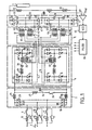
- FIG. 1 shows a stabilized power supply with a reduced ripple rate according to the invention.
- This is in particular intended to supply an X-ray tube 1 usable in a medical application.
- This supply essentially comprises a first rectifier 2 connected to an electrical network 3.
- a ripple circuit 4 makes it possible to ripple a rectified and filtered direct voltage delivered by the first rectifier 2.
- a voltage rise circuit 5 raises the voltage of the signal delivered by the ripple circuit.
- the circuit 5 is connected to a second rectifier 6 intended to produce a high direct voltage from an alternating high voltage delivered by the booster circuit 5.
- the circuit 4 comprises the inverters 7 and 8 respectively.
- these inverters 7 and 8 are of the bi-alternation type and each comprise 2 sets of switches for passing the current alternately in one direction and then in another, in a resonant circuit.
- the operation of the power supply according to the invention is as follows.
- a set of switches 9 to 11 is switched to allow connection of the rectifier 2 to the electrical network 3 by means of resistors in series respectively 12 to 14.
- resistors 12 to 14 are justified by the high power available nature of the power supply to be produced and by the concern to limit the inrush current at ignition in the electrical network.
- Resistors 12 to 14 are only used for precharging the capacitors of the downstream filter. They are only used when the converters are energized, which in turn ensure the rise of high voltage.
- Resistors 12 to 14 play, with the filtering capacities of rectifier 2, a role of low-pass circuit: the starting current does not increase too suddenly.
- the alternating signal delivered by the network 3 is thus applied to the input of a conventional rectifier 2 with diodes 18 to 23.
- the diode rectifier supplies a rectified voltage in a filter cell essentially comprising a filtering capacitor 24 and two shock inductors 25 and 26.
- the capacitor 24 is connected in series between the inductors 25 and 26, the whole is connected in parallel to the diode rectifier.
- a voltage thus rectified and filtered is then available across the capacitor 24.
- a resistor 27 in series with a switch 28 is also placed in parallel on the capacitor 24.
- the ripple circuit comprises n inverters, and in the example a preferred solution will be described with two inverters 7 and 8.
- Each inverter is connected, at its input, in parallel with the output of the first rectifier 2.
- the two inverters are similar.
- the inverter 7 comprises two sets of thyristors respectively T1 T4 and T3 T respectivement. Each set of thyristors is connected in series on either side of a resonant circuit comprising an inductor 29, a capacitor 30 and a primary winding 31 of a transformer 32.
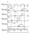
- this inverter is as follows, see Figures 2a to 2c.
- the triggers of the thyristors T1 and T4 are triggered by an order issued by a pilot circuit 33.
- the current then passes through the thyristor T1, in the inductor 29, in the capacitor 30, and in the primary of the transformer 31, to close by thyristor T4 on the output of rectifier 2.
- a positive alternation 34 then arises in the resonant circuit 29 to 31. This alternation gives rise by resonance to a negative reaction alternation 35.
- the current of the reaction alternation 35 is fed back into rectifier 2 via diodes D4 and D1 respectively in parallel on the thyristors T4 and T1.
- the diodes D1 and D4 which allow the passage of the alternation of reaction allow the blocking of the thyristors T1 and T4 until their next triggering.
- the pilot circuit 33 triggers the play of the thyristors T3 and T2 also tending to pass a charge current, but in the opposite direction , in the resonant circuit 29 to 31.
- the thyristors T3 and T2 then give rise to a negative alternation 36 which combines with the alternation 35.
- the alternation 36 gives in the same way as the alternation 34 birth to an alternation of reaction 37.
- the inverter 8 is comparable in all respects to the inverter 7 except that the triggering of its thyristors T5 T8 or T7 T6 is caused in phase quadrature, at times t ⁇ / 2 or t 3 ⁇ / 2 , with respect to at the instants at which the thyristors T1 T4 and T3 T2 are triggered. It follows that the secondary 39 of the transformer 40 of the resonant circuit of the inverter 8 delivers a signal, also sinusoidal, but phase-shifted in quadrature with respect to the signal delivered by secondary 38. We can easily generalize in the case where there are n inverters. In this case the signals delivered by these inverters would be phase-shifted by 2 ⁇ / n, or more exactly by ⁇ / n with, as here, full-wave inverters.
- the signals available on the secondary 38 and 39 are then sent in a booster circuit 5 which, according to a variant, comprises two transformers 41 and 42.
- the two primary respectively 43 and 44 of these transformers 41 and 42 are connected to the secondary, respectively 38 and 39.
- the secondaries 45 and 46 respectively of transformers 41 and 42 are in series with each other and supply a second diode rectifier circuit 47 to 50 of the same type as the first rectifier 2.
- This second rectifier is connected in parallel with two capacitors in series 51 and 52. To balance the assembly, the midpoint of the capacitors 51 and 52 is even connected to the midpoint of the secondaries 45 and 46.
- Other variants are possible.
- this combination of the signals in phase quadrature in two transformers 41, 42 with secondary in series, or in a single transformer with n primary has the effect of delivering a rectified signal with n times more peaks than if there were only one inverter.
- FIG. 2f shows comparatively the undulations 53 obtained after rectification of a signal according to the invention, and the less frequent undulations 54, but at the same time much larger when there is only one inverter.
- the reactive currents compensate each other, which further improves performance.
- the invention naturally has the advantage of using two similar inverters twice, that is to say having successfully undergone a previous industrialization test. Ultimately, the definition of a stabilized power supply with a low ripple rate but at a higher power is thus greatly facilitated.
- the inverters 7 and 8 are not strictly identical. To remedy this drawback, it is recommended to duplicate the transformers such as 41 and 42 in the booster circuit. Two other (n others) 55 and 56 are then mounted, the primaries of which are connected in parallel with the primaries of the transformers 41 and 42 and whose secondary 57 and 58 are connected in series with each other. These secondary 57 and 58 are also connected to another second rectifier circuit, identical to circuit 48-52.
- This second identical rectifier comprises in particular two capacitors in series 59 and 60 at output. We can consider that in parallel with the capacitors 51 and 52 we have the positive channel, and that in parallel with the capacitors 59 and 60 we have a negative channel. It is then possible, by connecting the capacitors 52 and 59 in series, to have a midpoint connectable to ground. In this way, the difficulties of electrical isolation in very high voltage use are reduced. In practice, the insulation constraints are then divided by 2.
- a resistance divider bridge 61 and 62 is connected, the midpoint of which is connected to a comparator 63.
- the comparator 63 also receives a reference voltage V on a comparison input. ref .
- the error signal delivered by the comparator 63 is introduced in a known manner into a voltage frequency converter 64 (VCO) which outputs a square signal, of duty cycle 1, in the pilot circuit 33.
- VCO voltage frequency converter
- FIG. 2a changes so as to keep the phase shift in quadrature of attack of the inverters 7 and 8.
- a duty cycle of 1 corresponds to a pulse signal whose pulse duration is equal to the duration during which the pulse is absent.
- the frequency of the voltage-frequency converter 64 is even twice (or n times) that of the resonance frequency of the inverters. It then suffices to control the triggers of the thyristors of an inverter by the rising edges of the pulse, and the triggers of the thyristors of the other inverter by the falling edges of these pulses. Because the frequency is double from one pulse to another, it is in each inverter, a thyristor set or the other which is triggered. Logic circuits contained in the pilot circuit 33 for carrying out this operation are within the reach of those skilled in the art.
Landscapes
- Engineering & Computer Science (AREA)
- Power Engineering (AREA)
- Health & Medical Sciences (AREA)
- General Health & Medical Sciences (AREA)
- Toxicology (AREA)
- Dc-Dc Converters (AREA)
- Rectifiers (AREA)
- X-Ray Techniques (AREA)
Description
La présente invention a pour objet une alimentation stabilisée à taux d'ondulation réduit, utilisable notamment dans le domaine médical pour alimenter électriquement des tubes à rayons X. Elle peut néanmoins s'appliquer à d'autres domaines où on rencontre le besoin de grandes puissances électriques, de l'ordre de la centaine de kilowatts (KW) et à des très hautes tensions, par exemple de l'ordre de 100 kilovolts (KV). Elle concerne principalement des alimentations à élévation de tension, de type continu continu, munies d'un onduleur.The subject of the present invention is a stabilized power supply with a reduced ripple rate, usable in particular in the medical field for electrically supplying X-ray tubes. It can nevertheless be applied to other fields where the need for large powers is encountered. electric, of the order of one hundred kilowatts (KW) and at very high voltages, for example of the order of 100 kilovolts (KV). It mainly relates to voltage rise supplies, of the continuous continuous type, provided with an inverter.
Une alimentation à élévation de tension de type continu-continu comporte généralement un premier redresseur connectable à un réseau de distribution électrique. La tension redressée et filtrée délivrée par ce redresseur est introduite dans un onduleur à fréquence variable qui délivre un signal ondulé. Le signal ondulé est ensuite appliqué à un transformateur élévateur, lui-même en relation avec un deuxième redresseur pour produire une haute tension redressée. Une telle haute tension redressée est par exemple utilisable pour commander un tube à rayons X en fournissant la différence de potentiel nécessaire entre la cathode et l'anode de ce tube. La régulation de la haute tension délivrée est généralement obtenue en faisant varier la fréquence d'ondulation de l'onduleur, de manière à agir sur sa fonction de transfert en puissance en fonction de la fréquence. Malgré toutes les précautions prises, notamment un choix de cellules de filtrage à forte capacité dans le deuxième redresseur, ou d'une fréquence élevée d'ondulation de l'onduleur, on note la persistance, pendant l'utilisation, d'ondulations de la haute tension délivrée. La fréquence de ces ondulations suit la fréquence de l'onduleur. Ces ondulations de la haute tension délivrée sont par ailleurs d'autant plus sensibles que la puissance susceptible d'être consommée par le tube est forte. Le problème se pose donc plus particulièrement à grande puissance.A DC-type voltage rise supply generally comprises a first rectifier connectable to an electrical distribution network. The rectified and filtered voltage delivered by this rectifier is introduced into a variable frequency inverter which delivers a wavy signal. The rippled signal is then applied to a step-up transformer, itself in connection with a second rectifier to produce a rectified high voltage. Such a rectified high voltage can for example be used to control an X-ray tube by providing the necessary potential difference between the cathode and the anode of this tube. The regulation of the high voltage delivered is generally obtained by varying the ripple frequency of the inverter, so as to act on its power transfer function as a function of the frequency. Despite all the precautions taken, in particular a choice of high capacity filter cells in the second rectifier, or a high frequency of undulation of the inverter, the persistence, during use, of undulations of the high voltage delivered is noted. The frequency of these ripples follows the frequency of the inverter. These undulations of the high voltage delivered are moreover all the more sensitive the higher the power likely to be consumed by the tube. The problem therefore arises more particularly at high power.
Un tel problème se pose par exemple, lorsque disposant d'une alimentation continu-continu de ce type fonctionnant à une puissance donnée, par exemple 50 KW, on désire industrialiser une nouvelle alimentation susceptible de passer le double, le triple, voire n fois la puissance de cette alimentation existante. La solution consistant à développer une nouvelle alimentation dont les caractéristiques de tous les composants seraient doublées, triplées, multipliées par n, n'est pas industriellement praticable car la dispersion des caractéristiques des composants électroniques utilisés est telle que de multiples problèmes de réalisation surviennent. Ils ont pour résultat que cette démarche à priori simple ne peut pas trouver facilement une solution. De longues et coûteuses études doivent être menées dans ce but.Such a problem arises for example, when having a continuous-continuous supply of this type operating at a given power, for example 50 KW, it is desired to industrialize a new supply capable of passing double, triple, or even n times the power of this existing power supply. The solution consisting in developing a new power supply whose characteristics of all the components would be doubled, tripled, multiplied by n, is not industrially practicable since the dispersion of the characteristics of the electronic components used is such that multiple production problems arise. As a result, this apparently simple approach cannot easily find a solution. Long and costly studies must be carried out for this purpose.
En outre, l'utilisation d'onduleurs, dans des alimentations à élévation de tension de type continu-continu, n'est pas sans effets néfastes sur le réseau électrique. En particulier, la réinjection sur le réseau électrique d'énergie réactive due à la commutation dans l'onduleur est tout simplement doublée, triplée, multipliée par n, lorsque la puissance ainsi produite double, triple, ou est multipliée n fois. Pour éviter cette réinjection, il est nécessaire de mettre en place dans le circuit de filtrage du premier redresseur des filtres très importants, donc très volumineux et très chers. Ces filtres deviennent alors d'autant plus chers que la puissance est augmentée. De telles alimentations sont par exemple décrites dans le document WO 86/04749. On y recontre cependant à la fois les problèmes d'industrialisation et les problèmes de commutation évoqués.In addition, the use of inverters, in DC-type voltage rise power supplies, is not without harmful effects on the electrical network. In particular, the reinjection into the electrical network of reactive energy due to the switching in the inverter is simply doubled, tripled, multiplied by n, when the power thus produced doubles, triples, or is multiplied n times. To avoid this reinjection, it is necessary to place in the filter circuit of the first rectifier very important filters, therefore very bulky and very expensive. These filters then become all the more expensive as the power is increased. Such power supplies are for example described in document WO 86/04749. However, we find there both the industrialization problems and the switching problems mentioned.
L'invention a pour objet de remédier à ces inconvénients en préconisant une solution qui, à puissance multiple, emprunte exactement les solutions industrielles déjà éprouvées, dont le taux d'ondulation de la haute tension aux bornes de la charge, et dont l'énergie réactive réinjectée sur le réseau sont considérablement réduites. En pratique on obtient une réduction dans un rapport 4. Le principe de l'invention repose sur l'utilisation de deux, de trois, de n onduleurs identiques branchés en parallèle à la sortie du premier redresseur, et dont le déclenchement est déphasé de l'un par rapport à l'autre, en quadrature de phase, avec un déphasage 2π/3, avec un déphasage 2π/n. On peut alors montrer que chaque onduleur peut fournir une fraction P/n de la puissance totale P à transmettre.The object of the invention is to remedy these drawbacks by recommending a solution which, at multiple power, borrows exactly the already tried industrial solutions, including the ripple rate of the high voltage across the load, and whose energy reactive feed back into the network are significantly reduced. In practice, a reduction is obtained in a ratio 4. The principle of the invention is based on the use of two, three, n identical inverters connected in parallel to the output of the first rectifier, and the triggering of which is out of phase with the relative to each other, in phase quadrature, with a 2π / 3 phase shift, with a 2π / n phase shift. We can then show that each inverter can provide a fraction P / n of the total power P to be transmitted.
Les caractéristiques des composants passifs et actifs utilisables, compte tenu des fréquences de fonctionnement, sont alors plus facilement maîtrisées si elles ne sont pas déjà connues. Il devient notamment possible, avec de tels composants plus petits, de travailler à des fréquences d'ondulation elles-mêmes plus élevées. Ainsi, dans un exemple préféré, en utilisant deux onduleurs bialternances déphasés en quadrature, on obtient aux bornes du tube à rayons X une ondulation équivalente à un redressement 4 crêtes (l'ondulation sur la charge est 4 fois la fréquence de l'onduleur). On a donc pour une fréquence propre de fonctionnement d'un onduleur donné, une ondulation haute tension réduite au moins de moitié par rapport à un générateur comportant un seul onduleur travaillant à la même fréquence propre. En outre, dans ce type de fonctionnement le courant réactif transitant par le filtre du premier redresseur est réduit dans un rapport 4 pour la puissance nominale de l'appareil. Là encore on gagne d'une manière considérable sur le dimensionnement des capacités de filtrage.The characteristics of the passive and active components that can be used, taking into account the operating frequencies, are then more easily mastered if they are not already known. In particular, it becomes possible, with such smaller components, to work at higher ripple frequencies. Thus, in a preferred example, by using two dual-phase inverters phase shifted in quadrature, one obtains at the terminals of the X-ray tube an undulation equivalent to a 4 peak rectification (the ripple on the load is 4 times the frequency of the inverter). There is therefore, for a natural operating frequency of a given inverter, a high voltage ripple reduced by at least half compared to a generator comprising a single inverter working at the same natural frequency. In addition, in this type of operation the reactive current flowing through the filter of the first rectifier is reduced in a ratio 4 for the nominal power of the device. Here again, there is a considerable gain in the dimensioning of the filtering capacities.
La structure d'un bloc haute tension doit en outre assurer un équilibrage parfait entre une voie positive et une voie négative. Comme il est peu probable que, malgré toutes les précautions prises, les 2, ou les n onduleurs ainsi mis en service aient des caractéristiques de transfert égales, dans un perfectionnement on partage la contribution de chacun de ces onduleurs à la voie positive d'une part et à la voie négative d'autre part. Dans ce perfectionnement le circuit d'élévation de tension en sortie du circuit d'ondulation est alors un peu plus complexe dans sa connexion pour permettre, avec l'utilisation de transformateurs élévateurs déjà éprouvés, un équilibrage entre les voies. Cet équilibrage est indépendant des caractéristiques des onduleurs, et, pour chaque onduleur quand ils sont bi-alternance, entre une alternance et l'autre.The structure of a high-voltage block must also ensure perfect balancing between a positive and a negative channel. As it is unlikely that, despite all the precautions taken, the 2 or n inverters thus put into service have equal transfer characteristics, in an improvement we share the contribution of each of these inverters to the positive path of a on the one hand and the negative path on the other. In this improvement, the voltage elevation circuit at the output of the ripple circuit is then a little more complex in its connection to allow, with the use of already proven step-up transformers, balancing between the channels. This balancing is independent of the characteristics of the inverters, and, for each inverter when they are two-wave, between one wave and the other.
L'invention a donc pour objet une alimentation stabilisée à taux d'ondulation réduit conforme à la revendication 1 et 2. Dans un perfectionnement les onduleurs sont de type double alternance, et les déphasages valent en conséquence π/n. Pour remédier aux problèmes de commutation et de réinjection de parasites, l'invention a pour objet une alimentation stabilisée à taux d'ondulation réduit conforme à la revendication 2.The subject of the invention is therefore a stabilized power supply with a reduced ripple rate according to
L'invention sera mieux comprise à la lecture de la description qui suit et à l'examen des figures qui l'accompagnent. Celles ci ne sont données qu'à titre indicatif et nullement limitatif de l'invention. Les figures montrent:
- ― figure 1: le schéma de principe d'une alimentation stabilisée selon l'invention
- ― figures 2a à 2f: des diagrammes temporels de signaux de commande intervenant dans le pilotage de l'alimentation selon l'invention.
- - Figure 1: the block diagram of a stabilized power supply according to the invention
- - Figures 2a to 2f: time diagrams of control signals involved in controlling the power supply according to the invention.
La figure 1 montre une alimentation stabilisée à taux d'ondulation réduit selon l'invention. Celle-ci est notamment destinée à alimenter un tube à rayons X 1 utilisable dans une application médicale. Cette alimentation comporte essentiellement un premier redresseur 2 connecté à un réseau électrique 3. Un circuit d'ondulation 4 permet de faire onduler une tension continue redressée et filtrée délivrée par le premier redresseur 2. Un circuit d'élévation de tension 5 élève la tension du signal délivré par le circuit d'ondulation. Le circuit 5 est connecté à un deuxième redresseur 6 destiné à produire une haute tension continue à partir d'une haute tension alternative délivrée par le circuit élévateur 5. Une caractéristique essentielle de l'invention réside dans le fait que le circuit pour faire onduler le signal délivré par le premier redresseur comporte n onduleurs, ici n = 2. Ainsi, le circuit 4 comporte les onduleurs 7 et 8 respectivement. Dans l'exemple représenté ces onduleurs 7 et 8 sont de type bi-alternance et comportent chacun 2 jeux d'interrupteurs pour faire passer le courant alternativement dans un sens puis dans un autre, dans un circuit résonnant.FIG. 1 shows a stabilized power supply with a reduced ripple rate according to the invention. This is in particular intended to supply an X-ray tube 1 usable in a medical application. This supply essentially comprises a
Le fonctionnement de l'alimentation selon l'invention est le suivant. Au moment de la mise sous tension de l'installation un jeu d'interrupteurs 9 à 11 est commuté pour permettre le raccordement du redresseur 2 au réseau électrique 3 par l'intermédiaire de résistances en série respectivement 12 à 14. La présence des résistances 12 à 14 est justifiée par le caractère grande puissance disponible de l'alimentation à réaliser et par le souci de limiter le courant d'appel à l'amorçage dans le réseau électrique. Les résistances 12 à 14 ne servent qu'à la précharge des condensateurs du filtre en aval. Elles ne servent que lors de la mise sous tension des convertisseurs qui, eux assurent la montée de la haute tension. Les résistances 12 à 14 jouent, avec les capacités de filtrage du redresseur 2, un rôle de circuit passe-bas: le courant d'amorçage ne croît pas trop brutalement. Lorsque cet amorçage est suffisant un deuxième jeu 15 à 17 d'interrupteurs en parallèle avec les résistances 12 à 14 en série avec les interrupteurs respectivement 9 à 11, est fermé de manière à éliminer ultérieurement les pertes énergétiques dans les résistances 12 à 14. Ce temps d'amorçage, ou aussi bien temps de montée, est de l'ordre de quelques millisecondes.The operation of the power supply according to the invention is as follows. When the installation is energized, a set of
Le signal alternatif délivré par le réseau 3 est ainsi appliqué à l'entrée d'un redresseur 2 classique à diodes 18 à 23. Le redresseur à diodes débite une tension redressée dans une cellule de filtrage comportant essentiellement un condensateur de filtrage 24 et deux inductances de choc 25 et 26. Le condensateur 24 est branché en série entre les inductances 25 et 26, le tout est branché en parallèle sur le redresseur à diodes. Une tension ainsi redressée et filtrée est alors disponible aux bornes du condensateur 24. Une résistance 27 en série avec un interrupteur 28 est également placée en parallèle sur le condensateur 24. Au moment de la coupure de l'alimentation électrique de l'installation, la fermeture de l'interrupteur 28 (après réouverture des interrupteurs 9 à 11 et 15 à 17) permet de décharger rapidement le condensateur 24 dans la résistance 27, de manière à ne pas avoir à attendre trop longtemps une décharge par courant de fuite de la capacité 24 à travers les diodes 19 à 22.The alternating signal delivered by the network 3 is thus applied to the input of a
Selon l'invention, le circuit d'ondulation comporte n onduleurs, et dans l'exemple on décrira une solution préférée avec deux onduleurs 7 et 8. Chaque onduleur est relié, à son entrée, en parallèle avec la sortie du premier redresseur 2. Les deux onduleurs sont semblables. Par exemple l'onduleur 7 comporte deux jeux de thyristors respectivement T₁ T₄ et T₃ T₂. Chaque jeu de thyristors est branché en série de part et d'autre d'un circuit résonnant comportant une inductance 29, un condensateur 30 et un enroulement primaire 31 d'un transformateur 32.According to the invention, the ripple circuit comprises n inverters, and in the example a preferred solution will be described with two inverters 7 and 8. Each inverter is connected, at its input, in parallel with the output of the
Le fonctionnement de cet onduleur est le suivant, confer figures 2a à 2c. A un instant t = 0 les gâchettes des thyristors T₁ et T₄ sont déclenchées par un ordre émis par un circuit pilote 33. Le courant passe alors dans le thyristor T₁, dans l'inductance 29, dans la capacité 30, et dans le primaire du transformateur 31, pour se refermer par le thyristor T₄ sur la sortie du redresseur 2. Une alternance positive 34 naît alors dans le circuit résonnant 29 à 31. Cette alternance donne par résonance naissance à une alternance négative de réaction 35. Le courant de l'alternance de réaction 35 est réinjecté dans le redresseur 2 par l'intermédiaire des diodes respectivement D₄ et D₁ en parallèle sur les thyristors T₄ et T₁. Les diodes D₁ et D₄ qui autorisent le passage de l'alternance de réaction permettent le blocage des thyristors T₁ et T₄ jusqu'à leur prochain déclenchement. A un instant tπ (fig 2c) se produisant très peu après le début de l'alternance réactive 35, le circuit pilote 33 déclenche le jeu des thyristors T₃ et T₂ tendant eux aussi à faire passer un courant de charge, mais en sens inverse, dans le circuit résonnant 29 à 31. Les thyristors T₃ et T₂ donnent alors naissance à une alternance négative 36 qui se combine avec l'alternance 35. L'alternance 36 donne de la même façon que l'alternance 34 naissance à une alternance de réaction 37. Il en résulte que le courant qui passe dans le circuit oscillant 29 à 31 est alors sensiblement sinusoidal et que ce courant peut alors être élevé dans le transformateur 32 pour être disponible sur le secondaire 38 de ce transformateur 32. Au bout d'une durée t2π (fig 2b), le phénomène décrit se reproduit sous le pilotage du circuit 33.The operation of this inverter is as follows, see Figures 2a to 2c. At an instant t = 0 the triggers of the thyristors T₁ and T₄ are triggered by an order issued by a
L'onduleur 8 est en tous points comparable à l'onduleur 7 à cela près que le déclenchement de ses thyristors T₅ T₈ ou T₇ T₆ est provoqué en quadrature de phase, à des instants tπ/2 ou t3π/2, par rapport aux instants où sont provoqués les déclenchements des thyristors T₁ T₄ et T₃ T₂. Il en résulte que le secondaire 39 du transformateur 40 du circuit résonnant de l'onduleur 8 délivre un signal, lui aussi sinusoidal, mais déphasé en quadrature par rapport au signal délivré par le secondaire 38. On pourra facilement généraliser dans le cas où il y aurait n onduleurs. Dans ce cas les signaux délivrés par ces onduleurs seraient déphasés de 2π/n, ou plus exactement de π/n avec comme ici des onduleurs bi-alternances.The inverter 8 is comparable in all respects to the inverter 7 except that the triggering of its thyristors T₅ T₈ or T₇ T₆ is caused in phase quadrature, at times t π / 2 or t 3π / 2 , with respect to at the instants at which the thyristors T₁ T₄ and T₃ T₂ are triggered. It follows that the secondary 39 of the
Les signaux disponibles sur les secondaires 38 et 39 sont ensuite envoyés dans un circuit élévateur 5 qui comportent selon une variante, deux transformateurs 41 et 42. Les deux primaires respectivement 43 et 44 de ces transformateurs 41 et 42 sont reliés aux secondaires, respectivement 38 et 39. Les secondaires respectivement 45 et 46 des transformateurs 41 et 42 sont en série l'un avec l'autre et alimentent un deuxième circuit redresseur à diodes 47 à 50 du même type que le premier redresseur 2. Ce deuxième redresseur est branché en parallèle à deux condensateurs en série 51 et 52. Pour équilibrer le montage, le point milieu des condensateurs 51 et 52 est même relié au point milieu des secondaires 45 et 46. D'autres variantes sont possibles.The signals available on the secondary 38 and 39 are then sent in a
Indépendamment d'autres perfectionnements que l'on verra plus loin, cette combinaison des signaux en quadrature de phase dans deux transformateurs 41, 42 avec secondaires en série, ou dans un seul transformateur à n primaires, a pour effet de délivrer un signal redressé avec n fois plus de crêtes que s'il n'y avait qu'un seul onduleur. La figure 2f montre comparativement les ondulations 53 obtenues après redressement d'un signal selon l'invention, et les ondulations moins fréquentes 54, mais en même temps beaucoup plus importantes quand il n'y a qu'un seul onduleur.Independently of other improvements which will be seen below, this combination of the signals in phase quadrature in two
La diminution des amplitudes des ondulations est liée à deux facteurs. D'une part la combinaison d'ondulations en quadrature donne naissance à une ondulation commune plus faible. D'autre part le fonctionnement fictif du deuxième redresseur à un rythme deux fois plus élevé permettent, avec des mêmes capacités de filtrage de filtrer deux fois mieux le signal délivré. Le même phénomène se reproduit d'ailleurs en ce qui concerne la réinjection sur le réseau 3 des résidus de commutation. Comme la fréquence de ces commutations est en apparence deux fois plus élevée, les réinjections sont mieux amorties par les impédances de choc 25 et 26 industrialisées pour une application avec une puissance donnée. On peut ainsi avoir, paradoxalement, avec l'invention, un résultat encore meilleur pour une puissance double, voire multipliée par n, que pour l'onduleur de base. En outre les courants réactifs se compensent mutuellement ce qui améliore encore la performance. Comme indiqué précédemment l'invention présente bien entendu l'avantage d'utiliser deux fois des onduleurs semblables, c'est-à-dire ayant subi avec succès une épreuve précédente d'industrialisation. En définitive, la définition d'une alimentation stabilisée à faible taux d'ondulation mais à puissance plus grande se trouve ainsi grandement facilitée.The decrease in the amplitudes of the undulations is linked to two factors. On the one hand, the combination of quadrature ripples gives rise to a lower common ripple. On the other hand the fictitious operation of the second rectifier at a rate twice as high allow, with the same filtering capacities to filter twice the signal delivered. The same phenomenon is also reproduced with regard to the reinjection on the network 3 of the switching residues. As the frequency of these switching operations is apparently twice as high, the feedbacks are better absorbed by the
En pratique, malgré toutes les précautions d'industrialisation prises les onduleurs 7 et 8, ne sont pas rigoureusement identiques. Pour remédier à cet inconvénient, on préconise de dupliquer dans le circuit élévateur les transformateurs tels que 41 et 42. On monte alors deux autres (n autres) transformateurs 55 et 56 dont les primaires sont branchés en parallèle avec les primaires des transformateurs 41 et 42 et dont les secondaires 57 et 58 sont reliés en série l'un avec l'autre. Ces secondaires 57 et 58 sont eux aussi branchés à un autre deuxième circuit redresseur, identique au circuit 48-52. Ce deuxième redresseur identique comporte en particulier deux condensateurs en série 59 et 60 en sortie. On peut considérer qu'en parallèle avec les condensateurs 51 et 52 on dispose de la voie positive, et qu'en parallèle avec les condensateurs 59 et 60 on dispose d'une voie négative. Il est alors possible, en reliant en série les condensateurs 52 et 59 de disposer d'un point milieu connectable à la masse. De cette manière on réduit les difficultés d'isolement électrique en utilisation à très haute tension. En pratique les contraintes d'isolement sont alors divisées par 2.In practice, despite all the industrialization precautions taken, the inverters 7 and 8 are not strictly identical. To remedy this drawback, it is recommended to duplicate the transformers such as 41 and 42 in the booster circuit. Two other (n others) 55 and 56 are then mounted, the primaries of which are connected in parallel with the primaries of the
D'une manière classique aux bornes du tube à rayons X 1 est branché un pont diviseur de résistance 61 et 62 dont le point milieu est relié à un comparateur 63. Le comparateur 63 reçoit par ailleurs sur une entrée de comparaison une tension de référence Vref. Le signal d'erreur délivré par le comparateur 63 est introduit d'une manière connue dans un convertisseur tension fréquence 64 (VCO) qui débite un signal carré, de rapport cyclique 1, dans le circuit pilote 33. De cette manière lorsque la fréquence du convertisseur tension fréquence 64 varie en fonction de la tension à réguler, le signal carré, figure 2a, évolue de manière à garder le déphasage en quadrature d'attaque des onduleurs 7 et 8. Un rapport cyclique de 1 correspond à un signal impulsionnel dont la durée de l'impulsion est égale à la durée pendant laquelle l'impulsion est absente. Dans un perfectionnement, de manière à déclencher en alternance les jeux différents de thyristors des onduleurs, la fréquence du convertisseur tension fréquence 64 est même le double (ou n fois) celle de la fréquence de résonance des onduleurs. Il suffit alors de piloter les gâchettes des thyristors d'un onduleur par les fronts de montée de l'impulsion, et les gâchettes des thyristors de l'autre onduleur par les fronts de descente de ces impulsions. Du fait que la fréquence est double d'une impulsion à l'autre c'est, dans chaque onduleur, un jeu de thyristor ou l'autre qui est déclenché. Des circuits logiques contenus dans le circuit pilote 33 pour réaliser cette opération sont à la portée de l'homme de métier.Conventionally, at the terminals of the X-ray tube 1, a
Claims (6)
Applications Claiming Priority (2)
| Application Number | Priority Date | Filing Date | Title |
|---|---|---|---|
| FR8808112 | 1988-06-17 | ||
| FR8808112A FR2633115B1 (en) | 1988-06-17 | 1988-06-17 | STABILIZED POWER SUPPLY WITH REDUCED ROPE RATE |
Publications (2)
| Publication Number | Publication Date |
|---|---|
| EP0347322A1 EP0347322A1 (en) | 1989-12-20 |
| EP0347322B1 true EP0347322B1 (en) | 1991-08-14 |
Family
ID=9367393
Family Applications (1)
| Application Number | Title | Priority Date | Filing Date |
|---|---|---|---|
| EP89401678A Expired - Lifetime EP0347322B1 (en) | 1988-06-17 | 1989-06-15 | Stable power supply with a low ripple ratio |
Country Status (6)
| Country | Link |
|---|---|
| US (1) | US4967333A (en) |
| EP (1) | EP0347322B1 (en) |
| JP (1) | JP2747532B2 (en) |
| DE (1) | DE68900202D1 (en) |
| ES (1) | ES2024719B3 (en) |
| FR (1) | FR2633115B1 (en) |
Families Citing this family (28)
| Publication number | Priority date | Publication date | Assignee | Title |
|---|---|---|---|---|
| US5060130A (en) * | 1990-08-23 | 1991-10-22 | General Electric Company | High-efficiency, high-density, power supply including an input boost power supply |
| NL9101453A (en) * | 1990-09-10 | 1992-04-01 | Barmag Barmer Maschf | FREQUENCY INVERTER. |
| FR2672166B1 (en) * | 1991-01-25 | 1995-04-28 | Gen Electric Cgr | DEVICE FOR OBTAINING A CONTINUOUS VOLTAGE WITH LOW RESIDUAL Ripple. |
| US5119283A (en) * | 1991-06-10 | 1992-06-02 | General Electric Company | High power factor, voltage-doubler rectifier |
| US5283727A (en) * | 1992-09-16 | 1994-02-01 | General Electric Company | Independent control of the AC line current and output DC voltage of a high power factor AC-to-DC converter |
| US5339349A (en) * | 1992-10-26 | 1994-08-16 | Xeno Millan Y | Portable x-ray unit |
| DE4443551A1 (en) * | 1994-12-07 | 1996-06-20 | Philips Patentverwaltung | Arrangement for supplying power to an electrical consumer, in particular an X-ray apparatus |
| GB2327157B (en) * | 1996-04-04 | 2000-06-14 | Council Cent Lab Res Councils | DC power converter |
| GB9607381D0 (en) * | 1996-04-04 | 1996-06-12 | Council Cent Lab Res Councils | Dc power converter |
| JP3713521B2 (en) * | 1997-11-10 | 2005-11-09 | 東北電力株式会社 | Power supply device and electric vehicle equipped with the same |
| US6091610A (en) * | 1998-04-06 | 2000-07-18 | Lucent Technologies Inc. | System and method for reducing transient switch currents in an asymmetrical half bridge converter |
| GB9820643D0 (en) * | 1998-09-22 | 1998-11-18 | Cit Alcatel | A power feed for a submarine communications system |
| EP2605393A3 (en) * | 1999-11-10 | 2014-08-13 | EMD Technologies, Inc. | High-voltage X-ray generator |
| US6738275B1 (en) * | 1999-11-10 | 2004-05-18 | Electromed Internationale Ltee. | High-voltage x-ray generator |
| US8571179B2 (en) * | 1999-11-10 | 2013-10-29 | Robert Beland | Computed tomography systems |
| DE10060429A1 (en) | 1999-12-16 | 2001-07-12 | Caterpillar Inc | Power transmitter; has control circuit to transmit n instruction signals to n power converter circuits, which are driven to transfer n pulse width modulated signals out of phase by 360/n degrees |
| US6191957B1 (en) * | 2000-01-31 | 2001-02-20 | Bae Systems Controls, Inc. | Extended range boost converter circuit |
| US8710765B2 (en) | 2010-05-08 | 2014-04-29 | Robert Beland | LED illumination systems |
| US7928664B2 (en) * | 2006-04-10 | 2011-04-19 | Emd Technologies, Inc. | Illumination systems |
| US7593243B2 (en) * | 2006-10-09 | 2009-09-22 | Honeywell International Inc. | Intelligent method for DC bus voltage ripple compensation for power conversion units |
| US8179701B2 (en) * | 2009-01-09 | 2012-05-15 | Yaskawa America, Inc. | Variable frequency drive soft charge circuit |
| US9113541B2 (en) * | 2011-12-30 | 2015-08-18 | Analogic Corporation | Voltage ripple reduction |
| US8605469B2 (en) | 2012-02-13 | 2013-12-10 | Yasakawa America, Inc. | AC side soft charge circuit for variable frequency drives |
| EP2806549A1 (en) * | 2013-05-21 | 2014-11-26 | GE Energy Power Conversion Technology Ltd | Control methods for power converters |
| CN106134293B (en) * | 2014-03-27 | 2019-06-25 | 株式会社尼康 | X-ray generator, X-ray device, and method of manufacturing a structure |
| US10262829B2 (en) * | 2015-12-14 | 2019-04-16 | General Electric Company | Protection circuit assembly and method for high voltage systems |
| US9837924B1 (en) * | 2016-06-02 | 2017-12-05 | Rockwell Automation Technologies, Inc. | Precharge apparatus for power conversion system |
| RU2710200C1 (en) * | 2019-07-16 | 2019-12-25 | Илья Николаевич Джус | High-voltage converter |
Family Cites Families (8)
| Publication number | Priority date | Publication date | Assignee | Title |
|---|---|---|---|---|
| US3697717A (en) * | 1971-11-19 | 1972-10-10 | Gen Electric | Induction cooking appliance with multicylinder power circuits |
| DE2814320C2 (en) * | 1978-04-03 | 1984-02-16 | Siemens AG, 1000 Berlin und 8000 München | X-ray diagnostic generator with an inverter circuit that feeds its high-voltage transformer from a mains rectifier and has two inverters |
| DE2831093A1 (en) * | 1978-07-14 | 1980-01-24 | Siemens Ag | X-RAY DIAGNOSTIC GENERATOR |
| JPS58133170A (en) * | 1982-01-29 | 1983-08-08 | Matsushita Electric Works Ltd | Dc power source device |
| US4504985A (en) * | 1982-12-14 | 1985-03-19 | Societe Civile Professionnelle Gazzano & Blais | Swimming pool coping |
| FR2538183A1 (en) * | 1982-12-21 | 1984-06-22 | Thomson Csf | HIGH-VOLTAGE POWER SUPPLY SYSTEM OF A LOAD SUCH AS FOR EXAMPLE AN X-RAY GENERATOR |
| US4695933A (en) * | 1985-02-11 | 1987-09-22 | Sundstrand Corporation | Multiphase DC-DC series-resonant converter |
| SU1300664A1 (en) * | 1985-10-01 | 1987-03-30 | Московский Научно-Исследовательский Рентгено-Радиологический Институт | X-ray generator |
-
1988
- 1988-06-17 FR FR8808112A patent/FR2633115B1/en not_active Expired - Fee Related
-
1989
- 1989-06-13 US US07/365,366 patent/US4967333A/en not_active Expired - Lifetime
- 1989-06-15 EP EP89401678A patent/EP0347322B1/en not_active Expired - Lifetime
- 1989-06-15 DE DE8989401678T patent/DE68900202D1/en not_active Expired - Fee Related
- 1989-06-15 ES ES89401678T patent/ES2024719B3/en not_active Expired - Lifetime
- 1989-06-16 JP JP1154405A patent/JP2747532B2/en not_active Expired - Fee Related
Also Published As
| Publication number | Publication date |
|---|---|
| FR2633115B1 (en) | 1993-02-12 |
| FR2633115A1 (en) | 1989-12-22 |
| US4967333A (en) | 1990-10-30 |
| JPH0246170A (en) | 1990-02-15 |
| ES2024719B3 (en) | 1992-03-01 |
| DE68900202D1 (en) | 1991-09-19 |
| JP2747532B2 (en) | 1998-05-06 |
| EP0347322A1 (en) | 1989-12-20 |
Similar Documents
| Publication | Publication Date | Title |
|---|---|---|
| EP0347322B1 (en) | Stable power supply with a low ripple ratio | |
| EP0039279B1 (en) | High voltage static switch and its use in a commutable high-voltage generator | |
| WO1993002501A1 (en) | Electronic device for converting electrical energy | |
| EP0755111B1 (en) | Voltage step-down device and asynchronous traction system fed by a single-phase network using such device | |
| EP2641323A1 (en) | Variable-speed drive provided with a supercapacitor module | |
| FR2824203A1 (en) | POWER SUPPLY CONVERTER | |
| FR2936113A1 (en) | CONVERTER DEVICE AND POWER SUPPLY WITHOUT INTERRUPTION EQUIPPED WITH SUCH A DEVICE | |
| EP0670624B1 (en) | Switching power supply adapted for allowing reduced voltage commutations | |
| WO2022171947A1 (en) | Multi-level modular converter for low voltage application comprising current branches in discontinuous conduction mode | |
| EP2100363A2 (en) | Generator and method for generating a direct current high voltage, and dust collector using such generator | |
| EP3707800B1 (en) | Method for controlling a battery charger for electrical accumulators | |
| EP2683069B1 (en) | Modular power conversion system based on an asymmetrical single phase bridge with two switches and two freewheeling diodes and isolation diodes. | |
| FR2557399A1 (en) | LINEAR POWER AMPLIFIER | |
| EP0507663B1 (en) | Method and apparatus for attenuating the effect of conducted radiointerference on the polyphase AC network | |
| EP0101629A1 (en) | Static electric energy conversion unit with semiconductors | |
| FR2860660A1 (en) | VOLTAGE ELEVATOR CONVERTER | |
| WO2021038158A1 (en) | Modular multilevel converter for low-voltage application with optimized capacitor sizing | |
| EP0086679B1 (en) | Stabilizer for variable electric energy | |
| FR2990310A1 (en) | Electric conversion stage for electric converter of electric battery recharging terminal of car, has capacitor connected between output terminals, and electromagnetic coil connected between one of terminals and midpoint of switching branch | |
| EP0928057B1 (en) | High voltage switch comprising resonant cells connected in series | |
| FR2740275A1 (en) | CURRENT SINUSOIDAL ABSORPTION ALTERNATIVE-CONTINUOUS CONVERSION DEVICE AND METHOD THEREOF | |
| EP0385845A1 (en) | Electronic supply of electric power to a load of a preferably capacitive nature, such as in particular a discharge tube, periodically short-circuited without cutting off said power supply | |
| EP0450999B1 (en) | Electric power supply device with energy reserve, in particular for a microwave tube | |
| EP2297840A1 (en) | Arc welding set with an optimized quasi-resonant soft-switching inverter | |
| BE478108A (en) |
Legal Events
| Date | Code | Title | Description |
|---|---|---|---|
| PUAI | Public reference made under article 153(3) epc to a published international application that has entered the european phase |
Free format text: ORIGINAL CODE: 0009012 |
|
| AK | Designated contracting states |
Kind code of ref document: A1 Designated state(s): DE ES GB IT NL |
|
| 17P | Request for examination filed |
Effective date: 19900115 |
|
| 17Q | First examination report despatched |
Effective date: 19900405 |
|
| GRAA | (expected) grant |
Free format text: ORIGINAL CODE: 0009210 |
|
| AK | Designated contracting states |
Kind code of ref document: B1 Designated state(s): DE ES GB IT NL |
|
| ITF | It: translation for a ep patent filed | ||
| REF | Corresponds to: |
Ref document number: 68900202 Country of ref document: DE Date of ref document: 19910919 |
|
| GBT | Gb: translation of ep patent filed (gb section 77(6)(a)/1977) | ||
| REG | Reference to a national code |
Ref country code: ES Ref legal event code: FG2A Ref document number: 2024719 Country of ref document: ES Kind code of ref document: B3 |
|
| PGFP | Annual fee paid to national office [announced via postgrant information from national office to epo] |
Ref country code: ES Payment date: 19920617 Year of fee payment: 4 |
|
| PLBE | No opposition filed within time limit |
Free format text: ORIGINAL CODE: 0009261 |
|
| STAA | Information on the status of an ep patent application or granted ep patent |
Free format text: STATUS: NO OPPOSITION FILED WITHIN TIME LIMIT |
|
| PGFP | Annual fee paid to national office [announced via postgrant information from national office to epo] |
Ref country code: NL Payment date: 19920630 Year of fee payment: 4 |
|
| 26N | No opposition filed | ||
| PGFP | Annual fee paid to national office [announced via postgrant information from national office to epo] |
Ref country code: DE Payment date: 19930521 Year of fee payment: 5 |
|
| PG25 | Lapsed in a contracting state [announced via postgrant information from national office to epo] |
Ref country code: GB Effective date: 19930615 |
|
| PG25 | Lapsed in a contracting state [announced via postgrant information from national office to epo] |
Ref country code: ES Free format text: LAPSE BECAUSE OF NON-PAYMENT OF DUE FEES Effective date: 19930616 |
|
| PG25 | Lapsed in a contracting state [announced via postgrant information from national office to epo] |
Ref country code: NL Effective date: 19940101 |
|
| GBPC | Gb: european patent ceased through non-payment of renewal fee |
Effective date: 19930615 |
|
| NLV4 | Nl: lapsed or anulled due to non-payment of the annual fee | ||
| PG25 | Lapsed in a contracting state [announced via postgrant information from national office to epo] |
Ref country code: DE Effective date: 19950301 |
|
| REG | Reference to a national code |
Ref country code: ES Ref legal event code: FD2A Effective date: 19990503 |
|
| PG25 | Lapsed in a contracting state [announced via postgrant information from national office to epo] |
Ref country code: IT Free format text: LAPSE BECAUSE OF NON-PAYMENT OF DUE FEES Effective date: 20050615 |