EP0347079A1 - Système à came et tête de remplissage rotative comprenant le système - Google Patents
Système à came et tête de remplissage rotative comprenant le système Download PDFInfo
- Publication number
- EP0347079A1 EP0347079A1 EP89305630A EP89305630A EP0347079A1 EP 0347079 A1 EP0347079 A1 EP 0347079A1 EP 89305630 A EP89305630 A EP 89305630A EP 89305630 A EP89305630 A EP 89305630A EP 0347079 A1 EP0347079 A1 EP 0347079A1
- Authority
- EP
- European Patent Office
- Prior art keywords
- cam
- piston
- control cam
- filling head
- weight control
- Prior art date
- Legal status (The legal status is an assumption and is not a legal conclusion. Google has not performed a legal analysis and makes no representation as to the accuracy of the status listed.)
- Granted
Links
- 238000004260 weight control Methods 0.000 claims abstract description 52
- 238000005096 rolling process Methods 0.000 claims abstract description 3
- 239000012530 fluid Substances 0.000 claims description 12
- 230000002093 peripheral effect Effects 0.000 claims description 3
- 230000003993 interaction Effects 0.000 claims description 2
- 239000000463 material Substances 0.000 description 13
- 230000000694 effects Effects 0.000 description 3
- 238000009825 accumulation Methods 0.000 description 1
- 239000000945 filler Substances 0.000 description 1
- 230000006698 induction Effects 0.000 description 1
- 238000004519 manufacturing process Methods 0.000 description 1
- 230000000284 resting effect Effects 0.000 description 1
Images

Classifications
-
- B—PERFORMING OPERATIONS; TRANSPORTING
- B65—CONVEYING; PACKING; STORING; HANDLING THIN OR FILAMENTARY MATERIAL
- B65B—MACHINES, APPARATUS OR DEVICES FOR, OR METHODS OF, PACKAGING ARTICLES OR MATERIALS; UNPACKING
- B65B3/00—Packaging plastic material, semiliquids, liquids or mixed solids and liquids, in individual containers or receptacles, e.g. bags, sacks, boxes, cartons, cans, or jars
- B65B3/26—Methods or devices for controlling the quantity of the material fed or filled
- B65B3/30—Methods or devices for controlling the quantity of the material fed or filled by volumetric measurement
- B65B3/32—Methods or devices for controlling the quantity of the material fed or filled by volumetric measurement by pistons co-operating with measuring chambers
- B65B3/323—Methods or devices for controlling the quantity of the material fed or filled by volumetric measurement by pistons co-operating with measuring chambers with measuring chambers travelling in an endless path
Definitions
- This invention relates to a cam system and to a rotary filling head which incorporates the cam system.
- Machines for dispensing fluid material into containers are well known, an example of such a machine being that disclosed in British Patent No. 1383506.
- the containers which are to be filled with fluid material are fed tangentially to a rotary filler (or rotary filling head) and during the time that the containers are in the region of the head they are filled, after which the filled containers tangentially leave the region of the filling head.
- the rotary filling head is provided with a plurality of filling stations which move around a circular path in conjunction with the same part-circular path followed by the containers being filled.
- Each filling head includes a dispensing system which comprises a piston in a cylinder, movement of the piston in one direction, usually downwardly, allowing fluid material under pressure to be introduced into the piston chamber, and movement of the piston in the other direction, usually upwardly, causing expulsion of the fluid material from the chamber towards the container to be filled.
- each such piston normally has a piston rod which is provided with two rollers which are to follow respective cams.
- One such roller, usually the upper roller, is known as the piston control roller or top control roller and its function is, by following a piston control cam, to cause movement of the piston in the other (upward) direction so as to cause expulsion of the fluid material from the piston chamber.
- the other roller is known as a weight control roller and, in conjunction with a weight control cam, determines the maximum amount of movement in the one (downward) direction, thereby determining the sweep of the piston and, when multiplied by the cross-sectional area of the cylinder, the volume being permitted to enter the piston chamber during the induction stroke.
- a cam which has a first part in the form of an arc of a circle and a second part in the form of the remainder of the same circle, the first and second parts of the cam being pivotal with respect to each other at two places spaced apart along the same pivotal axis.
- the two end faces of the first part of the cam and the two end faces of the second part of the cam are planar and parallel to each other.
- the four end faces have a periphery at least a portion of which has the configuration of an arc of a circle, with the pivot axis lying at the centre of the circle; a consequence of this is that even when the second part of the cam pivots with respect to the first part of the cam there is, over part of the surfaces in the region of the joint, a continuous smoothness.
- the circular cam has, in a radial section, a peripheral region at least part of which takes the form of an ellipse. If the end faces of the first part and of the second part of the cam were, in the plane of those end faces, totally circular, the radial section through the circular cam would be totally elliptical.
- a rotary filling head with a plurality of filling stations, in which the fluid being dispensed is expelled from a piston chamber by movement of a piston in one direction, the movement of the piston in the one direction being in response to the interaction between a piston control roller associated with the piston and a piston control cam in accordance with the first-mentioned aspect of the present invention.
- a rotary filling head with a plurality of filling stations, each of which is associated with a reciprocal piston having a piston rod with a piston control roller and a weight control roller, the filling head having a weight control cam which can limit the movement in one direction of the piston rods by rolling abutment between the weight control rollers and the weight control cam; and a piston control cam in accordance with the first-mentioned aspect of the present invention.
- the piston control cam is preferably mounted so that with the first part of the arc lying in a horizontal plane and with the second part being inclined to the horizontal the centre of the cam lies on the same vertical line regardless of the angle of inclination of the second part of the cam.
- the first part of the piston control cam is mounted to permit horizontal translational movement of the first part of the piston control cam so as to allow variation in the horizontal distance between the first part of the piston control cam and the aforesaid vertical line, depending on the angle of inclination of the second part of the piston control cam.
- the second part of the piston control cam is provided with two diametrically opposed pins which are located in vertically slotted brackets, in order to ensure that the centre of the piston control cam remains on the aforementioned vertical line.
- the weight control cam preferably there is provision for the weight control cam to be moved upwardly and downwardly whilst the cam remains horizontal.
- this is achieved by the provision of vertical guides which allow the weight control cam to be moved vertically upwards and downwards, the vertical movement being controlled by rotatable screws which, on rotation, cause the upward or downward movement of the weight control cam.
- the screws used to cause the upward or downward movement of the weight control cam can through gearing be controlled by a single weight adjusting spindle.
- weight control cam there to be a link between the weight control cam and the piston control cam such that upward or downward movement of the weight control cam (for example in the manner described above) causes respective upward or downward pivotal movement of the second part of the piston control cam with respect to the first part of that cam.
- the dosing system becomes fully adjustable. In fact, adjustment could even be made whilst the machine continues to run, although this would not be desirable because different volumes would be introduced into adjacent containers. In practice, the machine would be stopped, the necessary adjustment effected by rotation of the weight adjusting spindle, and then the machine re-commenced to fill the containers with the new desired weight/volume.
- the upward and downward movement of the weight control cam permits a wide range of infinitely variable volumes to be dispensed.
- the fact that the lowermost portion of the arc of the second part of the piston control cam is also generally following the upward or downward movement of the weight control cam means that the piston control roller can be in contact with the piston control cam over a large percentage of its travel around the circular path, thus avoiding the situation, mentioned above, in which the filling and expulsion of the fluid material into and from the piston chamber occurs only over a short portion of the circular path, thus wasting valuable filling and discharge time.
- the adjustment of the single weight adjusting spindle causes not only adjustment of the weight control cam but also appropriate adjustment of the piston control cam.
- this can be done manually or can be effected by means of a motor which can be linked to an automatic weight control system, if desired.
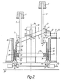
- Each piston 1 is located in a conventional cylinder (not shown) and each piston is mounted on a piston rod 2 which at an intermediate position is provided with a piston control roller 3 (also known as a top control roller, as it determines the top point reached by the piston during its upward travel).
- the piston rod 2 is also provided, near its lower end region, with a weight control roller 4.
- a piston control cam 5 is in two parts, namely a first part 6 and a second part 7.
- the first part 6 of the cam 5 represents a minor arc of a circle and the second part 7 of the cam 5 represents a major arc of the same circle.
- the two end faces of the first part 6 of the cam 5 are planar and parallel, as are also the two end faces of the second part 7 of the cam 5. These planes are vertical.
- a pivotal axis 8 passes through all four end faces of the first and second parts 6, 7 of the cam 5.
- Each end face of the first and second parts 6, 7 of the cam 5, as viewed along the axis 8, has an upper peripheral portion which is circular.
- the whole of the end faces, as viewed along the pivot axis 8, could be circular but this is not of importance.
- the end faces are rectangular apart from an upper, part-circular portion. It is the circularity of the upper portion which is of importance.
- the pivot axis 8 is at a position such that it is at the centre of the circle partly followed by the upper portion of the end faces of the first and second parts 6, 7 of the cam 5.
- the filling head also includes a support 9 on which are provided two blocks 10 provided with two respective horizontal bores 11 in which are located respective rods 12, which are freely movable within the horizontal bores 11.
- a beam 13 mounted on the rods 12 is a beam 13 extending beyond the two rods 12.
- the beam 13 supports the first part 6 of the piston control cam 5.
- the sliding relationship along a horizontal line of action between the rods 12 and the bores 11 permits the beam 13 and hence the first part 6 of the piston control cam 5 to move horizontally in towards, and out from, a vertical line 14 which is the vertical axis of the whole filling head and is the vertical line on which the centre of the piston control cam 5 is to lie.
- the axis 24 rises and falls depending on whether the second part 7 of the cam 5 has been pivoted upwardly or downwardly with respect to the first part 6 of the cam 5.
- the illustrated arrangement ensures that the axis 24 always bisects the vertical line 14.
- a support 25 which cooperates, in sliding relationship, with a guide 28 carried on a block 29.
- the support 25 is provided with a guide 30 which cooperates, in sliding relationship, with a guide 31 carried on a block 32.
- the blocks 29 and 32 are located at diametrically opposed locations on the exterior of a circular weight control cam 33, and the blocks 29 and 32 are provided with internally threaded vertically disposed bores, in which bores the screwthreads engage with external screwthreads on two upright screws 34, 35.
Landscapes
- Engineering & Computer Science (AREA)
- Mechanical Engineering (AREA)
- Basic Packing Technique (AREA)
- Filling Of Jars Or Cans And Processes For Cleaning And Sealing Jars (AREA)
Applications Claiming Priority (2)
| Application Number | Priority Date | Filing Date | Title |
|---|---|---|---|
| GB8814319 | 1988-06-16 | ||
| GB8814319A GB2219835B (en) | 1988-06-16 | 1988-06-16 | Cam system and rotary filling head which includes the system |
Publications (2)
| Publication Number | Publication Date |
|---|---|
| EP0347079A1 true EP0347079A1 (fr) | 1989-12-20 |
| EP0347079B1 EP0347079B1 (fr) | 1992-10-14 |
Family
ID=10638797
Family Applications (1)
| Application Number | Title | Priority Date | Filing Date |
|---|---|---|---|
| EP19890305630 Expired EP0347079B1 (fr) | 1988-06-16 | 1989-06-05 | Système à came et tête de remplissage rotative comprenant le système |
Country Status (3)
| Country | Link |
|---|---|
| EP (1) | EP0347079B1 (fr) |
| DE (1) | DE68903193T2 (fr) |
| GB (1) | GB2219835B (fr) |
Citations (3)
| Publication number | Priority date | Publication date | Assignee | Title |
|---|---|---|---|---|
| US1506851A (en) * | 1921-05-13 | 1924-09-02 | Sprague Canning Machinery Comp | Filling machine |
| US2307214A (en) * | 1940-05-13 | 1943-01-05 | Fmc Corp | Adjustable cam |
| US3400739A (en) * | 1965-03-29 | 1968-09-10 | Remy & Cie E P | Device for metering liquid or semi-fluid products and apparatus incorporating the same |
-
1988
- 1988-06-16 GB GB8814319A patent/GB2219835B/en not_active Expired - Lifetime
-
1989
- 1989-06-05 EP EP19890305630 patent/EP0347079B1/fr not_active Expired
- 1989-06-05 DE DE1989603193 patent/DE68903193T2/de not_active Expired - Fee Related
Patent Citations (3)
| Publication number | Priority date | Publication date | Assignee | Title |
|---|---|---|---|---|
| US1506851A (en) * | 1921-05-13 | 1924-09-02 | Sprague Canning Machinery Comp | Filling machine |
| US2307214A (en) * | 1940-05-13 | 1943-01-05 | Fmc Corp | Adjustable cam |
| US3400739A (en) * | 1965-03-29 | 1968-09-10 | Remy & Cie E P | Device for metering liquid or semi-fluid products and apparatus incorporating the same |
Also Published As
| Publication number | Publication date |
|---|---|
| GB2219835B (en) | 1992-01-02 |
| GB2219835A (en) | 1989-12-20 |
| DE68903193T2 (de) | 1993-02-25 |
| EP0347079B1 (fr) | 1992-10-14 |
| DE68903193D1 (de) | 1992-11-19 |
| GB8814319D0 (en) | 1988-07-20 |
Similar Documents
| Publication | Publication Date | Title |
|---|---|---|
| US4062386A (en) | Method and apparatus for the dosing of dense pasty substances | |
| US4569378A (en) | Filling machine with tandem-operated diaphragm filling units | |
| US3633245A (en) | Apparatus for making and dispensing coherent masses of a bulk material | |
| US5227174A (en) | Apparatus for portioning dough | |
| US4522238A (en) | Valve control mechanism for reciprocating valves of a positive displacement rotary filling machine | |
| US4108221A (en) | Container filling machine | |
| US1073067A (en) | Can-filling machine. | |
| US3587671A (en) | Machine for dispensing predetermined amounts of powdered or granular produce in containers by means of volumetric dispensers | |
| EP0347079B1 (fr) | Système à came et tête de remplissage rotative comprenant le système | |
| AU603905B2 (en) | Adjustable fill motor assembly | |
| US3731715A (en) | Volumetric filling apparatus | |
| US7360483B2 (en) | Device for the guidance of lower rams | |
| US2107274A (en) | Filling machine | |
| JP7449388B2 (ja) | タブレットプレス機械 | |
| US4171933A (en) | Pumping mechanism | |
| US5280815A (en) | Product filling machine | |
| US4473098A (en) | Container transport device for use with filling equipment | |
| US3384035A (en) | Industrial process and apparatus | |
| RU2127523C1 (ru) | Тестоделительная машина | |
| US1506851A (en) | Filling machine | |
| US3046656A (en) | Machine for cutting cheeses of cylindrical shape into sector portions | |
| US2740560A (en) | Measuring and dispensing device | |
| US3980109A (en) | Food dispenser with serving means | |
| US3613747A (en) | Filling head for container filling machine | |
| CA2163184A1 (fr) | Pistons a ressort et barres de degazage pour appareil servant a introduire un materiau de remplissage dans des contenants |
Legal Events
| Date | Code | Title | Description |
|---|---|---|---|
| PUAI | Public reference made under article 153(3) epc to a published international application that has entered the european phase |
Free format text: ORIGINAL CODE: 0009012 |
|
| AK | Designated contracting states |
Kind code of ref document: A1 Designated state(s): CH DE FR IT LI |
|
| 17P | Request for examination filed |
Effective date: 19900516 |
|
| 17Q | First examination report despatched |
Effective date: 19911002 |
|
| GRAA | (expected) grant |
Free format text: ORIGINAL CODE: 0009210 |
|
| AK | Designated contracting states |
Kind code of ref document: B1 Designated state(s): CH DE FR IT LI |
|
| PG25 | Lapsed in a contracting state [announced via postgrant information from national office to epo] |
Ref country code: LI Effective date: 19921014 Ref country code: CH Effective date: 19921014 Ref country code: FR Effective date: 19921014 Ref country code: IT Free format text: LAPSE BECAUSE OF FAILURE TO SUBMIT A TRANSLATION OF THE DESCRIPTION OR TO PAY THE FEE WITHIN THE PRE;WARNING: LAPSES OF ITALIAN PATENTS WITH EFFECTIVE DATE BEFORE 2007 MAY HAVE OCCURRED AT ANY TIME BEFORE 2007. THE CORRECT EFFECTIVE DATE MAY BE DIFFERENT FROM THE ONE RECORDED.SCRIBED TIME-LIMIT Effective date: 19921014 |
|
| REF | Corresponds to: |
Ref document number: 68903193 Country of ref document: DE Date of ref document: 19921119 |
|
| REG | Reference to a national code |
Ref country code: CH Ref legal event code: PL |
|
| EN | Fr: translation not filed | ||
| PLBE | No opposition filed within time limit |
Free format text: ORIGINAL CODE: 0009261 |
|
| STAA | Information on the status of an ep patent application or granted ep patent |
Free format text: STATUS: NO OPPOSITION FILED WITHIN TIME LIMIT |
|
| 26N | No opposition filed | ||
| PGFP | Annual fee paid to national office [announced via postgrant information from national office to epo] |
Ref country code: DE Payment date: 19940525 Year of fee payment: 6 |
|
| PG25 | Lapsed in a contracting state [announced via postgrant information from national office to epo] |
Ref country code: DE Effective date: 19960301 |