EP0346961B1 - Verfahren und Vorrichtung zum Setzen einer Zementauskleidung in einem Bohrloch - Google Patents
Verfahren und Vorrichtung zum Setzen einer Zementauskleidung in einem Bohrloch Download PDFInfo
- Publication number
- EP0346961B1 EP0346961B1 EP89201346A EP89201346A EP0346961B1 EP 0346961 B1 EP0346961 B1 EP 0346961B1 EP 89201346 A EP89201346 A EP 89201346A EP 89201346 A EP89201346 A EP 89201346A EP 0346961 B1 EP0346961 B1 EP 0346961B1
- Authority
- EP
- European Patent Office
- Prior art keywords
- stinger
- borehole
- cement
- tubing
- mud
- Prior art date
- Legal status (The legal status is an assumption and is not a legal conclusion. Google has not performed a legal analysis and makes no representation as to the accuracy of the status listed.)
- Expired - Lifetime
Links
- 239000004568 cement Substances 0.000 title claims description 102
- 238000000034 method Methods 0.000 title claims description 23
- 239000002002 slurry Substances 0.000 claims description 35
- 238000002156 mixing Methods 0.000 claims description 17
- 238000005553 drilling Methods 0.000 claims description 10
- 238000005086 pumping Methods 0.000 claims description 3
- 239000003381 stabilizer Substances 0.000 description 5
- 239000000203 mixture Substances 0.000 description 4
- 229910000831 Steel Inorganic materials 0.000 description 3
- 239000012530 fluid Substances 0.000 description 3
- 239000010959 steel Substances 0.000 description 3
- 239000004593 Epoxy Substances 0.000 description 2
- 239000000654 additive Substances 0.000 description 2
- 239000000440 bentonite Substances 0.000 description 2
- 229910000278 bentonite Inorganic materials 0.000 description 2
- SVPXDRXYRYOSEX-UHFFFAOYSA-N bentoquatam Chemical compound O.O=[Si]=O.O=[Al]O[Al]=O SVPXDRXYRYOSEX-UHFFFAOYSA-N 0.000 description 2
- 229920001971 elastomer Polymers 0.000 description 2
- 239000011396 hydraulic cement Substances 0.000 description 2
- 238000002347 injection Methods 0.000 description 2
- 239000007924 injection Substances 0.000 description 2
- 239000002516 radical scavenger Substances 0.000 description 2
- 238000009416 shuttering Methods 0.000 description 2
- OKTJSMMVPCPJKN-UHFFFAOYSA-N Carbon Chemical compound [C] OKTJSMMVPCPJKN-UHFFFAOYSA-N 0.000 description 1
- JZUFKLXOESDKRF-UHFFFAOYSA-N Chlorothiazide Chemical compound C1=C(Cl)C(S(=O)(=O)N)=CC2=C1NCNS2(=O)=O JZUFKLXOESDKRF-UHFFFAOYSA-N 0.000 description 1
- 239000004743 Polypropylene Substances 0.000 description 1
- 239000011398 Portland cement Substances 0.000 description 1
- 238000010420 art technique Methods 0.000 description 1
- 238000000429 assembly Methods 0.000 description 1
- 230000000712 assembly Effects 0.000 description 1
- 230000015572 biosynthetic process Effects 0.000 description 1
- 239000011248 coating agent Substances 0.000 description 1
- 238000000576 coating method Methods 0.000 description 1
- 230000003247 decreasing effect Effects 0.000 description 1
- 125000003700 epoxy group Chemical group 0.000 description 1
- 238000002474 experimental method Methods 0.000 description 1
- 239000012065 filter cake Substances 0.000 description 1
- 238000005755 formation reaction Methods 0.000 description 1
- 239000008187 granular material Substances 0.000 description 1
- 239000010439 graphite Substances 0.000 description 1
- 229910002804 graphite Inorganic materials 0.000 description 1
- 230000005484 gravity Effects 0.000 description 1
- 238000011065 in-situ storage Methods 0.000 description 1
- 230000001788 irregular Effects 0.000 description 1
- 229920000126 latex Polymers 0.000 description 1
- 239000004816 latex Substances 0.000 description 1
- 230000000704 physical effect Effects 0.000 description 1
- 229920000647 polyepoxide Polymers 0.000 description 1
- 229920000642 polymer Polymers 0.000 description 1
- -1 polypropylene Polymers 0.000 description 1
- 229920001155 polypropylene Polymers 0.000 description 1
- 239000011347 resin Substances 0.000 description 1
- 229920005989 resin Polymers 0.000 description 1
- 238000004513 sizing Methods 0.000 description 1
- 239000007787 solid Substances 0.000 description 1
- 230000006641 stabilisation Effects 0.000 description 1
- 238000011105 stabilization Methods 0.000 description 1
Images


Classifications
-
- E—FIXED CONSTRUCTIONS
- E21—EARTH OR ROCK DRILLING; MINING
- E21B—EARTH OR ROCK DRILLING; OBTAINING OIL, GAS, WATER, SOLUBLE OR MELTABLE MATERIALS OR A SLURRY OF MINERALS FROM WELLS
- E21B17/00—Drilling rods or pipes; Flexible drill strings; Kellies; Drill collars; Sucker rods; Cables; Casings; Tubings
- E21B17/10—Wear protectors; Centralising devices, e.g. stabilisers
- E21B17/1078—Stabilisers or centralisers for casing, tubing or drill pipes
-
- E—FIXED CONSTRUCTIONS
- E21—EARTH OR ROCK DRILLING; MINING
- E21B—EARTH OR ROCK DRILLING; OBTAINING OIL, GAS, WATER, SOLUBLE OR MELTABLE MATERIALS OR A SLURRY OF MINERALS FROM WELLS
- E21B33/00—Sealing or packing boreholes or wells
- E21B33/10—Sealing or packing boreholes or wells in the borehole
- E21B33/13—Methods or devices for cementing, for plugging holes, crevices or the like
- E21B33/138—Plastering the borehole wall; Injecting into the formation
Definitions
- the invention relates to a method and apparatus for placing a cement lining alongside the wall of a borehole.
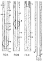
- the stinger spots a mud channel 15 in the plug of cement slurry 3.
- the diameter of the mud channel does not depend on the diameter of the outlet 9 of the stinger 6 but on the outer diameter of the tubing 5 which is pulled through the collar.
- the same bit 17 may be used to drill a next section of the borehole after the hole bottom 10 has been reached.
- Said next section may have a smaller diameter than the previously treated sections and may be provided with a cement lining which is placed using the same procedure as described above.
Landscapes
- Engineering & Computer Science (AREA)
- Life Sciences & Earth Sciences (AREA)
- Geology (AREA)
- Mining & Mineral Resources (AREA)
- Physics & Mathematics (AREA)
- Environmental & Geological Engineering (AREA)
- Fluid Mechanics (AREA)
- General Life Sciences & Earth Sciences (AREA)
- Geochemistry & Mineralogy (AREA)
- Mechanical Engineering (AREA)
- Consolidation Of Soil By Introduction Of Solidifying Substances Into Soil (AREA)
- Underground Or Underwater Handling Of Building Materials (AREA)
Claims (8)
- Verfahren zum Setzen einer Zementauskleidung (2) entlang der Wand eines Bohrlochs (1), bei dem man:- ein Rohrgestänge (5 und 6) in das Bohrloch (1) herabläßt, bis das untere Ende des Rohrgestänges (5 und 6) die Sohle eines Abschnitts des auszukleidenden Bohrlochs (1) erreicht hat,- einen Zementschlamm (3) in einen Ringraum (7) um das Rohrgestänge (5 und 6) herum einbringt und einen Stoß Bohrschlamm (13) in das Rohrgestänge (5 und 6) einpumpt, bis der Schlamm (13) im wesentlichen das untere Ende des Rohrgestänges (5 und 6) erreicht hat und der Zementschlamm (3) im wesentlichen den Ringraum (7) über die Lange des auszukleidenden Bohrlochabschnitts ausfüllt,- das Rohrgestänge (5 und 6) durch das Bohrloch (1) heraufzieht und- den Zement abbinden läßt,dadurch gekennzeichnet, daß das Rohrgestänge (5 und 6) eine mit dem unteren Ende eines Rohrs (5) verbundene Vorschubstange (6) umfaßt, daß die Vorschubstange (6) mit einem Mischübergangsstück (22) versehen ist, das aus einem rohrförmigen Element mit einem Innendurchmesser besteht, der größer ist als der Außendurchmesser des Rohrs (5), wobei innerhalb des Übergangsstücks (22) eine Mischvorrichtung (24) angeordnet ist und wobei innerhalb des Übergangsstücks (22) Zement und Schlamm unter der Einwirkung des Heraufziehens des Rohrs (5) und der Vorschubstange (6) durch das Bohrloch (1) zu einem weichen Zementkern vermischt werden, und daß während des Heraufziehens des Rohrs (5) und der Vorschubstange (6) durch das Bohrloch (1) die Vorschubstange (6) im Bohrloch (1) unter Anwendung von Zentriermitteln (8) zentriert wird, die mit der Bohrlochwand in Berührung gehalten werden und den Zementschlamm (3) entlang der Bohrlochwand durchschleppen.
- Verfahren nach Anspruch 1, wobei die Vorschubstange (6) im Bohrloch (1) durch Zentriermittel (8) zentriert wird, die aus einer Reihe in der Nähe des unteren Endes der Vorschubstange (6) angebrachter Zentrierbogenfederblätter (30) bestehen.
- Verfahren nach Anspruch 2, wobei die Zentriermittel (8) ferner mit starren Rippen (29) versehen sind, die in gleichen Winkelabständen verteilt um die Vorschubstange (6) herum angebracht sind.
- Verfahren nach Anspruch 1, wobei hinter dem Zementschlamm (3) ein Stoß Bentonitschlamm (13) in das Rohr (5) und die Vorschubstange (6) gepumpt wird, wobei der Schlamm (13) eine Dichte besitzt, die weitgehend gleich derjenigen des Zementschlamms (3) ist.
- Verfahren nach Anspruch 1, wobei nach dem Schritt des Pumpens des Schlamms (13) in das Rohr (5) und die Vorschubstange (6) der Ringraum (7) entweder am Bohrlochkopf oder an der Krone des auszukleidenden Bohrlochabschnitts geschlossen wird.
- Verfahren nach Anspruch 1, wobei vor dem Herablassen des Rohrs (5) und der Vorschubstange (6) in das Bohrloch (1) ein Zementschlamm (3) so in das Bohrloch (1) eingeführt wird, daß der Zementschlamm (3) einen unteren Abschnitt des Bohrlochs (1) völlig ausfüllt, woraufhin nach dem Herablassen des Rohrs (5) und der Vorschubstange (6) auf die Sohle des Bohrlochs Bohrschlamm in das Innere des Rohrs (5) und der Vorschubstange (6) eingepreßt wird, bis der Schlamm das untere Ende der Vorschubstange (6) erreicht hat.
- Verfahren nach einem der Ansprüche 1 bis 6, wobei man nach dem Erhärten des Zements eine Bohrvorrichtung (17) in das Bohrloch (1) herabläßt und zum Bohren eines offenen Raums gewünschter Breite im Zentrum des Zementpfropfens in Gang setzt.
- Vorrichtung zum Setzen einer Zementauskleidung entlang der Wand eines Bohrlochs (1), wobei die Vorrichtung aus einer mit einem Ende eines Rohrs (5) verbundenen Vorschubstange (6) und Mitteln zum Zentrieren der Vorschubstange (6) im Bohrloch (1) besteht und wobei die Zentriermittel (8) aus einer Reihe von Zentrierelementen bestehen, die seitlich von der Vorschubstange (6) so abstehen, daß die Elemente im Gebrauch in Berührung mit der Bohrlochwand gehalten werden, dadurch gekennzeichnet, daß die Vorschubstange (6) mit einem Mischübergangsstück (22) versehen ist, wobei das Übergangsstück (22) aus einem rohrförmigen, koaxial um das untere Ende der Vorschubstange (6) herum angeordneten Element und einer innerhalb des Übergangsstücks (22) unter dem unteren Ende der Vorschubstange (6) und auf dieses weisend angeordneten konischen Mischvorrichtung (24) besteht, um Zement und Schlamm während des Heraufziehens des Rohrs (5) und der Vorschubstange (6) durch das Bohrloch (1) zu einem weichen Zementkern zu vermischen.
Applications Claiming Priority (2)
| Application Number | Priority Date | Filing Date | Title |
|---|---|---|---|
| GB8814004 | 1988-06-14 | ||
| GB888814004A GB8814004D0 (en) | 1988-06-14 | 1988-06-14 | Method & apparatus for placing cement lining in borehole |
Publications (3)
| Publication Number | Publication Date |
|---|---|
| EP0346961A2 EP0346961A2 (de) | 1989-12-20 |
| EP0346961A3 EP0346961A3 (de) | 1991-05-15 |
| EP0346961B1 true EP0346961B1 (de) | 1995-07-26 |
Family
ID=10638584
Family Applications (1)
| Application Number | Title | Priority Date | Filing Date |
|---|---|---|---|
| EP89201346A Expired - Lifetime EP0346961B1 (de) | 1988-06-14 | 1989-05-25 | Verfahren und Vorrichtung zum Setzen einer Zementauskleidung in einem Bohrloch |
Country Status (5)
| Country | Link |
|---|---|
| EP (1) | EP0346961B1 (de) |
| CA (1) | CA1324573C (de) |
| DE (1) | DE68923585T2 (de) |
| GB (1) | GB8814004D0 (de) |
| NO (1) | NO302136B1 (de) |
Families Citing this family (7)
| Publication number | Priority date | Publication date | Assignee | Title |
|---|---|---|---|---|
| GB8913647D0 (en) * | 1989-06-14 | 1989-08-02 | Shell Int Research | Method of drilling and lining a borehole |
| AU2004265583B2 (en) | 2003-07-25 | 2009-06-04 | Exxonmobil Upstream Research Company | Continuous monobore liquid lining system |
| CN103452525B (zh) * | 2013-09-06 | 2016-08-10 | 河南理工大学 | 瓦斯抽釆固定式封堵器及其使用方法 |
| GB2518612B (en) | 2013-09-25 | 2020-07-15 | Equinor Energy As | Method of sealing a well |
| WO2017108820A1 (en) * | 2015-12-23 | 2017-06-29 | Shell Internationale Research Maatschappij B.V. | Configuring a velocity string in a production tubing of a wet gas production well |
| CN110863794B (zh) * | 2019-12-23 | 2024-12-03 | 天地科技股份有限公司 | 钻孔固管装置 |
| AU2021277744A1 (en) * | 2021-12-03 | 2023-06-22 | Manja, Feras MR | Implementation of soiled consolidation treatment / fluids in newly drilled CSG / CBM wells. |
Family Cites Families (6)
| Publication number | Priority date | Publication date | Assignee | Title |
|---|---|---|---|---|
| US2387002A (en) * | 1942-06-24 | 1945-10-16 | Clyde E Bannister | Apparatus for cementing the wall of an earth boring |
| US3526280A (en) * | 1967-10-17 | 1970-09-01 | Halliburton Co | Method for flotation completion for highly deviated wells |
| US3774683A (en) * | 1972-05-23 | 1973-11-27 | Halliburton Co | Method for stabilizing bore holes |
| US3976139A (en) * | 1974-12-30 | 1976-08-24 | Standard Oil Company (Indiana) | Anchoring for tensioning casing in thermal wells |
| GB2134947A (en) * | 1983-02-14 | 1984-08-22 | Texas Iron Works | Cementing casings and liners in wellbores |
| US4519452A (en) * | 1984-05-31 | 1985-05-28 | Exxon Production Research Co. | Method of drilling and cementing a well using a drilling fluid convertible in place into a settable cement slurry |
-
1988
- 1988-06-14 GB GB888814004A patent/GB8814004D0/en active Pending
-
1989
- 1989-05-25 DE DE68923585T patent/DE68923585T2/de not_active Expired - Fee Related
- 1989-05-25 EP EP89201346A patent/EP0346961B1/de not_active Expired - Lifetime
- 1989-05-30 CA CA000601120A patent/CA1324573C/en not_active Expired - Fee Related
- 1989-06-12 NO NO892412A patent/NO302136B1/no unknown
Also Published As
| Publication number | Publication date |
|---|---|
| DE68923585T2 (de) | 1996-02-29 |
| DE68923585D1 (de) | 1995-08-31 |
| EP0346961A3 (de) | 1991-05-15 |
| GB8814004D0 (en) | 1988-07-20 |
| NO302136B1 (no) | 1998-01-26 |
| CA1324573C (en) | 1993-11-23 |
| EP0346961A2 (de) | 1989-12-20 |
| NO892412L (no) | 1989-12-15 |
| NO892412D0 (no) | 1989-06-12 |
Similar Documents
| Publication | Publication Date | Title |
|---|---|---|
| US5842518A (en) | Method for drilling a well in unconsolidated and/or abnormally pressured formations | |
| EP0229425B1 (de) | Verfahren und Vorrichtung zum Auskleiden einer Bohrlochswand | |
| US4595058A (en) | Turbulence cementing sub | |
| US20020023754A1 (en) | Method for drilling multilateral wells and related device | |
| US3572432A (en) | Apparatus for flotation completion for highly deviated wells | |
| US4436165A (en) | Drain hole drilling | |
| CA1167832A (en) | Reduction of the frictional coefficient in a borehole by the use of vibration | |
| EP1701000B1 (de) | Verfahren und Vorrichtung für die Konsolidierung eines Bohrlochs | |
| US5289876A (en) | Completing wells in incompetent formations | |
| US3526280A (en) | Method for flotation completion for highly deviated wells | |
| US4869323A (en) | Cementing and rotating an upper well casing attached by swivel to a lower casing | |
| EP0287735A2 (de) | Verfahren zur Ausrüstung eines Dränbohrloches | |
| US4616719A (en) | Casing lateral wells | |
| ITMI952418A1 (it) | Metodo per l'esclusione sotterranea di fluidi | |
| US7475726B2 (en) | Continuous monobore liquid lining system | |
| US6712144B2 (en) | Method for drilling multilateral wells with reduced under-reaming and related device | |
| EP0346961A2 (de) | Verfahren und Vorrichtung zum Setzen einer Zementauskleidung in einem Bohrloch | |
| EP0186317A1 (de) | Verfahren und Vorrichtung zur Verrohrung stark abgelenkter Bohrlöcher | |
| EP1043477B1 (de) | Verfahren und Vorrichtung zum Ausrüsten eines Bohrloches zur Gewinnung von Kohlenwasserstoffen oder dergleichen | |
| EP0403025B1 (de) | Verfahren zum Bohren und Auskleiden eines Bohrlochs | |
| US4759408A (en) | Method of shutting off a portion of a producing zone in a hydrocarbon producing well | |
| CA2212198C (en) | Well stabilization tools and methods | |
| RU2769020C1 (ru) | Способ цементирования хвостовика с вращением | |
| RU2723814C2 (ru) | Способ строительства скважины | |
| WO1987002409A1 (en) | Turbulence cementing sub |
Legal Events
| Date | Code | Title | Description |
|---|---|---|---|
| PUAI | Public reference made under article 153(3) epc to a published international application that has entered the european phase |
Free format text: ORIGINAL CODE: 0009012 |
|
| AK | Designated contracting states |
Kind code of ref document: A2 Designated state(s): DE FR GB IT NL |
|
| PUAL | Search report despatched |
Free format text: ORIGINAL CODE: 0009013 |
|
| AK | Designated contracting states |
Kind code of ref document: A3 Designated state(s): DE FR GB IT NL |
|
| 17P | Request for examination filed |
Effective date: 19910925 |
|
| 17Q | First examination report despatched |
Effective date: 19930730 |
|
| GRAA | (expected) grant |
Free format text: ORIGINAL CODE: 0009210 |
|
| AK | Designated contracting states |
Kind code of ref document: B1 Designated state(s): DE FR GB IT NL |
|
| ITF | It: translation for a ep patent filed | ||
| REF | Corresponds to: |
Ref document number: 68923585 Country of ref document: DE Date of ref document: 19950831 |
|
| ET | Fr: translation filed | ||
| PLBE | No opposition filed within time limit |
Free format text: ORIGINAL CODE: 0009261 |
|
| STAA | Information on the status of an ep patent application or granted ep patent |
Free format text: STATUS: NO OPPOSITION FILED WITHIN TIME LIMIT |
|
| 26N | No opposition filed | ||
| PGFP | Annual fee paid to national office [announced via postgrant information from national office to epo] |
Ref country code: FR Payment date: 19970324 Year of fee payment: 9 |
|
| PGFP | Annual fee paid to national office [announced via postgrant information from national office to epo] |
Ref country code: GB Payment date: 19970424 Year of fee payment: 9 |
|
| PGFP | Annual fee paid to national office [announced via postgrant information from national office to epo] |
Ref country code: NL Payment date: 19970527 Year of fee payment: 9 |
|
| PGFP | Annual fee paid to national office [announced via postgrant information from national office to epo] |
Ref country code: DE Payment date: 19970609 Year of fee payment: 9 |
|
| PG25 | Lapsed in a contracting state [announced via postgrant information from national office to epo] |
Ref country code: GB Free format text: LAPSE BECAUSE OF NON-PAYMENT OF DUE FEES Effective date: 19980525 |
|
| PG25 | Lapsed in a contracting state [announced via postgrant information from national office to epo] |
Ref country code: FR Free format text: LAPSE BECAUSE OF NON-PAYMENT OF DUE FEES Effective date: 19980531 |
|
| PG25 | Lapsed in a contracting state [announced via postgrant information from national office to epo] |
Ref country code: NL Free format text: LAPSE BECAUSE OF NON-PAYMENT OF DUE FEES Effective date: 19981201 |
|
| GBPC | Gb: european patent ceased through non-payment of renewal fee |
Effective date: 19980525 |
|
| NLV4 | Nl: lapsed or anulled due to non-payment of the annual fee |
Effective date: 19981201 |
|
| PG25 | Lapsed in a contracting state [announced via postgrant information from national office to epo] |
Ref country code: DE Free format text: LAPSE BECAUSE OF NON-PAYMENT OF DUE FEES Effective date: 19990302 |
|
| REG | Reference to a national code |
Ref country code: FR Ref legal event code: ST |
|
| PG25 | Lapsed in a contracting state [announced via postgrant information from national office to epo] |
Ref country code: IT Free format text: LAPSE BECAUSE OF NON-PAYMENT OF DUE FEES;WARNING: LAPSES OF ITALIAN PATENTS WITH EFFECTIVE DATE BEFORE 2007 MAY HAVE OCCURRED AT ANY TIME BEFORE 2007. THE CORRECT EFFECTIVE DATE MAY BE DIFFERENT FROM THE ONE RECORDED. Effective date: 20050525 |