EP0346948A2 - Framework consisting of bar-shaped elements - Google Patents
Framework consisting of bar-shaped elements Download PDFInfo
- Publication number
- EP0346948A2 EP0346948A2 EP19890115135 EP89115135A EP0346948A2 EP 0346948 A2 EP0346948 A2 EP 0346948A2 EP 19890115135 EP19890115135 EP 19890115135 EP 89115135 A EP89115135 A EP 89115135A EP 0346948 A2 EP0346948 A2 EP 0346948A2
- Authority
- EP
- European Patent Office
- Prior art keywords
- core part
- framework according
- axes
- polygonal
- shaped elements
- Prior art date
- Legal status (The legal status is an assumption and is not a legal conclusion. Google has not performed a legal analysis and makes no representation as to the accuracy of the status listed.)
- Granted
Links
Images


Classifications
-
- F—MECHANICAL ENGINEERING; LIGHTING; HEATING; WEAPONS; BLASTING
- F16—ENGINEERING ELEMENTS AND UNITS; GENERAL MEASURES FOR PRODUCING AND MAINTAINING EFFECTIVE FUNCTIONING OF MACHINES OR INSTALLATIONS; THERMAL INSULATION IN GENERAL
- F16B—DEVICES FOR FASTENING OR SECURING CONSTRUCTIONAL ELEMENTS OR MACHINE PARTS TOGETHER, e.g. NAILS, BOLTS, CIRCLIPS, CLAMPS, CLIPS OR WEDGES; JOINTS OR JOINTING
- F16B7/00—Connections of rods or tubes, e.g. of non-circular section, mutually, including resilient connections
- F16B7/04—Clamping or clipping connections
- F16B7/044—Clamping or clipping connections for rods or tubes being in angled relationship
- F16B7/0446—Clamping or clipping connections for rods or tubes being in angled relationship for tubes using the innerside thereof
-
- E—FIXED CONSTRUCTIONS
- E04—BUILDING
- E04B—GENERAL BUILDING CONSTRUCTIONS; WALLS, e.g. PARTITIONS; ROOFS; FLOORS; CEILINGS; INSULATION OR OTHER PROTECTION OF BUILDINGS
- E04B1/00—Constructions in general; Structures which are not restricted either to walls, e.g. partitions, or floors or ceilings or roofs
- E04B1/343—Structures characterised by movable, separable, or collapsible parts, e.g. for transport
- E04B1/344—Structures characterised by movable, separable, or collapsible parts, e.g. for transport with hinged parts
- E04B1/3441—Structures characterised by movable, separable, or collapsible parts, e.g. for transport with hinged parts with articulated bar-shaped elements
-
- F—MECHANICAL ENGINEERING; LIGHTING; HEATING; WEAPONS; BLASTING
- F16—ENGINEERING ELEMENTS AND UNITS; GENERAL MEASURES FOR PRODUCING AND MAINTAINING EFFECTIVE FUNCTIONING OF MACHINES OR INSTALLATIONS; THERMAL INSULATION IN GENERAL
- F16B—DEVICES FOR FASTENING OR SECURING CONSTRUCTIONAL ELEMENTS OR MACHINE PARTS TOGETHER, e.g. NAILS, BOLTS, CIRCLIPS, CLAMPS, CLIPS OR WEDGES; JOINTS OR JOINTING
- F16B5/00—Joining sheets or plates, e.g. panels, to one another or to strips or bars parallel to them
- F16B5/06—Joining sheets or plates, e.g. panels, to one another or to strips or bars parallel to them by means of clamps or clips
- F16B5/0685—Joining sheets or plates to strips or bars
-
- Y—GENERAL TAGGING OF NEW TECHNOLOGICAL DEVELOPMENTS; GENERAL TAGGING OF CROSS-SECTIONAL TECHNOLOGIES SPANNING OVER SEVERAL SECTIONS OF THE IPC; TECHNICAL SUBJECTS COVERED BY FORMER USPC CROSS-REFERENCE ART COLLECTIONS [XRACs] AND DIGESTS
- Y10—TECHNICAL SUBJECTS COVERED BY FORMER USPC
- Y10T—TECHNICAL SUBJECTS COVERED BY FORMER US CLASSIFICATION
- Y10T403/00—Joints and connections
- Y10T403/55—Member ends joined by inserted section
- Y10T403/557—Expansible section
Definitions
- the invention relates to a skeleton consisting of rod-shaped elements according to the preamble of claim 1.
- Such skeletons enable the rapid construction of a spatial structure for a wide variety of purposes.
- Generically comparable skeletons have become known, for example, from US-A-4,290,244 or WO-A-84/01094.
- the connecting elements are firmly bumped into the ends of the rod-shaped elements, a plurality of connecting elements in each case being articulated at a node.
- the connecting elements have no actual gripping devices, but are provided with transverse pins which are enclosed in the two-part core parts.
- a disadvantage of these constructions is in particular that only a very specific structure can be built at a time. Modifications or the attachment or omission of individual elements are not possible for the user, since the individual components of the framework are firmly connected to one another. Removing a single part of the forest would also make the entire structure unstable.
- Connecting elements with gripping devices are known from DE-A-20 24 508 or from DE-A-22 51 228 the. In both cases, however, no core parts are provided for the formation of a knot.
- the skeleton should also allow modifications to existing structures, so that the user is not dependent on specialists if he wants to make structural changes on site at short notice.
- the axes are preferably round or polygonal in cross-section, the gripping devices gripping the axes in a form-fitting manner.
- the gripping devices gripping the axes in a form-fitting manner.
- the core part can be designed as a polyhedron or as a flat body, the axes of which lie in one plane.
- the function of the gripping device is particularly efficient if the connecting elements are designed to be divided in the plane of the tube axis and if the gripping device consists of two half-shells.
- the half-shells can be hollow-cylindrical or with a polygonal cross-section for gripping an axis.
- the two half-shells can be closed about an axis of the core part, so that an articulated or non-rotatable connection is created, which can however be released at any time.
- the core part is approximately square and has two axial sections on each side, each of which can accommodate a gripping device, two rods can be connected on one side. This facilitates the construction of three-dimensional structures and the construction of foldable structures with crossing bars.
- the width of the axle sections on the sides of the core part corresponds to the width of a gripping device, a stable connection is ensured.
- the core part is divided into two halves that can be joined or plugged together and have identical shapes, which are provided on the inside with diametrically opposed pins and bores.
- the core parts can also have holes in the center and / or at the corners for connecting elements, such as screws, push buttons or other axis elements.
- Two connecting elements can be joined together in a rotationally fixed manner if one has a polygonal depression and the other has a polygonal flange which fits into the depression in a form-fitting manner.
- Two core parts can also be connected at a distance from one another with a spacer tube.
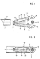
- a typical connecting element 4 consists of the two halves 6 and 6 ', which are preferably absolutely identical.
- the connecting elements are preferably made of plastic material by injection molding.
- the two halves 6 and 6 ' are put together on a locking device 7 so that they can be opened and closed like a hinge.
- a recess 10 is provided in the shaft 3 of the connecting element, which merges into an opening 21 at one point.
- the recess 10 serves to receive the spring element 11, which in the present exemplary embodiment is designed as a U-shaped bracket.
- Each spring element carries a cam 13 which projects from the opening 21 in the closed state.
- a positioning cam 22 is arranged on the lower leg of the U-shaped bracket, but only partially penetrates the opening 21 and is used only for positioning the spring element 11.
- Each connecting element is provided with a gripping device 14, which in the present case consists of the two half-shells 5 and 5 '. These two half-shells are designed so that they can grip an axis 12 in a form-fitting manner.
- a circumferential shoulder 37 delimits the shaft 3, the shoulder preferably having a height which corresponds approximately to the wall thickness of the tubes.
- the rod-shaped element 2 is to be connected with its tubular end to the axis 12.
- the tubular element 2 is provided with an opening 8, the diameter of which is somewhat larger than the diameter of the Nockens 13.
- the connecting element is now opened so far that the two half-shells 5 and 5 'can take the axis 12.
- the connecting element is then closed, the cam 13 protruding from the opening 21.
- the shaft 3 of the closed connecting element is then pushed into the element 2.
- the cam 13 is pressed inwards until it reaches the opening 8, where it engages due to the spring action, as shown in FIG. 2.
- the cam 13 To remove the connecting element from the element 2, the cam 13 must be pressed inward again so that the lock is released. This can be done in the simplest way by hand or with the aid of a screwdriver or the like.
- the axis 12 or the half-shells 5 could also e.g. have a hexagonal or quadrangular cross section, so that it would not be possible to rotate the axis when the connecting element is closed.
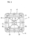
- Figures 3 to 5 show a core part 9 in the form of a square, flat body, to which several rod-shaped elements can be connected.
- this part is also divided into two halves, which are of identical shape and can be inserted into one another, as shown in particular in FIG. 5.
- diametrically opposite pins 28 and bores 29 are provided on the inside.
- a depression 30 is provided in the center, which, for example, can accommodate a hexagonal body in a rotationally fixed manner.
- the through hole 31 and the holes 66 are used for took a screw to connect the core part with other components.
- a push button 67 could also be used, the two resilient lugs 68 of which can be pressed together.
- the same push button could also be inserted through the closed half-shells of a connecting element.
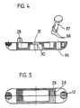
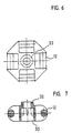
- FIGS. 6 and 7 Another type of core part is shown in FIGS. 6 and 7, which is somewhat smaller and has only a single axle section 12 on each side.
- a hexagon flange 32 is arranged on one side, which fits positively into the recess 30 of the core part according to FIG. 3.
- the recess 33 serves to receive a screw head or the flange of an adjacent core part.
- FIG. 8 shows the combination of two core parts according to FIGS. 3 and 6.
- the small core part 63 is inserted into the large core part 64, the hexagonal flange 32 penetrating into the depression 30.
- the two parts 63 and 64 are non-positively connected to one another with a fastening screw, not shown.
- the core parts can also have other configurations and can, for example, be hexagonal, triangular or also formed as a polyhedron.
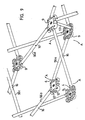
- FIGS. 9 and 10 framework structures 1 are described, which represent a flat spatial structure.
- Individual pairs of rods or scissors 56 are connected to one another to form closed units with a polygonal grid.
- Such a closed unit consisting of the four scissors 56a, 56b, 56c and 56d, is shown in FIG.
- the ends of the scissors 56 are articulated to one another by means of the large core parts 9.
- the individual tubes of the scissors 56 are offset from one another by a tube thickness, a connection to an axle section 12 or 12 'is alternately required.
- Each closed unit can be folded into a structure in which all the rods of the individual scissors 56 run almost parallel to one another and are close to one another.
- Each individual pair of scissors performs a pivoting movement around the intersection 16, as indicated by the direction of arrow A.
- the rod-shaped elements 2 are connected to one another in an articulated manner by means of screws or the like.
- two core parts 9 are connected to a spacer tube 57.
- This can, as in FIG. 9, be connected to the axes 12 or, as shown in FIG. 10, in the center of the core parts 9.
- the spacer tube can be provided on both sides with the push button already mentioned.
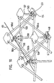
- FIG. 10 again shows a closed unit consisting of four scissors 56a, 56b, 56c and 56d connected to one another, as has already been shown in FIG.
- the closed unit is reinforced with a pyramid-like rod structure, each rod 58 of this rod structure being connected to a connection point between two scissors.
- the connection point is constructed approximately according to FIG. 8 and consists of a small core part 63 which is fastened on a large core part 64.
- the pyramid rods 58 meet at the pyramid tip 59 and are connected there to form a node, as is shown, for example, in FIG. 11.
- another closed unit with a pyramid tip 59 ' is partially shown on the left side.
- the pyramid-like rod structures serve to reinforce the closed units in the horizontal plane, so that for example, ceiling structures can be built.
- the adjacent pyramid tips 59, 59 ', etc. are preferably connected to one another via a cable 61. Instead of the cable, another rod or surface can of course be used.
- the cable pull has the advantage that the entire frame can be folded up, the cable pull hanging loosely in the folded-up state.
- the length of the pyramid rods 58 must be selected such that they do not hinder the folding of the scissors 56.
- the pyramid tips on a ceiling construction can be directed either upwards or downwards or in both directions. The sag of a ceiling construction can be corrected with the cable 61.
- the pyramid tips also create a further connection level, on which additional structures can be built using core parts.
- FIG. 11 shows a pyramid tip, the small core part 63 being provided with a cable pull holder 62. A cable can be pulled into this and clamped with a locking screw 60.
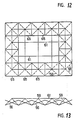
- FIGS. 12 and 13 show a construction with a horizontal extension consisting of a plurality of closed units 65 arranged in a row.
- the pyramid rods 58 are shown as broken lines.
- the cables 61 connect the neighboring pyramid tips in a straight line.
- dome-like structures can also be erected, e.g. can be used as emergency accommodation with suitable covering.
Landscapes
- Engineering & Computer Science (AREA)
- General Engineering & Computer Science (AREA)
- Architecture (AREA)
- Mechanical Engineering (AREA)
- Electromagnetism (AREA)
- Civil Engineering (AREA)
- Structural Engineering (AREA)
- Physics & Mathematics (AREA)
- Mutual Connection Of Rods And Tubes (AREA)
- Joining Of Building Structures In Genera (AREA)
- Superconductors And Manufacturing Methods Therefor (AREA)
- Prostheses (AREA)
- Assembled Shelves (AREA)
- Variable-Direction Aerials And Aerial Arrays (AREA)
- Pit Excavations, Shoring, Fill Or Stabilisation Of Slopes (AREA)
- Rod-Shaped Construction Members (AREA)
- Grates (AREA)
- Manufacturing Of Tubular Articles Or Embedded Moulded Articles (AREA)
Abstract
Für den Aufbau eines Gerippes können mehrere stabförmige Elemente (2) an ein Kernelement (63, 64) angeschlossen werden, das als mehreckiger Körper ausgebildet ist und das an den Seitenkanten Kupplungsmittel in der Form von Achsen (12) aufweist. 
Description
Die Erfindung bezieht sich auf ein Gerippe bestehend aus stabförmigen Elementen gemäss dem Oberbegriff von Anspruch 1. Derartige Gerippe ermöglichen den raschen Aufbau einer Raumstruktur für die verschiedensten Zwecke. Sie werden heute beispielsweise in zunehmendem Masse im Ausstellungsbau für den Aufbau von Schauwänden oder für die Konstruktion ganzer Standaufbauten eingesetzt. Denkbar ist aber auch die Konstruktion von Möbeln oder von behelfsmässigen Notunterkünften sowie von Kuppeln und dergleichen mehr.The invention relates to a skeleton consisting of rod-shaped elements according to the preamble of claim 1. Such skeletons enable the rapid construction of a spatial structure for a wide variety of purposes. Today, for example, they are increasingly used in exhibition construction for the construction of display walls or for the construction of entire stand structures. But it is also conceivable to construct furniture or makeshift emergency shelters as well as domes and the like.
Gattunsmässig vergleichbare Gerippe sind beispielsweise durch die US-A-4,290,244 oder die WO-A-84/01094 bekannt geworden. Bei den dort dargestellten und beschriebenen Konstruktionen sind die Verbindungselemente fest in die Enden der stabförmigen Elemente eingeprellt, wobei jeweils mehrere Verbindungselemente fest an einem Knotenpunkt angelenkt sind. Die Verbindungselemente haben keine eigentlichen Greifvorrichtungen, sondern sind mit querstehenden Zapfen versehen, welche in die zweiteiligen Kernteile eingeschlossen werden. Ein Nachteil dieser Konstruktionen besteht insbesondere darin, dass jeweils nur eine ganz bestimmte Struktur aufgebaut werden kann. Modifikationen oder das Anbauen oder Weglassen einzelner Elemente sind für den Anwender nicht möglich, da die einzelnen Bauteile des Gerippes fest miteinander verbunden sind. Das Entfernen eines einzelnen Bestandteils der Gesamtstruktur hätte zudem zur Folge, dass die gesamte Struktur instabil würde.Generically comparable skeletons have become known, for example, from US-A-4,290,244 or WO-A-84/01094. In the constructions shown and described there, the connecting elements are firmly bumped into the ends of the rod-shaped elements, a plurality of connecting elements in each case being articulated at a node. The connecting elements have no actual gripping devices, but are provided with transverse pins which are enclosed in the two-part core parts. A disadvantage of these constructions is in particular that only a very specific structure can be built at a time. Modifications or the attachment or omission of individual elements are not possible for the user, since the individual components of the framework are firmly connected to one another. Removing a single part of the forest would also make the entire structure unstable.
Verbindungselemente mit Greifvorrichtungen sind durch die DE-A-20 24 508 oder durch die DE-A-22 51 228 bekannt gewor den. In beiden Fällen sind jedoch keine Kernteile zur Bildung eines Knotens vorgesehen.Connecting elements with gripping devices are known from DE-A-20 24 508 or from DE-A-22 51 228 the. In both cases, however, no core parts are provided for the formation of a knot.
Es ist daher eine Aufgabe der Erfindung, ein Gerippe der eingangs genannten Art zu schaffen, welches eine grosse Vielfalt von Baustrukturen ermöglicht und welches in sämtliche Einzelteile zerlegt werden kann. Das Gerippe soll ausserdem Modifikationen an bestehenden Strukturen erlauben, so dass der Benützer nicht auf Fachkräfte angewiesen ist, wenn er vor Ort kurzfristig bauliche Aenderungen vornehmen will. Ausserdem sollen vielseitige dreidimensionale Strukturen mit möglichst wenigen Einzelbauteilen realisiert werden können, wobei der Benützer die Einzelbauteile im Baukastenprinzip selber beliebig kombinieren kann. Diese Aufgabe wird erfindungsgemäss mit einem Gerippe gelöst, das die Merkmale in Anspruch 1 aufweist.It is therefore an object of the invention to provide a framework of the type mentioned at the outset which enables a large variety of building structures and which can be broken down into all the individual parts. The skeleton should also allow modifications to existing structures, so that the user is not dependent on specialists if he wants to make structural changes on site at short notice. In addition, it should be possible to realize versatile three-dimensional structures with as few individual components as possible, the user being able to combine the individual components as desired using the modular principle. This object is achieved according to the invention with a framework which has the features in claim 1.
Die Achsen sind vorzugsweise im Querschnitt rund oder mehreckig ausgebildet, wobei die Greifvorrichtungen die Achsen formschlüssig ergreifen. Auf diese Weise sind vielseitige räumliche Konstruktionen möglich, wobei der Anschlusswinkel zwischen den stabförmigen Elementen un den Kernteilen stufenlos oder in Stufen verändert werden kann. Einzelne Greifvorrichtungen lassen sich abkuppeln, ohne dass eine Demontage des Kernteils erforderlich ist.The axes are preferably round or polygonal in cross-section, the gripping devices gripping the axes in a form-fitting manner. In this way, versatile spatial constructions are possible, whereby the connection angle between the rod-shaped elements and the core parts can be changed continuously or in steps. Individual gripping devices can be uncoupled without having to disassemble the core part.
Je nach Verwendungszweck kann das Kernteil als Polyeder oder als flächiger Körper ausgebildet sein, dessen Achsen in einer Ebene liegen.Depending on the intended use, the core part can be designed as a polyhedron or as a flat body, the axes of which lie in one plane.
Die Funktion der Greifvorrichtung ist besonders effizient, wenn die Verbindungselemente in der Ebene der Rohrachse geteilt ausgebildet sind und wenn die Greifvorrichtung aus zwei Halbschalen besteht. Die Halbschalen können dabei hohlzylindrisch oder mit einem polygonen Querschnitt zum Ergreifen einer Achse ausgebildet sein. Ersichtlicherweise können die beiden Halbschalen um eine Achse des Kernteils geschlossen werden, so dass eine gelenkige oder drehfeste Verbindung entsteht, die jedoch jederzeit gelöst werden kann.The function of the gripping device is particularly efficient if the connecting elements are designed to be divided in the plane of the tube axis and if the gripping device consists of two half-shells. The half-shells can be hollow-cylindrical or with a polygonal cross-section for gripping an axis. Obviously the two half-shells can be closed about an axis of the core part, so that an articulated or non-rotatable connection is created, which can however be released at any time.
Wenn das Kernteil etwa viereckig ausgebildet ist und auf jeder Seite je zwei Achsabschnitte aufweist, von denen jeder eine Greifvorrichtung aufnehmen kann, lassen sich auf einer Seite zwei Stäbe anschliessen. Dies erleichtert den Bau raumförmiger Gebilde sowie die Konstruktion faltbarer Gebilde mit sich kreuzenden Stäben.If the core part is approximately square and has two axial sections on each side, each of which can accommodate a gripping device, two rods can be connected on one side. This facilitates the construction of three-dimensional structures and the construction of foldable structures with crossing bars.
Wenn die Breite der Achsabschnitte an den Seiten des Kernteils jeweils der Breite einer Greifvorrichtung entspricht, ist eine stabile Verbindung gewährleistet.If the width of the axle sections on the sides of the core part corresponds to the width of a gripping device, a stable connection is ensured.
Aus fabrikationstechnischen Gründen kann es vorteilhaft sein, wenn das Kernteil in zwei zusammenfügbare oder zusammensteckbare, formgleiche Hälften geteilt ist, welche auf der Innenseite mit sich diamentral gegenüberliegenden Zapfen und Bohrungen versehen sind.For manufacturing reasons, it can be advantageous if the core part is divided into two halves that can be joined or plugged together and have identical shapes, which are provided on the inside with diametrically opposed pins and bores.
Die Kernteile können ausserdem im Zentrum und/oder an den Ecken Bohrungen für Verbindungselemente, wie Schrauben, Druckknöpfe oder andere Achselemente aufweisen.The core parts can also have holes in the center and / or at the corners for connecting elements, such as screws, push buttons or other axis elements.
Zwei Verbindungselemente können drehfest zusammengefügt werden, wenn eines eine mehreckige Vertiefung und das andere einen formschlüssig in die Vertiefung passenden mehreckigen Flansch aufweist. Zwei Kernteile können auch im Abstand zueinander mit einem Distanzrohr verbunden sein.Two connecting elements can be joined together in a rotationally fixed manner if one has a polygonal depression and the other has a polygonal flange which fits into the depression in a form-fitting manner. Two core parts can also be connected at a distance from one another with a spacer tube.
Weitere Vorteile und Einzelmerkmale der Erfindung ergeben sich aus der nachstehenden Beschreibung und aus den Zeichnungen. Die Zeichnungen zeigen verschiedene Ausführungsbeispiele, die nachstehend genauer beschrieben werden. Es zeigen:
- Figur 1 ein Verbindungselement mit aufgeklappter Greifvorrichtung vor dem Einschieben in ein Rohrende,
Figur 2 das Verbindungselement gemäss Figur 1 im geschlossenen und in das Rohrende eingeschobenen Zustand,Figur 3 eine Draufsicht auf ein Kernteil,Figur 4 einen Querschnitt durch eine Kernteil-Hälfte durch die Ebene I-I gemässFigur 3,Figur 5 einen Querschnitt durch das Kernteil in der Ebene II-II gemässFigur 3,Figur 6 ein kleines Kernteil,Figur 7 einen Querschnitt durch das Kernteil gemässFigur 6,- Figur 8 eine Verbindung von zwei verschiedenen Kernteilen,
Figur 9 ein Flächengebilde mit jeweils sich kreuzenden Stabpaaren,Figur 10 ein Flächengebilde mit sich kreuzenden Stabpaaren und mit einer zusätzlichen pyramidenartigen Verstärkung,Figur 11 eine Detaildarstellung einer Pyramidenspitze,Figur 12 eine Draufsicht auf eine Deckenkonstruktion mit viereckigem Grundraster,Figur 13 eine Seitenansicht der Konstruktion gemässFigur 12.
- FIG. 1 shows a connecting element with an open gripping device before being inserted into a pipe end,
- FIG. 2 the connecting element according to FIG. 1 in the closed state and pushed into the pipe end,
- FIG. 3 shows a plan view of a core part,
- FIG. 4 shows a cross section through a core part half through the plane II according to FIG. 3,
- FIG. 5 shows a cross section through the core part in the plane II-II according to FIG. 3,
- FIG. 6 shows a small core part,
- FIG. 7 shows a cross section through the core part according to FIG. 6,
- FIG. 8 shows a connection of two different core parts,
- FIG. 9 shows a flat structure with pairs of bars crossing each other,
- FIG. 10 shows a flat structure with pairs of bars crossing one another and with an additional pyramid-like reinforcement,
- FIG. 11 shows a detailed representation of a pyramid tip,
- FIG. 12 shows a plan view of a ceiling construction with a square basic grid,
- FIG. 13 shows a side view of the construction according to FIG. 12.
Wie in den Figuren 1 und 2 dargestellt, besteht ein typisches Verbindungselement 4 aus den beiden Hälften 6 und 6′, welche vorzugsweise absolut identisch ausgebildet sind. Die Verbindungselemente werden vorzugsweise aus Kunststoffmaterial im Spritzgussverfahren hergestellt. Die beiden Hälften 6 und 6′ werden an einer Einrastvorrichtung 7 zusammengesteckt, so dass sie scharnierartig geöffnet und geschlossen werden können.As shown in Figures 1 and 2, a typical connecting
Im Schaft 3 des Verbindungselements ist eine Ausnehmung 10 vorgesehen, die an einer Stelle in eine Oeffnung 21 übergeht. Die Ausnehmung 10 dient zur Aufnahme des Federelements 11, das im vorliegenden Ausführungsbeispiel als U-förmiger Bügel ausgebildet ist. Jedes Federelement trägt einen Nocken 13, der im geschlossenen Zustand aus der Oeffnung 21 ragt. Am unteren Schenkel des U-förmigen Bügels ist ein Positioniernocken 22 angeordnet, der jedoch nur teilweise in die Oeffnung 21 eindringt und lediglich zur Positionierung des Federelements 11 dient.A
Jedes Verbindungselement ist mit einer Greifvorrichtung 14 versehen, die im vorliegenden Fall aus den beiden Halbschalen 5 und 5′ besteht. Diese beiden Halbschalen sind so ausgebildet, dass sie eine Achse 12 formschlüssig ergreifen können. Eine umlaufende Schulter 37 begrenzt den Schaft 3, wobei die Schulter vorzugsweise eine Höhe aufweist, die etwa der Wandstärke der Rohre entspricht.Each connecting element is provided with a
Mit dem in den Figuren 1 und 2 dargestellten Verbindungselement 4 soll das stabförmige Element 2 mit seinem rohrförmigen Ende mit der Achse 12 verbunden werden. Das rohrförmige Element 2 ist mit einer Oeffnung 8 versehen, deren Durchmesser etwas grösser ist als der Durchmesser des Nockens 13. Das Verbindungselement wird nun so weit geöffnet, dass die beiden Halbschalen 5 und 5′ die Achse 12 ergreifen können. Dann wird das Verbindungselement geschlossen, wobei der Nocken 13 aus der Oeffnung 21 herausragt. Anschliessend wird der Schaft 3 des geschlossenen Verbindungselementes in das Element 2 eingeschoben. Zu diesem Zweck wird der Nocken 13 nach innen gepresst, bis er die Oeffnung 8 erreicht, wo er infolge der Federwirkung einrastet, wie Figur 2 zeigt. Zum Entfernen des Verbindungselementes aus dem Element 2 muss der Nocken 13 wiederum nach innen gepresst werden, so dass die Sperre gelöst wird. Dies kann auf einfachste Weise von Hand oder auch mit Hilfe eines Schraubenziehers oder dergleichen geschehen.With the connecting
Weitere Einzelheiten der Verbindungselemente sind in der WO87/03346 des Anmelders beschrieben.Further details of the connecting elements are described in the applicant's WO87 / 03346.
Die Achse 12 bzw. die Halbschalen 5 könnten auch z.B. einen sechseckigen oder viereckigen Querschnitt aufweisen, so dass ein Drehen der Achse bei geschlossenem Verbindungselement nicht möglich wäre.The
Die Figuren 3 bis 5 zeigen ein Kernteil 9 in der Form eines viereckigen, flächigen Körpers, an das mehrere stabförmige Elemente angeschlossen werden können. Aus fabrikationstechnischen Gründen ist dieses Teil ebenfalls in zwei Hälften geteilt, die formgleich ausgebildet sind und ineinander gesteckt werden können, wie insbesondere Figur 5 zeigt. Zu diesem Zweck sind auf der Innenseite sich diamentral gegenüberliegende Zapfen 28 und Bohrungen 29 vorgesehen. Am Umfangsbereich des Teils 9 sind auf jeder Seite je zwei Achsabschnitte 12 und 12′ angeordnet, deren Breite jeweils der Breite einer Greifvorrichtung entspricht. Im Zentrum ist eine Vertiefung 30 vorgesehen, die beispielsweise einen hexagonalen Körper drehfest aufnehmen kann. Das Durchgangsloch 31 und die Bohrungen 66 dienen zur Auf nahme einer Schraube zum Verbinden des Kernteils mit anderen Bauteilen.Figures 3 to 5 show a
Anstelle von Schrauben könnte auch ein Druckknopf 67 verwendet werden, dessen zwei federnde Nasen 68 zusammenpressbar sind. Der gleiche Druckknopf könnte auch durch die geschlossenen Halbschalen eines Verbindungselements gesteckt werden.Instead of screws, a
In den Figuren 6 und 7 ist ein anderer Typ eines Kernteils dargestellt, welches etwas kleiner ist und an jeder Seite nur einen einzigen Achsabschnitt 12 aufweist. Auf einer Seite ist ein Sechskantflansch 32 angeordnet, der formschlüssig in die Vertiefung 30 des Kernteils gemäss Figur 3 passt. Die Vertiefung 33 dient zur Aufnahme eines Schraubenkopfes oder des Flansches eines benachbarten Kernteils.Another type of core part is shown in FIGS. 6 and 7, which is somewhat smaller and has only a
Figur 8 zeigt die Kombination zweier Kernteile gemäss den Figuren 3 und 6. Das kleine Kernteil 63 wird dabei in das grosse Kernteil 64 eingesteckt, wobei der Sechskantflansch 32 in die Vertiefung 30 eindringt. Mit einer nicht dargestellten Befestigungsschraube werden die beiden Teile 63 und 64 kraftschlüssig miteinander verbunden.FIG. 8 shows the combination of two core parts according to FIGS. 3 and 6. The
Selbstverständlich können die Kernteile auch andere Konfigurationen aufweisen und beispielsweise sechseckig, dreieckig oder auch als Polyeder ausgebildet sein.Of course, the core parts can also have other configurations and can, for example, be hexagonal, triangular or also formed as a polyhedron.
In den Figuren 9 und 10 sind Gerippestrukturen 1 beschrieben, die ein flächiges Raumgebilde darstellen. Es sind einzelne Stabpaare oder Scheren 56 zu geschlossenen Einheiten mit polygonem Raster miteinander verbunden. In Figur 9 ist eine derartige geschlossene Einheit, bestehend aus den vier Scheren 56a, 56b, 56c und 56d dargestellt. Die Enden der Scheren 56 sind mittels der grossen Kernteile 9 gelenkig miteinander verbunden. Hier wird der Zweck der beiden nebeneinander liegenden Achsabschnitte 12 und 12′ besonders deutlich. Da die einzelnen Rohre der Scheren 56 jeweils um eine Rohrstärke versetzt zueinander sind, ist wechselweise ein Anschluss an einem Achsabschnitt 12 oder 12′ erforderlich. Jede geschlossene Einheit kann zu einem Gebilde zusammengefaltet werden, bei dem alle Stäbe der einzelnen Scheren 56 beinahe parallel zueinander verlaufen und nahe beieinander liegen. Jede einzelne Schere führt dabei um die Kreuzungsstelle 16 eine Schwenkbewegung aus, wie sie mit Pfeilrichtung A angedeutet ist. An den Kreuzungsstellen 16 sind die stabförmigen Elemente 2 mittels Schrauben oder dergleichen gelenkig miteinander verbunden.In FIGS. 9 and 10, framework structures 1 are described, which represent a flat spatial structure. Individual pairs of rods or
Zur Stabilisierung einer geschlossenen Einheit werden zwei Kernteile 9 mit einem Distanzrohr 57 verbunden. Dieses kann, wie in Figur 9 an den Achsen 12 oder, wie in Figur 10 dargestellt, im Zentrum der Kernteile 9 angeschlossen werden. Das Distanzrohr kann auf beiden Seiten mit dem bereits erwähnten Druckknopf versehen sein.To stabilize a closed unit, two
In Figur 10 ist wiederum eine geschlossene Einheit aus vier miteinander verbundenen Scheren 56a, 56b, 56c und 56d dargestellt, wie bereits in Figur 9 gezeigt wurde. Die geschlossene Einheit ist jedoch mit einer pyramidenartigen Stabstruktur verstärkt, wobei jeder Stab 58 dieser Stabstruktur an einer Verbindungsstelle zweier Scheren angeschlossen ist. Die Anschlussstelle ist dabei etwa gemäss Figur 8 aufgebaut und besteht aus einem kleinen Kernteil 63, das auf einem grossen Kernteil 64 befestigt ist. Die Pyramidenstäbe 58 treffen sich an der Pyramidenspitze 59 und sind dort zu einem Knoten verbunden, wie dies beispielsweise in Figur 11 dargestellt ist. In Figur 10 ist auf der linken Seite eine weitere geschlossene Einheit mit einer Pyramidenspitze 59′ teilweise dargestellt. Die pyramidenartigen Stabstrukturen dienen dazu, die geschlossenen Einheiten in der horizontalen Ebene zu verstärken, so dass beispielsweise Deckenkonstruktionen gebaut werden können. Vorzugsweise werden die benachbarten Pyramidenspitzen 59, 59′ usw. über einen Seilzug 61 miteinander verbunden. Anstelle des Seilzugs kann selbstverständlich auch ein weiterer Stab oder eine Fläche verwendet werden. Der Seilzug hat jedoch den Vorteil, dass das gesamte Gerippe zusammengefaltet werden kann, wobei der Seilzug im zusammengefalteten Zustand lose herunterhängt. Ersichtlicherweise muss die Länge der Pyramidenstäbe 58 derart gewählt werden, dass sie das Zusammenfalten der Scheren 56 nicht behindern. Die Pyramidenspitzen können an einer Deckenkonstruktion sowohl nach oben als auch nach unten oder nach beiden Richtungen gerichtet sein. Mit dem Seilzug 61 kann der Durchhang einer Deckenkonstruktion korrigiert werden. Die Pyramidenspitzen schaffen zudem eine weitere Anschlussebene, auf der mittels Kernteilen weitere Strukturen aufgebaut werden können.FIG. 10 again shows a closed unit consisting of four
Figur 11 zeigt eine Pyramidenspitze, wobei das kleine Kernteil 63 mit einer Seilzughalterung 62 versehen ist. In diese kann ein Seilzug durchgeführt und mit einer Feststellschraube 60 festgeklemmt werden.FIG. 11 shows a pyramid tip, the
Die Figuren 12 und 13 zeigen eine Konstruktion mit horizontaler Ausdehnung bestehend aus mehreren aneinander gereihten geschlossenen Einheiten 65. Die Pyramidenstäbe 58 sind als unterbrochene Linien dargestellt. Die Seilzüge 61 verbinden die benachbarten Pyramidenspitzen geradlinig miteinander.FIGS. 12 and 13 show a construction with a horizontal extension consisting of a plurality of
Die hier dargestellten und beschriebenen Gerippekonstruktionen stellen lediglich Einzelbeispiele dar. Ersichtlicherweise kann eine beinahe unbeschränkte Zahl von verschiedenen Raumformen mit unterschiedlichem Grundraster aufgebaut werden. So können insbesondere auch kuppelartige Gebilde errichtet werden, die z.B. mit einer geeigneten Bespannung als Notunterkünfte dienen können.The skeleton constructions shown and described here are only individual examples. Obviously, an almost unlimited number of different room shapes with different basic grids can be constructed. In particular, dome-like structures can also be erected, e.g. can be used as emergency accommodation with suitable covering.
Claims (11)
Priority Applications (1)
| Application Number | Priority Date | Filing Date | Title |
|---|---|---|---|
| AT89115135T ATE100166T1 (en) | 1985-12-02 | 1989-08-17 | FRAME CONSISTING OF ROD-SHAPED ELEMENTS. |
Applications Claiming Priority (2)
| Application Number | Priority Date | Filing Date | Title |
|---|---|---|---|
| CH5152/85 | 1985-12-02 | ||
| CH515285 | 1985-12-02 |
Related Parent Applications (1)
| Application Number | Title | Priority Date | Filing Date |
|---|---|---|---|
| EP86906748.8 Division | 1987-06-10 |
Publications (3)
| Publication Number | Publication Date |
|---|---|
| EP0346948A2 true EP0346948A2 (en) | 1989-12-20 |
| EP0346948A3 EP0346948A3 (en) | 1990-05-09 |
| EP0346948B1 EP0346948B1 (en) | 1994-01-12 |
Family
ID=4288806
Family Applications (2)
| Application Number | Title | Priority Date | Filing Date |
|---|---|---|---|
| EP89115135A Expired - Lifetime EP0346948B1 (en) | 1985-12-02 | 1986-11-25 | Framework consisting of bar-shaped elements |
| EP86906748A Expired - Lifetime EP0249601B1 (en) | 1985-12-02 | 1986-11-25 | Framework composed of bar-shaped elements |
Family Applications After (1)
| Application Number | Title | Priority Date | Filing Date |
|---|---|---|---|
| EP86906748A Expired - Lifetime EP0249601B1 (en) | 1985-12-02 | 1986-11-25 | Framework composed of bar-shaped elements |
Country Status (9)
| Country | Link |
|---|---|
| US (1) | US4829735A (en) |
| EP (2) | EP0346948B1 (en) |
| JP (1) | JPH0723626B2 (en) |
| AT (1) | ATE100166T1 (en) |
| AU (1) | AU585676B2 (en) |
| CA (1) | CA1290546C (en) |
| DE (2) | DE3669757D1 (en) |
| ES (1) | ES2003954A6 (en) |
| WO (1) | WO1987003346A1 (en) |
Cited By (1)
| Publication number | Priority date | Publication date | Assignee | Title |
|---|---|---|---|---|
| DE4203838A1 (en) * | 1992-02-10 | 1993-08-12 | Markus Jehs | Framework for display stand e.g. for exhibitions and displays - uses rods of different sizes joined at angles by unions made from slotted plates bolted together |
Families Citing this family (17)
| Publication number | Priority date | Publication date | Assignee | Title |
|---|---|---|---|---|
| DE3731184A1 (en) * | 1987-09-17 | 1989-03-30 | Elmar Wolf | Lattice from rods and knots as well as their manufacture |
| IT1213606B (en) * | 1987-09-18 | 1989-12-29 | Quattrocchio Srl | JUNCTION AND CONNECTION DEVICE PARTICULARLY FOR MODULAR STRUCTURES |
| DE3868822D1 (en) * | 1987-09-29 | 1992-04-09 | Lanz Oensingen Ag | VARIABLE MOUNTING FRAME ARRANGEMENT. |
| SE8801224D0 (en) * | 1988-04-05 | 1988-04-05 | Curth Danielsson | CLUTCH DEVICE AND SET FOR ITS MANUFACTURING |
| US5161344A (en) * | 1990-01-15 | 1992-11-10 | Expand International Ab | Portable display structure |
| US5491991A (en) * | 1993-07-08 | 1996-02-20 | Guillory; Samuel L. | Security device for an automobile |
| DE9417425U1 (en) * | 1994-10-31 | 1995-01-19 | Rosing, Adolf, 93047 Regensburg | Connector for tubular objects |
| US5943837A (en) * | 1996-01-30 | 1999-08-31 | Tvi Corporation | Quick erect shelter apparatus |
| JP2001512253A (en) | 1997-07-29 | 2001-08-21 | アイディア・ディベロップメント・カンパニー | Portable display systems |
| US6244011B1 (en) | 1998-09-21 | 2001-06-12 | Tvi Corporation | Inverted V-shaped display framework |
| US20040188667A1 (en) * | 2002-01-12 | 2004-09-30 | Spur Innovation, Inc. | Portable collapsible corral fence |
| US20030213513A1 (en) * | 2002-05-17 | 2003-11-20 | Eriksen Steen Mandsfelt | Expandable framework structure for a canopy |
| JP5123566B2 (en) * | 2007-05-25 | 2013-01-23 | 株式会社 コーゲイ | Fittings for folding pipe shelves |
| CN102537194B (en) * | 2011-11-11 | 2013-10-30 | 江苏科技大学 | Quick connecting device for externally threaded shaft lever |
| DE102016002899B4 (en) | 2016-03-09 | 2020-03-12 | Johannes Kraus | Firebox with improved burnout |
| US10753119B2 (en) | 2017-03-14 | 2020-08-25 | S & S Structures, Inc. | Portable structure with solar shade |
| US11142906B2 (en) * | 2018-07-06 | 2021-10-12 | Creative Tent International, Llc | Semi-permanent relocatable structure system |
Family Cites Families (15)
| Publication number | Priority date | Publication date | Assignee | Title |
|---|---|---|---|---|
| US1322801A (en) * | 1919-11-25 | lewis | ||
| US2762639A (en) * | 1953-01-07 | 1956-09-11 | Molter Ralph Marcy | Joint connections for framing systems |
| US2941294A (en) * | 1958-06-18 | 1960-06-21 | Peter S Vosbikian | Handles for manual tools with means to interlock with the shank of a working tool |
| FR1418868A (en) * | 1964-07-03 | 1965-11-26 | Vallourec | Device for assembling tubes or the like |
| DE2024508A1 (en) * | 1970-05-20 | 1971-12-16 | Hanning Kunststoffe R Hanning | Pipe connection system |
| FR2251228A5 (en) * | 1973-11-14 | 1975-06-06 | Barrellon Pierre | Device for joining tubes of of tubular framework - arms on split ring around tube are pressed together and into second tube |
| FR2331745A1 (en) * | 1975-11-14 | 1977-06-10 | Vuarnesson Bernard | Polyhedral centre for structural assemblies - anchors bars which can swivel forming geodetic domes |
| US4290244A (en) * | 1976-07-13 | 1981-09-22 | Zeigler Theodore Richard | Collapsible self-supporting structures and panels and hub therefor |
| DE7820267U1 (en) * | 1978-07-06 | 1979-02-15 | Ruether, Hubert, Dipl.-Ing., 2105 Seevetal | Plug connector with connecting tube and a secured, detachable plug connection of both |
| ATE23059T1 (en) * | 1981-11-26 | 1986-11-15 | Hestex Systems Bv | PUSH-IN CLAMP LOCK FOR DETACHABLE CONNECTION OF TWO COMPONENTS. |
| US4522008A (en) * | 1982-08-19 | 1985-06-11 | Zeigler Theodore Richard | Clip for self-locking collapsible/expandable structures |
| AU569851B2 (en) * | 1982-09-24 | 1988-02-25 | Nodskov.P.: Thelander.F. | Collapsible exhibit panel |
| GB8330122D0 (en) * | 1983-11-11 | 1983-12-21 | Stephenson C J S | Connector for framework structure |
| FR2563293B1 (en) * | 1984-04-18 | 1987-10-02 | Technal France | JUNCTION PIECE FOR ASSEMBLING TWO PROFILES WITH TIGHTENING, PARTICULARLY SQUARE FOR MITER ASSEMBLY AND END PIECE FOR END ASSEMBLY |
| US4580922A (en) * | 1984-12-17 | 1986-04-08 | General Electric Co. | Vertex fittings derived from a master fitting |
-
1986
- 1986-11-25 WO PCT/CH1986/000163 patent/WO1987003346A1/en not_active Ceased
- 1986-11-25 DE DE8686906748T patent/DE3669757D1/en not_active Expired - Fee Related
- 1986-11-25 EP EP89115135A patent/EP0346948B1/en not_active Expired - Lifetime
- 1986-11-25 AU AU66244/86A patent/AU585676B2/en not_active Ceased
- 1986-11-25 US US07/095,538 patent/US4829735A/en not_active Expired - Fee Related
- 1986-11-25 EP EP86906748A patent/EP0249601B1/en not_active Expired - Lifetime
- 1986-11-25 DE DE89115135T patent/DE3689546D1/en not_active Expired - Fee Related
- 1986-11-25 JP JP61506023A patent/JPH0723626B2/en not_active Expired - Lifetime
- 1986-11-28 CA CA000524142A patent/CA1290546C/en not_active Expired - Lifetime
- 1986-12-01 ES ES8603257A patent/ES2003954A6/en not_active Expired
-
1989
- 1989-08-17 AT AT89115135T patent/ATE100166T1/en not_active IP Right Cessation
Cited By (1)
| Publication number | Priority date | Publication date | Assignee | Title |
|---|---|---|---|---|
| DE4203838A1 (en) * | 1992-02-10 | 1993-08-12 | Markus Jehs | Framework for display stand e.g. for exhibitions and displays - uses rods of different sizes joined at angles by unions made from slotted plates bolted together |
Also Published As
| Publication number | Publication date |
|---|---|
| EP0346948A3 (en) | 1990-05-09 |
| ATE100166T1 (en) | 1994-01-15 |
| EP0249601B1 (en) | 1990-03-21 |
| DE3669757D1 (en) | 1990-04-26 |
| EP0249601A1 (en) | 1987-12-23 |
| AU585676B2 (en) | 1989-06-22 |
| AU6624486A (en) | 1987-07-01 |
| JPH0723626B2 (en) | 1995-03-15 |
| JPS63502363A (en) | 1988-09-08 |
| US4829735A (en) | 1989-05-16 |
| CA1290546C (en) | 1991-10-15 |
| EP0346948B1 (en) | 1994-01-12 |
| ES2003954A6 (en) | 1988-12-01 |
| DE3689546D1 (en) | 1994-02-24 |
| WO1987003346A1 (en) | 1987-06-04 |
Similar Documents
| Publication | Publication Date | Title |
|---|---|---|
| EP0346948B1 (en) | Framework consisting of bar-shaped elements | |
| EP0393090B1 (en) | Set of building elements for framework structures | |
| DE3704831C2 (en) | ||
| EP0144030A2 (en) | Structured pipe for the realisation of easily mountable and dismountable constructions | |
| DE1750969B1 (en) | CONNECTING DEVICE FOR CONNECTING TUBE-SHAPED PARTS | |
| EP0297033A2 (en) | Fixing element for a rod | |
| DE2815243A1 (en) | Nodal connection for hinged bar form network - prevents movement of bars in groups of six inside, and outward movement of triple groups | |
| EP0313925A1 (en) | Nodal bar system | |
| EP0541487B1 (en) | Anchoring device for construction elements under tension | |
| DE3837505A1 (en) | Display stand | |
| EP1081300A2 (en) | Building | |
| WO1993017192A1 (en) | Construction system | |
| DE102007014263B3 (en) | Connecting nodes for erecting a supporting framework connect first flattening areas of first elements on one side forming lug-shaped end regions and lateral recesses to each other | |
| DE2711903C3 (en) | ||
| EP0307628B1 (en) | Grit-like framework with bars and nodes | |
| DE4304602C2 (en) | Connecting node | |
| DE3022439C2 (en) | framework | |
| DE19953904C1 (en) | Kit for the erection of garden structures has a base plate on a ground anchor supporting a mounting tube section to take an inserted structure tube and be locked in place | |
| DE4211380A1 (en) | Component for the production of structural contours in particular | |
| DE3914420A1 (en) | Gusset for detachably fixing pipes - consists of hollow spherical part, with holes in sides, and fixture bolt and tension screw | |
| EP0805281A1 (en) | Fastening device for two rod-shaped profile members | |
| DE1096582B (en) | Rod-shaped component with an angular cross-section and regular rows of openings | |
| DE3801660C2 (en) | Knot piece for connecting the ends of lattice girders | |
| DE3302859C2 (en) | Turnbuckle for formwork, scaffolding and the like. | |
| DE29919707U1 (en) | Kit for garden design |
Legal Events
| Date | Code | Title | Description |
|---|---|---|---|
| PUAI | Public reference made under article 153(3) epc to a published international application that has entered the european phase |
Free format text: ORIGINAL CODE: 0009012 |
|
| AC | Divisional application: reference to earlier application |
Ref document number: 249601 Country of ref document: EP |
|
| AK | Designated contracting states |
Kind code of ref document: A2 Designated state(s): AT BE CH DE FR GB IT LI NL SE |
|
| PUAL | Search report despatched |
Free format text: ORIGINAL CODE: 0009013 |
|
| AK | Designated contracting states |
Kind code of ref document: A3 Designated state(s): AT BE CH DE FR GB IT LI NL SE |
|
| 17P | Request for examination filed |
Effective date: 19901016 |
|
| 17Q | First examination report despatched |
Effective date: 19920504 |
|
| RAP1 | Party data changed (applicant data changed or rights of an application transferred) |
Owner name: ENTWURF PARTNER RUEDI ZWISSLER |
|
| RIN1 | Information on inventor provided before grant (corrected) |
Inventor name: ZWISSLER, RUEDI |
|
| ITF | It: translation for a ep patent filed | ||
| GRAA | (expected) grant |
Free format text: ORIGINAL CODE: 0009210 |
|
| AC | Divisional application: reference to earlier application |
Ref document number: 249601 Country of ref document: EP |
|
| AK | Designated contracting states |
Kind code of ref document: B1 Designated state(s): AT BE CH DE FR GB IT LI NL SE |
|
| REF | Corresponds to: |
Ref document number: 100166 Country of ref document: AT Date of ref document: 19940115 Kind code of ref document: T |
|
| REF | Corresponds to: |
Ref document number: 3689546 Country of ref document: DE Date of ref document: 19940224 |
|
| ET | Fr: translation filed | ||
| GBT | Gb: translation of ep patent filed (gb section 77(6)(a)/1977) |
Effective date: 19940310 |
|
| PLBI | Opposition filed |
Free format text: ORIGINAL CODE: 0009260 |
|
| PGFP | Annual fee paid to national office [announced via postgrant information from national office to epo] |
Ref country code: SE Payment date: 19941024 Year of fee payment: 9 |
|
| PGFP | Annual fee paid to national office [announced via postgrant information from national office to epo] |
Ref country code: BE Payment date: 19941028 Year of fee payment: 9 |
|
| 26 | Opposition filed |
Opponent name: HERRN ELMAR WOLF Effective date: 19941011 |
|
| EAL | Se: european patent in force in sweden |
Ref document number: 89115135.9 |
|
| NLR1 | Nl: opposition has been filed with the epo |
Opponent name: HERRN ELMAR WOLF. |
|
| PG25 | Lapsed in a contracting state [announced via postgrant information from national office to epo] |
Ref country code: SE Effective date: 19951126 |
|
| PG25 | Lapsed in a contracting state [announced via postgrant information from national office to epo] |
Ref country code: BE Effective date: 19951130 |
|
| PLBO | Opposition rejected |
Free format text: ORIGINAL CODE: EPIDOS REJO |
|
| APAC | Appeal dossier modified |
Free format text: ORIGINAL CODE: EPIDOS NOAPO |
|
| APAA | Appeal reference recorded |
Free format text: ORIGINAL CODE: EPIDOS REFN |
|
| BERE | Be: lapsed |
Owner name: ENTWURF PARTNER RUEDI ZWISSLER Effective date: 19951130 |
|
| EUG | Se: european patent has lapsed |
Ref document number: 89115135.9 |
|
| APAC | Appeal dossier modified |
Free format text: ORIGINAL CODE: EPIDOS NOAPO |
|
| PLBN | Opposition rejected |
Free format text: ORIGINAL CODE: 0009273 |
|
| STAA | Information on the status of an ep patent application or granted ep patent |
Free format text: STATUS: OPPOSITION REJECTED |
|
| 27O | Opposition rejected |
Effective date: 19970303 |
|
| NLR2 | Nl: decision of opposition | ||
| REG | Reference to a national code |
Ref country code: FR Ref legal event code: TP |
|
| REG | Reference to a national code |
Ref country code: GB Ref legal event code: 732E |
|
| NLS | Nl: assignments of ep-patents |
Owner name: ORIGON PRAESENTATIONSSYSTEME GMBH |
|
| PGFP | Annual fee paid to national office [announced via postgrant information from national office to epo] |
Ref country code: GB Payment date: 19991112 Year of fee payment: 14 |
|
| PGFP | Annual fee paid to national office [announced via postgrant information from national office to epo] |
Ref country code: FR Payment date: 19991129 Year of fee payment: 14 |
|
| PGFP | Annual fee paid to national office [announced via postgrant information from national office to epo] |
Ref country code: NL Payment date: 19991130 Year of fee payment: 14 |
|
| PGFP | Annual fee paid to national office [announced via postgrant information from national office to epo] |
Ref country code: AT Payment date: 20000926 Year of fee payment: 15 |
|
| PG25 | Lapsed in a contracting state [announced via postgrant information from national office to epo] |
Ref country code: GB Free format text: LAPSE BECAUSE OF NON-PAYMENT OF DUE FEES Effective date: 20001125 |
|
| PGFP | Annual fee paid to national office [announced via postgrant information from national office to epo] |
Ref country code: CH Payment date: 20010122 Year of fee payment: 15 |
|
| PG25 | Lapsed in a contracting state [announced via postgrant information from national office to epo] |
Ref country code: NL Free format text: LAPSE BECAUSE OF NON-PAYMENT OF DUE FEES Effective date: 20010601 |
|
| GBPC | Gb: european patent ceased through non-payment of renewal fee |
Effective date: 20001125 |
|
| PG25 | Lapsed in a contracting state [announced via postgrant information from national office to epo] |
Ref country code: FR Free format text: LAPSE BECAUSE OF NON-PAYMENT OF DUE FEES Effective date: 20010731 |
|
| NLV4 | Nl: lapsed or anulled due to non-payment of the annual fee |
Effective date: 20010601 |
|
| REG | Reference to a national code |
Ref country code: FR Ref legal event code: ST |
|
| PG25 | Lapsed in a contracting state [announced via postgrant information from national office to epo] |
Ref country code: AT Free format text: LAPSE BECAUSE OF NON-PAYMENT OF DUE FEES Effective date: 20011125 |
|
| PG25 | Lapsed in a contracting state [announced via postgrant information from national office to epo] |
Ref country code: LI Free format text: LAPSE BECAUSE OF NON-PAYMENT OF DUE FEES Effective date: 20011130 Ref country code: CH Free format text: LAPSE BECAUSE OF NON-PAYMENT OF DUE FEES Effective date: 20011130 |
|
| REG | Reference to a national code |
Ref country code: CH Ref legal event code: PL |
|
| PGFP | Annual fee paid to national office [announced via postgrant information from national office to epo] |
Ref country code: DE Payment date: 20030122 Year of fee payment: 17 |
|
| PG25 | Lapsed in a contracting state [announced via postgrant information from national office to epo] |
Ref country code: DE Free format text: LAPSE BECAUSE OF NON-PAYMENT OF DUE FEES Effective date: 20040602 |
|
| APAH | Appeal reference modified |
Free format text: ORIGINAL CODE: EPIDOSCREFNO |
|
| PG25 | Lapsed in a contracting state [announced via postgrant information from national office to epo] |
Ref country code: IT Free format text: LAPSE BECAUSE OF NON-PAYMENT OF DUE FEES;WARNING: LAPSES OF ITALIAN PATENTS WITH EFFECTIVE DATE BEFORE 2007 MAY HAVE OCCURRED AT ANY TIME BEFORE 2007. THE CORRECT EFFECTIVE DATE MAY BE DIFFERENT FROM THE ONE RECORDED. Effective date: 20051125 |