EP0346902A2 - System und Verfahren für Gebäudezwischenwände - Google Patents
System und Verfahren für Gebäudezwischenwände Download PDFInfo
- Publication number
- EP0346902A2 EP0346902A2 EP89110890A EP89110890A EP0346902A2 EP 0346902 A2 EP0346902 A2 EP 0346902A2 EP 89110890 A EP89110890 A EP 89110890A EP 89110890 A EP89110890 A EP 89110890A EP 0346902 A2 EP0346902 A2 EP 0346902A2
- Authority
- EP
- European Patent Office
- Prior art keywords
- panels
- spreader
- gripping
- screw
- faces
- Prior art date
- Legal status (The legal status is an assumption and is not a legal conclusion. Google has not performed a legal analysis and makes no representation as to the accuracy of the status listed.)
- Withdrawn
Links
- 238000000034 method Methods 0.000 title claims description 4
- 238000007514 turning Methods 0.000 claims description 12
- 230000009471 action Effects 0.000 claims description 5
- 230000006835 compression Effects 0.000 claims description 5
- 238000007906 compression Methods 0.000 claims description 5
- 230000007480 spreading Effects 0.000 claims description 2
- 241001649012 Cypselea humifusa Species 0.000 claims 1
- HOMBCMTVOCZMMX-UHFFFAOYSA-N panal Natural products CC1CC(=O)C(C2C=C(CC(O)C12)C(=O)O)C(=C)C=O HOMBCMTVOCZMMX-UHFFFAOYSA-N 0.000 claims 1
- 230000000452 restraining effect Effects 0.000 claims 1
- 238000000926 separation method Methods 0.000 claims 1
- 108091006146 Channels Proteins 0.000 description 19
- 230000000712 assembly Effects 0.000 description 11
- 238000000429 assembly Methods 0.000 description 11
- 210000000887 face Anatomy 0.000 description 9
- 239000000543 intermediate Substances 0.000 description 8
- 210000003128 head Anatomy 0.000 description 6
- 238000009434 installation Methods 0.000 description 5
- 238000009413 insulation Methods 0.000 description 4
- 210000002105 tongue Anatomy 0.000 description 3
- 238000004873 anchoring Methods 0.000 description 1
- 230000004888 barrier function Effects 0.000 description 1
- 238000000071 blow moulding Methods 0.000 description 1
- 230000008859 change Effects 0.000 description 1
- 230000000295 complement effect Effects 0.000 description 1
- 230000009850 completed effect Effects 0.000 description 1
- 230000001419 dependent effect Effects 0.000 description 1
- 239000006260 foam Substances 0.000 description 1
- 238000003780 insertion Methods 0.000 description 1
- 230000037431 insertion Effects 0.000 description 1
- 238000004519 manufacturing process Methods 0.000 description 1
- 230000013011 mating Effects 0.000 description 1
- 230000004048 modification Effects 0.000 description 1
- 238000012986 modification Methods 0.000 description 1
- 238000000465 moulding Methods 0.000 description 1
- 210000001331 nose Anatomy 0.000 description 1
- 238000009428 plumbing Methods 0.000 description 1
- 230000008569 process Effects 0.000 description 1
- 238000007789 sealing Methods 0.000 description 1
- 238000006467 substitution reaction Methods 0.000 description 1
Images


Classifications
-
- E—FIXED CONSTRUCTIONS
- E04—BUILDING
- E04B—GENERAL BUILDING CONSTRUCTIONS; WALLS, e.g. PARTITIONS; ROOFS; FLOORS; CEILINGS; INSULATION OR OTHER PROTECTION OF BUILDINGS
- E04B1/00—Constructions in general; Structures which are not restricted either to walls, e.g. partitions, or floors or ceilings or roofs
-
- E—FIXED CONSTRUCTIONS
- E04—BUILDING
- E04B—GENERAL BUILDING CONSTRUCTIONS; WALLS, e.g. PARTITIONS; ROOFS; FLOORS; CEILINGS; INSULATION OR OTHER PROTECTION OF BUILDINGS
- E04B2/00—Walls, e.g. partitions, for buildings; Wall construction with regard to insulation; Connections specially adapted to walls
- E04B2/74—Removable non-load-bearing partitions; Partitions with a free upper edge
- E04B2/7407—Removable non-load-bearing partitions; Partitions with a free upper edge assembled using frames with infill panels or coverings only; made-up of panels and a support structure incorporating posts
- E04B2/7409—Removable non-load-bearing partitions; Partitions with a free upper edge assembled using frames with infill panels or coverings only; made-up of panels and a support structure incorporating posts special measures for sound or thermal insulation, including fire protection
-
- E—FIXED CONSTRUCTIONS
- E04—BUILDING
- E04B—GENERAL BUILDING CONSTRUCTIONS; WALLS, e.g. PARTITIONS; ROOFS; FLOORS; CEILINGS; INSULATION OR OTHER PROTECTION OF BUILDINGS
- E04B1/00—Constructions in general; Structures which are not restricted either to walls, e.g. partitions, or floors or ceilings or roofs
- E04B1/343—Structures characterised by movable, separable, or collapsible parts, e.g. for transport
-
- E—FIXED CONSTRUCTIONS
- E04—BUILDING
- E04B—GENERAL BUILDING CONSTRUCTIONS; WALLS, e.g. PARTITIONS; ROOFS; FLOORS; CEILINGS; INSULATION OR OTHER PROTECTION OF BUILDINGS
- E04B2/00—Walls, e.g. partitions, for buildings; Wall construction with regard to insulation; Connections specially adapted to walls
- E04B2/74—Removable non-load-bearing partitions; Partitions with a free upper edge
- E04B2/82—Removable non-load-bearing partitions; Partitions with a free upper edge characterised by the manner in which edges are connected to the building; Means therefor; Special details of easily-removable partitions as far as related to the connection with other parts of the building
- E04B2/825—Removable non-load-bearing partitions; Partitions with a free upper edge characterised by the manner in which edges are connected to the building; Means therefor; Special details of easily-removable partitions as far as related to the connection with other parts of the building the connection between the floor and the ceiling being achieved without any restraining forces acting in the plane of the partition
-
- E—FIXED CONSTRUCTIONS
- E04—BUILDING
- E04B—GENERAL BUILDING CONSTRUCTIONS; WALLS, e.g. PARTITIONS; ROOFS; FLOORS; CEILINGS; INSULATION OR OTHER PROTECTION OF BUILDINGS
- E04B2/00—Walls, e.g. partitions, for buildings; Wall construction with regard to insulation; Connections specially adapted to walls
- E04B2/74—Removable non-load-bearing partitions; Partitions with a free upper edge
- E04B2002/7461—Details of connection of sheet panels to frame or posts
- E04B2002/7474—Details of connection of sheet panels to frame or posts using releasable connectors actuable with a key or a tool
Definitions
- the present invention relates to building systems of the type having interior and exterior non-load-bearing walls formed by modular, prefabricated wall panels which can be moved and substituted on site to vary floor plans and wall details.
- a significant objective of the present invention is to provide a wall system making it possible to use and interchange precision-molded wall panels without any hardware having to be attached thereto for use, and making it possible to easily release and replace a wall panel without disturbing adjacent panels and without requiring access from the top or ot both sides of the panels.
- modular floor rails are provided which accurately define the positions for the lower ends of prefabricated modular wall panels.
- the wall panels interfit with the floor rails such that they can be tilted into vertical position and be restrained at their lower ends by the interfit against horizontal movement both transverse and longitudinal of the floor rails.
- the upper ends of the wall panels clear ceiling rails which interfit with the heads of slide bolt elements provided by slide bolt units clamped to the wall panels by spreader clamps to restrain the upper ends of the wall panels against transverse movement.
- the interfit between the heads of the slide bolt elements and the ceiling rails is such as to vertically restrain the slide bolt elements and permit relative vertical movement between the wall panels and the vertically restrained slide bolt elements.
- the ceiling can move vertically relative to the wall panels to compensate for any ongoing variances in the space between the top of the wall panels and the ceiling.
- the wall panels have channel grooves along their vertical edges, and the spreader clamps firmly engage the side walls of these grooves. Additional spreader clamp units may be applied at other elevations to assist in holding the wall panels in coplanar alignment and are also used near the lower ends of the wall panels to hold anchor hooks which interfit with the floor rails to prevent the wall panels from being vertically displaced.
- the exterior wall panels are recessed along their indoors side to provide indoor accessways which extend beyond the channel grooves to an outside lip, whereas the interior wall panels are preferably spaced apart at both sides to provide accessways to the channel grooves at either side of the interior walls. These accessways are used to introduce the slide bolt units, anchor hooks, and spreader clamps after the wall panels are in vertical position, and are then filled with trim strips or hanger strips, or otherwise covered. All of the joints are provided with suitable moisture barriers, insulation and moldings.
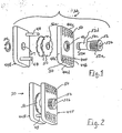
- the spreader clamp units each have a pair of spreader plates held in alignment by dowels and are caused to move apart by action of a screw element which is threaded through one of the spreader plates and passes freely through the other by way of a nonthreaded stem portion of reduced diameter originating at an annular stop shoulder and having an annular groove adjacent its other end.
- Spring washers are positioned between the stop shoulder and the nonthreaded spreader plate.
- the spreader clamp is held in assembled relation by a C-element fitting into the annular groove in the stem portion of the screw.
- the screw element of the spreader clamps used to mount the slide bolt and anchor hook units also passes throuh a mounting bracket or plate on the units which is located between the nonthreaded spreader plate and the spring washers and does not restrict clockwise turning of the spreader plates relative to the units.
- the spreader plates are shaped to pass through the accessways when held in an entry position and to extend into the channel grooves for the full depth thereof when turned about eighty degrees from the entry position into an operative position.
- Continued turning of the screw element then causes the spreader plates to move apart and firmly engage the side walls of the channel grooves.
- This spreading action results in compression of the spring washers.
- the clamping action of the spreader plates helps to vertically align the wall panels but does not pull the wall panels toward one another or push them apart.
- the compressed spring washers maintain a firm gripping action by the spreader plates under varying conditions such, for example, as thermal changes.
- the present invention incorporates a ceiling structure 20 having ceiling rails 21, a floor structure 22 having floor rails 23, and nonbearing wall structures including side-by-side panels 25.
- the ceiling structure 20 is supported in parallel spaced relationship to the floor structure as part of a weather shell structure 24 providing a foundation, roof, roughed-in utilities, and suitable external load-bearing columns 24a or narrow wall sections 24b which are preferably situated such as to limit only to a minor extent the locations of outside walls, doors and windows and leave the interior floor area unrestricted as to layout.
- the floor structure 22 may comprise a floor system with removable floor panels mounted on pedestals in a plenum containing wiring, plumbing, and ducts.
- the ceiling structure 20 may comprise a ceiling system with removable ceiling panels giving access to an overhead plenum.
- the wall panels 25 interfit with the floor rails 23 and are provided with ceiling lock assemblies 26 engaging the ceiling rails 21, and floor lock assemblies 28 having a hooking engagement with the floor rails 23.
- the wall panels are preferably used in conjunction with corner units 27.
- panel gripping units 30 Basic to both the ceiling and floor lock assemblies are panel gripping units 30 which are also used independently as alignment clamps.
- the wall panels 25 are precision molded by well-known laid-up, twin-sheet or blow-molding techniques resulting in a rigid unit having a durable skin 25a enclosing a foam core 25b having good insulating and sound-absorbing characteristics.
- Each panel 25 is formed along each of its two vertical side edges with a channel groove 32 located between coplanar side edge faces 25c, 25d and is formed along its bottom edge with a positioning groove 34.
- the top edge of the panels may also be grooved.
- the vertical edge faces 25c, 25d may be interrupted by vertical keeper grooves 33.
- the panels for exterior walls, designated 25x are preferably thicker than those for interior walls, with the add-on thickness being on the exterior (outdoor facing) side and forming outer lips 25e along the vertical edges which have longitudinal edge faces 25f and extend for the full height of the panels 25x.
- the floor rails 23x and top and bottom positioning grooves 34x formed in the exterior walls are preferably wider than the floor rails 23 and grooves 34 for the interior panels 34.
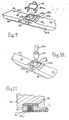
- the exterior and interior floor rails 23, 23x may be identical. They each have a generally rectangular, transverse cross section with an upper side formed with end positioning ledges 23a which are stepped above the level of an intermediate section 23b at sloped retaining shoulders 23c.
- the wall panels are internally recessed at the intersection of the channel grooves 32 and positioning grooves 34 to provide vertical sloped shoulders 25g which complement in slope and spacing that of the positioning shoulders 23c of the floor rails 23.
- the total length of each floor rail 23, 23x is the same as an established panel module and is maintained during production. In this regard, the horizontal distance between the lip edge faces 25f of each exterior panel 25x would be made slightly less than the panel module so that there will be a narrow exterior gap 36 between adjoining panels 25x for weather stripping.
- the floor rails 23, 23x be formed with a row of countersunk vertical holes 23d to receive nails or screws for attachment to the underlying floor structure.
- One or both of the side faces 23h of the floor rails 23, 23x are formed at their ends with horizontal anchor slots 38 to receive the floor lock assemblies 28.
- the anchor slots 38 preferably slope upwardly within the floor rails. It will be apparent that the floor rails 23, 23x may be made to a length equal to multiple of the panel modules, in which case the resulting interior ledges 23a would have double width longitudinally of the rails. There is no need for the ceiling rails 21 to be modular in length.
- the floor rail sections are fastened to the floor unit, the end ledges 23a thereof are each provided with a transverse slot 23e adjacent the shoulder 23c and a pair of shallower longitudinal slots 23f extending from the ends of the transverse slot to the respective end of the floor rail section.
- These slots 23e, 23f of adjoining floor rail sections are adapted to receive a wire spring clip 39 having depending U-sections 39a at its ends joined by tension links 39b.
- the U-sections are shaped to occupy the transverse slots 23e at adjoining ends of the two floor rail sections and the tension links 39b are located to occupy the related longitudinal slots 23f.
- the spacing of the tranverse slots 23e slightly exceeds the length of the tension links 39b so that they will be tensioned when the U-sections 39a are pressed downwardly into the transverse slots 23e.
- the ends of the floor rail sections have semicylindrical recesses 23g at their ends so that two end-to-end floor rail sections provide a cylindri cal pocket for receiving a cup gasket 41.
- This cup gasket is pressed firmly into sealing relation with the related floor rail sections and underlying weatherstripping by use of a rigid tapered plug 41a which is forced downwardly within the cup gasket.
- the adjoining side edge faces 25c-25c and 25d-25d are spaced apart to provide respective accessways 42 at opposite sides of the panels which give access to the corresponding grooves 32.
- the adjoining side edge faces 25c-25c are spaced apart to provide an accessway 42x at the indoor side of the panels.
- the lips 25c on the exterior side of the panel 25x block the outer end of the space between side edge faces 25d of adjoining exterior panels 25x so that it functions as an extension 43 of accessway 42x.
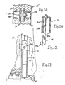
- the panel gripping units 30 include a pair of front and back clamping plates 44F, 44B with outside gripping faces 44a which are preferably formed with gripping teeth 44b or other suitable gripping elements for engaging and gripping the opposite side faces 32a, 32b of the vertical panel grooves 32 in the interior or exterior panels.
- the front plate 44F has a central threaded bore 46 which aligns with a central bore 47 of lesser diameter in the back plate 44B.
- Alignment means is provided in the form of a pair of diagonally opposite dowels 48 projecting forwardly from the back plate 44B to register with holes 50 through the front plate 44F.
- Each gripping unit 30 is completed by a screw 52, C-ring 54, and a pair of Belleville spring washers 56.
- the screw 52 has a threaded head portion 52a formed at its forward end with a flat-sided recess 52b for receiving a complementing tool.
- the opposite end of the screw 52 is preferably also recessed to receive a suitable screw driver.
- Behind the head portion 52a the screw 52 is stepped at a shoulder 52c to a rear stem portion 52d which is formed with an annular groove adjacent its rear end for receiving the C-ring 54.
- the screw may be passed rearwardly through the bore 46 in the front plate 44F and screwed into the bore 46 only partway along the length of the threaded portion 52a. Then the screw is passed through center openings 56a in the spring washers and through the bore 47 in the back plate 44B, while the dowels 48 are registered with the front openings 50.
- the spring washers 56 are then confined on the stem portion 52d between the shoulder 52e and the front face of the back plate 44B, and the rear portion of the stem portion projects rearwardly behind the back plate 44B sufficiently to expose the groove 52c so that the C-ring 54 can be applied thereto to hold the assembly together.
- Clamping plates 44F, 44B are generally a parallelogram in shape and the width thereof between longitudinal edges 44a, 44b is less than the width of the accessways 42, 43, whereas the length thereof between end edges 44c, 44d measured parallel to the longitudinal edges 44a, 44b exceeds the width of the accessways 42, 43. It will also be noted that the two diagonally opposite apexes 44e, 44f of the plates 44F, 44B, which are in the lead when the gripping unit 30 is turned clockwise as viewed from the front, are the closer of the four apexes to the center of the plates 44F, 44B and have their noses rounded.
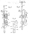
- a pair of the clamping units 30 are used as part of each ceiling lock assembly 26 and one of the clamping units is incorporated in each anchoring unit 28.
- a ceiling lock assembly it is seen that it has a mounting bracket 58 and a slide bolt 60.
- the mounting bracket 58 comprises an elongated vertical plate 58a having horizontal top and bottom flanges 58b, 58c with aligned openings 58h, 58i for receiving the slide bolt 60.
- C-rings 59 filling into annular grooves in the slide keep the slide bolt and bracket 58 in assembled relation before and during installation.
- the mounting plate 58a and bottom flange 58c are narrower than the accessways between panels so that they can pass therethrough, and the top flange 58b is preferably wider than the mounting plate 58 and accessways so that it can rest on top of adjoining panels.
- the mounting plate 58 is formed with vertically staggered pairs of notches 58d, 58e.
- the mounting plate also has a pair of central openings 58f, 58g located midway between the two notches of each pair of notches.
- the spacing and arrangement of the notches 58d, 58e and openings 58f correspond to those of the dowels 48 and central opening 47 in the back plates 44B of the clamping units 30 so that the dowels can occupy the notches when a pair of the clamping units are mounted on the mounting bracket 58, with their screws passing through the bracket openings 58f, 58g and the mounting plate 58a positioned between the back clamping plate 44B and spring washers 56 of each clamping unit.
- the spacing between the shoulder 52d and annular groove 52a of the clamping screws 52 is increased by the thickness of the mounting plate 58a.
- the arrangement of the pairs of notches 58d, 58e is such that the clamping units can be turned clockwise relative to the mounting bracket 58.
- the slide bolt 60 has a spherical head 60a adapted to have a snap interfit with a central locking channel 62 extending along the ceiling rail and having opposed bottom gripping lips 62a.
- the head of the slide bolt can be given a cross section similar to that of the locking channel 62, and the locking channel can be given a suitable cross section similar to that of the head 60a.
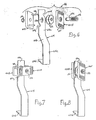
- each has a hook plate 64 formed with an upper vertical mounting section 64a, a forwardly sloped central section 64b, a front vertical section 64c, and a bottom, upwardly sloping, terminal hook section 64d adapted to fit into adjoining anchor slots 38 of floor rail sections 23.
- the upper mounting section 64a is formed with a central slot 64e and notches 64f, 64g in its opposite edges.
- the hook plate 64 receives one of the clamping units 30, with the screw passing through the slot 64e and the mounting section 64a located between the back clamping plate 44B and the spring washers 56.
- the dowels 48 of the clamping unit occupy the notches 64f, 64g when the length of the clamping plates 44F, 44B is aligned with the length of the hook plate 64.
- the arrangement of the notches permits the clamping plates to then be turned clockwise relative to the hook plate.
- a floor lock assembly 28 can be inserted through the accessway between two adjoining wall panels and the hook 64d fitted into the anchor slots 38 of the underlying floor rail sections preparatory to locking the clamping unit 30 of the floor lock assembly in place by turning its screw 52.
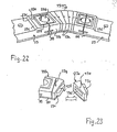
- the building structure non-load-bearing interior and exterior corner units 27, 27x comprising molded intermediate sectors 71 and end sections 72 connected together at weatherproof joints.
- the end sectors have their outer longitudinal end walls formed to the same configuration as the vertical side edges of the wall panels 25 so that the panels adjoining the corner units can be secured to the corner post by clamping units 30 and to the floor and ceiling rails by ceiling and floor lock assemblies 26, 28 at the joints between the corner post units and the adjoining wall panels.
- the number of intermediate sectors 71 can be varied to vary the corner angle.
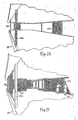
- the corner units 27, 27x are basically the same except that in the case of the interior corners, the longitudinal end walls will be narrower to match in size and configuration the vertical side edges of the interior wall panels 25. It is preferred to provide curved floor rail sections 73 (Figure 21) to fit between the ends of the straight floor rail sections 23 adjoining the corners and to provide the lower ends of the corner units 27, 27x with grooves to interfit with these corner curved floor rail sections 73 in the same manner as the wall panels interfit with the other floor rail sections 23.
- the curved floor rail sections 73 may be molded as a single piece or may comprise multiple intermediate segments 73a fitting between end pieces 73b.
- Each intermediate segment 73a encompasses an angle module, such as, for example, 71 ⁇ 2 or 15 degrees, so that multiple of the segments can be selected to form the desired corner angle.
- the segments 73a each present a tongue 73c at one side and a matching socket 73d at the opposite side for interfitting the segments. Alternate of the pieces 73b are formed at their inner end with a tongue 73c or socket 73d to interfit with the selected intermediate segments 73a.
- Mating vertical holes 73e, 73f are provided for passing nails 73g through the tongues 73c and into the underlying floor structure.
- the accessways between the wall panels may be covered by trim strips 74, which have longitudinal feet 74a which snap-fit into the grooves 33.
- the accessways can also house mounting channels 76 for holding shelf or cabinet brackets, for example.
- Each mounting channel 76 has a back T-slot 76a for slidably receiving clips 78, having a handle 78a at one end and an opening 78b at its other end for fitting over the screw 52 of one of the clamping units 30.
- the back wall of the mounting channel 76 is formed with openings 76b for receiving the head end portion of the screw 52 of clamps 30.
- a mounting channel 76 can be connected by clips 78 to two or more clamping units 30, and then the mounting channel 76, clips 78 and clamping units 30 can be inserted as a unit into one of the accessways whie the clamping units have the longer dimension of their clamping plates 44F, 44B extending vertically. Then the clamping units 30 can be turned and engaged with the wall panels in the same manner as previously described by turning the screws 52, which are accessible through the front of the mounting channel.
- Suitable weatherstripping gaskets 80, 81 are placed between the floor rail sections 25, 73 and the underlying floor structure and between the bottom edge of the wall panels 25 and the top of the floor rail sections. Also, suitable moisture-resistant insulation is placed between the tops of the external wall panels 25x and the ceiling rails, and in the extensions 43 of the accessways 42x of the exterior wall panels. Gaskets may also be placed between the opposed joint faces 25f of adjoining exterior wall panels.
- the layout for the floor rail sections 23, 73 is planned and marked, and preferably is computer justified.
- the installation steps are then as follows:
Landscapes
- Engineering & Computer Science (AREA)
- Architecture (AREA)
- Physics & Mathematics (AREA)
- Electromagnetism (AREA)
- Civil Engineering (AREA)
- Structural Engineering (AREA)
- Finishing Walls (AREA)
- Connection Of Plates (AREA)
- Conveying And Assembling Of Building Elements In Situ (AREA)
- Residential Or Office Buildings (AREA)
- Joining Of Building Structures In Genera (AREA)
- Building Environments (AREA)
Applications Claiming Priority (2)
| Application Number | Priority Date | Filing Date | Title |
|---|---|---|---|
| US07/208,896 US4899510A (en) | 1988-06-17 | 1988-06-17 | Building enclosure system and method |
| US208896 | 1988-06-17 |
Publications (2)
| Publication Number | Publication Date |
|---|---|
| EP0346902A2 true EP0346902A2 (de) | 1989-12-20 |
| EP0346902A3 EP0346902A3 (de) | 1990-06-13 |
Family
ID=22776483
Family Applications (1)
| Application Number | Title | Priority Date | Filing Date |
|---|---|---|---|
| EP89110890A Withdrawn EP0346902A3 (de) | 1988-06-17 | 1989-06-15 | System und Verfahren für Gebäudezwischenwände |
Country Status (6)
| Country | Link |
|---|---|
| US (2) | US4899510A (de) |
| EP (1) | EP0346902A3 (de) |
| JP (1) | JP2524639B2 (de) |
| KR (1) | KR910001195A (de) |
| AU (1) | AU621377B2 (de) |
| CA (1) | CA1326120C (de) |
Cited By (2)
| Publication number | Priority date | Publication date | Assignee | Title |
|---|---|---|---|---|
| EP0434433A3 (en) * | 1989-12-21 | 1992-11-19 | Olivetti Synthesis S.P.A. | Panel connecting arrangement |
| US7395634B2 (en) * | 2003-03-31 | 2008-07-08 | Suncast Corporation | Plastic expandable utility shed |
Families Citing this family (46)
| Publication number | Priority date | Publication date | Assignee | Title |
|---|---|---|---|---|
| US5172529A (en) * | 1991-01-22 | 1992-12-22 | Herman Miller, Inc. | Hinged wire management cover panel |
| WO1993018250A1 (en) * | 1992-03-05 | 1993-09-16 | Bockmiller Douglas F | Wall assembly support apparatus |
| JP2995607B2 (ja) * | 1994-04-15 | 1999-12-27 | エムベーアー−デザイン・ウント・デイスプレイ・プロドウクト・ゲゼルシヤフト・ミツト・ベシユレンクテル・ハフツング | 間仕切り壁 |
| US6637173B1 (en) | 1996-01-26 | 2003-10-28 | Flex-Ability Concepts, L.L.C. | Apparatus and methods of forming a curved structure |
| US6000181A (en) * | 1996-01-26 | 1999-12-14 | Flex-Ability Concepts, L.L.C. | Apparatus and methods of forming a curved structure |
| US6047508A (en) * | 1998-03-10 | 2000-04-11 | Steelcase Development Inc. | Wall panel partition system |
| US7210271B2 (en) * | 2002-09-17 | 2007-05-01 | Flexability Concepts Llc | Header apparatus and method for a structural framing system |
| US7137227B2 (en) * | 2003-07-27 | 2006-11-21 | Robert Michael Franz | Structural brace |
| ATE536448T1 (de) * | 2003-10-27 | 2011-12-15 | Radius Track Corp | Strukturausrichtungsglied |
| KR100513152B1 (ko) * | 2005-05-12 | 2005-09-08 | 경일산업 주식회사 | 건축판재 레일식 고정구 및 그를 이용한 건축판재 부착방법 |
| CA2656542C (en) * | 2006-06-28 | 2012-08-28 | Flex-Ability Concepts, L.L.C. | Apparatus and methods of forming a curved structure |
| US7832154B2 (en) * | 2006-09-18 | 2010-11-16 | Geoff Gosling | Position retention mechanism for modular wall assembly |
| IE20070819A1 (en) * | 2006-11-22 | 2008-07-23 | Nora C Hurley | Pre-fabricated construction system |
| US20080246375A1 (en) * | 2007-04-03 | 2008-10-09 | Berg Neil M | Security cabinet |
| US10563399B2 (en) | 2007-08-06 | 2020-02-18 | California Expanded Metal Products Company | Two-piece track system |
| US10619347B2 (en) | 2007-08-22 | 2020-04-14 | California Expanded Metal Products Company | Fire-rated wall and ceiling system |
| US8671632B2 (en) * | 2009-09-21 | 2014-03-18 | California Expanded Metal Products Company | Wall gap fire block device, system and method |
| US10184246B2 (en) | 2010-04-08 | 2019-01-22 | California Expanded Metal Products Company | Fire-rated wall construction product |
| US8099922B2 (en) * | 2010-06-08 | 2012-01-24 | Cablofil, Inc. | Assemblies for constructing solar panel mounting systems |
| US10077550B2 (en) | 2012-01-20 | 2018-09-18 | California Expanded Metal Products Company | Fire-rated joint system |
| US12215498B2 (en) | 2012-01-20 | 2025-02-04 | Cemco, Llc | Fire-rated joint system |
| CA2881683C (en) | 2012-09-17 | 2018-07-24 | Steelcase Inc. | Floor-to-ceiling partition wall assembly |
| US9493941B2 (en) * | 2013-05-02 | 2016-11-15 | Donald George White | Thermal break wall systems and thermal adjustable clip |
| US9151063B2 (en) | 2013-10-25 | 2015-10-06 | Mbrico, Llc | Tile and support structure |
| US10041254B2 (en) | 2013-10-25 | 2018-08-07 | Mbrico, Llc | Tile and support structure |
| US11199007B2 (en) * | 2013-10-25 | 2021-12-14 | Mbrico, Llc | Tile and support structure |
| US11371245B2 (en) | 2013-10-25 | 2022-06-28 | Mbrico, Llc | Tile and support structure |
| US10988931B1 (en) | 2013-10-25 | 2021-04-27 | Mbrico, Llc | Tile and support structure |
| US12595658B2 (en) | 2013-10-25 | 2026-04-07 | Mbrico, Llc | Tile and support structure for vertical mounting tiles |
| USD839078S1 (en) | 2018-01-04 | 2019-01-29 | Clarkwestern Dietrich Building Systems Llc | Slide clip |
| US10753084B2 (en) | 2018-03-15 | 2020-08-25 | California Expanded Metal Products Company | Fire-rated joint component and wall assembly |
| US10689842B2 (en) | 2018-03-15 | 2020-06-23 | California Expanded Metal Products Company | Multi-layer fire-rated joint component |
| US11162259B2 (en) | 2018-04-30 | 2021-11-02 | California Expanded Metal Products Company | Mechanically fastened firestop flute plug |
| US11111666B2 (en) | 2018-08-16 | 2021-09-07 | California Expanded Metal Products Company | Fire or sound blocking components and wall assemblies with fire or sound blocking components |
| US10914065B2 (en) | 2019-01-24 | 2021-02-09 | California Expanded Metal Products Company | Wall joint or sound block component and wall assemblies |
| US11268274B2 (en) | 2019-03-04 | 2022-03-08 | California Expanded Metal Products Company | Two-piece deflection drift angle |
| US11982087B2 (en) | 2019-05-17 | 2024-05-14 | Mbrico, Llc | Tile and support structure |
| US11920343B2 (en) | 2019-12-02 | 2024-03-05 | Cemco, Llc | Fire-rated wall joint component and related assemblies |
| USD959251S1 (en) | 2020-07-22 | 2022-08-02 | Clarkwestern Dietrich Building Systems Llc | Slide clip |
| US11692340B2 (en) | 2020-07-22 | 2023-07-04 | Clarkwestern Dietrich Building Systems Llc | Slide clip |
| USD959250S1 (en) | 2020-07-22 | 2022-08-02 | Clarkwestern Dietrich Building Systems Llc | Slide clip |
| US12454824B2 (en) | 2020-08-19 | 2025-10-28 | Cemco, Llc | Building joint with compressible firestopping component |
| EP4200490B1 (de) * | 2020-08-24 | 2025-10-01 | Hilti Aktiengesellschaft | Dichtvorrichtung für randfuge sowie trockenbauwand |
| US12392131B2 (en) * | 2020-08-24 | 2025-08-19 | Hilti Aktiengesellschaft | Sealing profile and drywall |
| CN112922140B (zh) * | 2021-01-26 | 2022-04-12 | 成都中品建设工程有限公司 | 一种模块化集成房屋建造施工方法 |
| US12607009B2 (en) | 2021-12-27 | 2026-04-21 | Cemco, Llc | Fire-rated gaskets and wall assemblies |
Family Cites Families (13)
| Publication number | Priority date | Publication date | Assignee | Title |
|---|---|---|---|---|
| US1681311A (en) * | 1928-02-09 | 1928-08-21 | Ewald F Techmer | Wall construction |
| US3189135A (en) * | 1959-05-11 | 1965-06-15 | Nat Gypsum Co | Demountable partition |
| FR82442E (fr) * | 1962-10-12 | 1964-02-07 | Cloison métallique | |
| FR1412391A (fr) * | 1964-02-03 | 1965-10-01 | Jaz Sa | Diapason de torsion |
| US3431692A (en) * | 1966-12-05 | 1969-03-11 | Carl R Freeman | Building construction |
| US3603049A (en) * | 1969-08-18 | 1971-09-07 | William C Pierce | Wall panel construction and assembly including improved edge and bottom sealing |
| FR2069883B2 (de) * | 1969-11-28 | 1973-03-16 | Lafaye Michel | |
| US3805471A (en) * | 1970-11-19 | 1974-04-23 | Perfect Module Sys Inc | Building panel construction system |
| CH554464A (fr) * | 1973-09-04 | 1974-09-30 | Design & Projets Sa | Cloison amovible. |
| GB1502869A (en) * | 1975-12-24 | 1978-03-08 | Iberica Del Frio Sa | Wall construction |
| FR2378912A1 (fr) * | 1977-01-26 | 1978-08-25 | Pollet Sa | Cloison amovible ou demontable et elements constitutifs de ladite cloison |
| US4450658A (en) * | 1982-01-11 | 1984-05-29 | Hauserman, Inc. | Unitized partition wall system |
| AU573885B2 (en) * | 1985-08-21 | 1988-06-23 | Antonino Gioia | Panel edge fastener |
-
1988
- 1988-06-17 US US07/208,896 patent/US4899510A/en not_active Expired - Lifetime
-
1989
- 1989-06-13 CA CA000602574A patent/CA1326120C/en not_active Expired - Lifetime
- 1989-06-15 AU AU36450/89A patent/AU621377B2/en not_active Ceased
- 1989-06-15 EP EP89110890A patent/EP0346902A3/de not_active Withdrawn
- 1989-06-16 JP JP1154382A patent/JP2524639B2/ja not_active Expired - Lifetime
- 1989-06-16 KR KR1019890008290A patent/KR910001195A/ko not_active Withdrawn
-
1990
- 1990-02-12 US US07/478,311 patent/US5090170A/en not_active Expired - Lifetime
Cited By (2)
| Publication number | Priority date | Publication date | Assignee | Title |
|---|---|---|---|---|
| EP0434433A3 (en) * | 1989-12-21 | 1992-11-19 | Olivetti Synthesis S.P.A. | Panel connecting arrangement |
| US7395634B2 (en) * | 2003-03-31 | 2008-07-08 | Suncast Corporation | Plastic expandable utility shed |
Also Published As
| Publication number | Publication date |
|---|---|
| JPH02120440A (ja) | 1990-05-08 |
| CA1326120C (en) | 1994-01-18 |
| US5090170A (en) | 1992-02-25 |
| AU3645089A (en) | 1989-12-21 |
| EP0346902A3 (de) | 1990-06-13 |
| AU621377B2 (en) | 1992-03-12 |
| JP2524639B2 (ja) | 1996-08-14 |
| US4899510A (en) | 1990-02-13 |
| KR910001195A (ko) | 1991-01-30 |
Similar Documents
| Publication | Publication Date | Title |
|---|---|---|
| US4899510A (en) | Building enclosure system and method | |
| US5288041A (en) | Electrical junction box mounting bracket device and method | |
| US7043884B2 (en) | Cladding system | |
| US5694729A (en) | Wall partition connector | |
| EP0400804B1 (de) | Wandsystem | |
| US5224673A (en) | Electrical junction box mounting bracket device and method | |
| US10294676B2 (en) | Support bracket assembly and method | |
| US9447585B2 (en) | Support bracket apparatus | |
| US4398841A (en) | Column-to-beam connector | |
| US20190024381A1 (en) | Support bracket apparatus | |
| US6061991A (en) | Deck system | |
| US5904022A (en) | Aesthetic post and beam construction having modular parts | |
| US11118358B2 (en) | Support bracket assembly and method | |
| OA10128A (en) | Element based foam and concrete modular wall construction and method and apparatus therefor | |
| EP0570374B1 (de) | Rahmen für teilungswände | |
| CA2888404C (en) | Support bracket apparatus | |
| CA2872780A1 (en) | Support bracket apparatus | |
| RU2317764C2 (ru) | Система, зажимной элемент и запирающий элемент для соединения профильных элементов | |
| US5012625A (en) | Building enclosure system and method | |
| CA2872778C (en) | Support bracket assembly and method | |
| US4388790A (en) | Partition and paneling system | |
| US12584325B2 (en) | Flexible corner for a temporary wall system | |
| US20250129607A1 (en) | Modular Decking System | |
| JPH0539644A (ja) | 建築囲い装置および方法 | |
| KR200156961Y1 (ko) | 칸막이용 높이조절식 걸레받이 |
Legal Events
| Date | Code | Title | Description |
|---|---|---|---|
| PUAI | Public reference made under article 153(3) epc to a published international application that has entered the european phase |
Free format text: ORIGINAL CODE: 0009012 |
|
| AK | Designated contracting states |
Kind code of ref document: A2 Designated state(s): AT BE CH DE ES FR GB GR IT LI LU NL SE |
|
| PUAL | Search report despatched |
Free format text: ORIGINAL CODE: 0009013 |
|
| RHK1 | Main classification (correction) |
Ipc: E04B 2/74 |
|
| AK | Designated contracting states |
Kind code of ref document: A3 Designated state(s): AT BE CH DE ES FR GB GR IT LI LU NL SE |
|
| 17P | Request for examination filed |
Effective date: 19900824 |
|
| 17Q | First examination report despatched |
Effective date: 19910301 |
|
| STAA | Information on the status of an ep patent application or granted ep patent |
Free format text: STATUS: THE APPLICATION IS DEEMED TO BE WITHDRAWN |
|
| 18D | Application deemed to be withdrawn |
Effective date: 19920714 |