EP0346819A2 - Method and apparatus for the contactless measuring and optionally machining of surfaces - Google Patents
Method and apparatus for the contactless measuring and optionally machining of surfaces Download PDFInfo
- Publication number
- EP0346819A2 EP0346819A2 EP89110657A EP89110657A EP0346819A2 EP 0346819 A2 EP0346819 A2 EP 0346819A2 EP 89110657 A EP89110657 A EP 89110657A EP 89110657 A EP89110657 A EP 89110657A EP 0346819 A2 EP0346819 A2 EP 0346819A2
- Authority
- EP
- European Patent Office
- Prior art keywords
- contour
- reference element
- measuring
- machining
- processing
- Prior art date
- Legal status (The legal status is an assumption and is not a legal conclusion. Google has not performed a legal analysis and makes no representation as to the accuracy of the status listed.)
- Withdrawn
Links
Images


Classifications
-
- B—PERFORMING OPERATIONS; TRANSPORTING
- B24—GRINDING; POLISHING
- B24B—MACHINES, DEVICES, OR PROCESSES FOR GRINDING OR POLISHING; DRESSING OR CONDITIONING OF ABRADING SURFACES; FEEDING OF GRINDING, POLISHING, OR LAPPING AGENTS
- B24B49/00—Measuring or gauging equipment for controlling the feed movement of the grinding tool or work; Arrangements of indicating or measuring equipment, e.g. for indicating the start of the grinding operation
- B24B49/02—Measuring or gauging equipment for controlling the feed movement of the grinding tool or work; Arrangements of indicating or measuring equipment, e.g. for indicating the start of the grinding operation according to the instantaneous size and required size of the workpiece acted upon, the measuring or gauging being continuous or intermittent
- B24B49/04—Measuring or gauging equipment for controlling the feed movement of the grinding tool or work; Arrangements of indicating or measuring equipment, e.g. for indicating the start of the grinding operation according to the instantaneous size and required size of the workpiece acted upon, the measuring or gauging being continuous or intermittent involving measurement of the workpiece at the place of grinding during grinding operation
-
- B—PERFORMING OPERATIONS; TRANSPORTING
- B24—GRINDING; POLISHING
- B24B—MACHINES, DEVICES, OR PROCESSES FOR GRINDING OR POLISHING; DRESSING OR CONDITIONING OF ABRADING SURFACES; FEEDING OF GRINDING, POLISHING, OR LAPPING AGENTS
- B24B13/00—Machines or devices designed for grinding or polishing optical surfaces on lenses or surfaces of similar shape on other work; Accessories therefor
- B24B13/015—Machines or devices designed for grinding or polishing optical surfaces on lenses or surfaces of similar shape on other work; Accessories therefor of television picture tube viewing panels, headlight reflectors or the like
Definitions
- Scanning heterodyne interferometers are preferably used as interferometer measuring devices, which work with two closely adjacent wavelengths. The wavelength relationships correspond to a beat. Such heterodyne interferometers are particularly suitable because they are relatively insensitive to surface roughness.
- the invention enables the measurement and shaping of large-area, also non-rotationally symmetrical aspheres with a contour accuracy better than 25 nm.
- the invention is of striking conceptual simplicity, since it requires a minimum of axes, does not make any extraordinary demands on the accuracy of the axes, and extensive control of the processing tools with regard to pressure, speed, alignment and infeed is not necessary.
- the susceptibility to faults is low due to the high redundancy in the measuring devices, which, together with the possibility of self-checking and error detection, ensures great operational reliability.
- Several individual parts for example several mirror bodies of a segment mirror, can be measured simultaneously and possibly processed.
- the measuring or machining process does not have to be interrupted to enable the inspection and control of the surface quality; the workpiece does not have to be removed from the device will.
- the invention thus enables a very quick and very economical measurement and, if necessary, processing.
- a reference element 26 extends parallel, as shown in FIG. 4, which is formed, for example, by a polished Zerodur ruler.
- the reference element 26 is suspended a few millimeters above the surface 34 of the mirror segment 20, and is supported in the exemplary embodiment by the supports for the guide track 24, which rise on the one hand near the axis of rotation and on the other hand on the outer circumference of the measuring machine 10 from the base frame 12.
- the polishing head 30 is driven and adjusted by devices known in the prior art; an encoder (not shown), which extends along the guideway 32 and which can also be formed by a glass scale, enables the respective radial position of the polishing head 30 to be determined.
- the polishing head 30 is always at the same distance on the basis of the data stored in the computer to the axis of rotation 15 (center of the rotary table) held like the associated interferometer measuring head 28, d. H. the measuring head of the measuring device 16 preceding in the machining direction A (FIG. 7).
- the polishing pins of the polishing heads 30 are placed on or lifted from the surface by computer control.
- the processing pressure of the polishing pins on the surface is adjusted so that the material removal between two interferometer positions is at most equal to the permissible contour tolerance (e.g. 25 nm).
- the measuring and machining processes are repeated until all mirror segments have reached the target surface contour within the tolerance.
- fillers can be used and also polished.
Abstract
Die Erfindung betrifft Verfahren zur berührungslosen Vermessung und ggf. abtragenden Bearbeitung von Oberflächen, insbesondere von großflächigen Spiegeln oder dergleichen, bei dem zur Ermittlung von Konturabweichungen der Oberfläche die Differenz zwischen interferometrisch erfaßten Oberflächenkontur-Istwerten und vorgewählten Oberflächenkontur-Sollwerten bestimmt wird. Erfindungsgemäß wird eine Bezugskontur wenigstens eines Referenzelements, deren Erstreckung einem Vermessungs-und ggf. Bearbeitungsbereich der Oberfläche im wesentlichen entspricht, interferometrisch bezüglich eines Normals vermessen, dessen Geometrie innerhalb der zulässigen Konturtoleranz der Oberfläche bekannt ist. Die zu vermessende Oberfläche wird in eine definierte räumliche Lage bezüglich des Referenzelementes gebracht, die Beabstandung der Bezugskontur vom Vermessungs- bzw. Bearbeitungsbereich der Oberfläche wird inkrementell interferometrisch erfaßt und die jeweilige Differenz zwischen Ist- und Sollwert wird bestimmt. Für die Bearbeitung wird ggf. ein Materialabtrag von der Oberfläche vorgenommen, dessen Ausmaß die zulässige Konturtoleranz nicht übersteigt. Außerdem betrifft die Erfindung Vorrichtungen zur Durchführung dieser Verfahren.The invention relates to methods for contactless measurement and, if necessary, machining of surfaces, in particular of large mirrors or the like, in which the difference between interferometrically recorded actual surface contour values and preselected desired surface contour values is determined in order to determine contour deviations of the surface. According to the invention, a reference contour of at least one reference element, the extent of which essentially corresponds to a measurement and, if appropriate, processing area of the surface, is measured interferometrically with respect to a standard, the geometry of which is known within the permissible contour tolerance of the surface. The surface to be measured is brought into a defined spatial position with respect to the reference element, the spacing of the reference contour from the measurement or processing area of the surface is recorded incrementally interferometrically and the respective difference between the actual and target value is determined. For machining, material may be removed from the surface, the extent of which does not exceed the permissible contour tolerance. The invention also relates to devices for carrying out these methods.
Description
Die Erfindung betrifft Verfahren zur berührungslosen Vermessung und ggf. abtragenden Bearbeitung von Oberflächen, insbesondere zum Feinstpolieren großflächiger Spiegel oder dergleichen, bei dem die Differenz zwischen interferometrisch erfaßten Oberflächenkontur-Istwerten und vorgewählten Oberflächenkontur-Sollwerten bestimmt und ggt. in Abhängigkeit vom Ergebnis ein oberflächiger Materialabtrag vorgenommen wird.The invention relates to methods for non-contact measurement and, if necessary, machining of surfaces, in particular for fine polishing of large-area mirrors or the like, in which the difference between interferometrically recorded actual surface contour values and preselected desired surface contour values is determined and given. depending on the result, a superficial material removal is carried out.
Außerdem betrifft die Erfindung zur Durchführung dieser Verfahren geeignete Vorrichtungen.The invention also relates to devices suitable for carrying out these methods.
Bekannte Bearbeitungsverfahren dienen zur Erzeugung von Oberflächen mit hochgradiger Formtreue auch bei großen Oberflächen. Anwendung finden diese Verfahren beispielsweise bei der Herstellung von Reflexionsoptiken, insbesondere für die Astronomie; ein Beispiel bilden Teleskopspiegel für den sichtbaren und infraroten Spektralbereich.Known machining processes are used to produce surfaces with a high degree of shape accuracy, even with large surfaces. These methods are used, for example, in the manufacture of reflection optics, in particular for astronomy; one example are telescope mirrors for the visible and infrared spectral range.
Die formtreue Herstellung insbesondere großflächiger Werkstücke bietet besondere Schwierigkeiten. Dies gilt schon dann, wenn die Oberfläche plan, sphärisch oder rotationssymmetrisch asphärisch (beispielsweise parabolförmig) ist. Erst recht gilt dies für nicht-rotationssymmetrische asphärische Oberflächen; für die Erzeugung solcher Oberflächen gab es bislang kein befriedigendes Verfahren.The true-to-shape production of large workpieces in particular presents particular difficulties. This applies even if the surface is flat, spherical or rotationally symmetrical aspherical (for example parabolic). This is especially true for non-rotationally symmetrical aspherical surfaces; To date, there has been no satisfactory method for producing such surfaces.
Dabei werden insbesondere im Bereich der Astronomie solche Werkstücke dringend benötigt. Spezieller betrifft dies das bestehende Bedürfnis, nicht-rotationssymmetrische asphärische Segmentspiegel für Großteleskope mit Öffnungen von mehreren Metern ökonomisch herstellen zu können.Such workpieces are urgently needed, particularly in the field of astronomy. This applies in particular to the existing need to be able to economically produce non-rotationally symmetrical aspherical segment mirrors for large telescopes with openings of several meters.
Zur Herstellung solcher Spiegel folgte man bisher dem klassischen, von Herschel, Ritchey, Anderson und anderen entwickelten Verfahren. Dabei wird zunächst mit großflächigen Schleif- und Polierkörpern die best-angenäherte sphärische Form hergestellt; mit kleinen Läpp- und Polierscheiben werden sodann die verbliebenen Abweichungen zur Soll-Form beseitigt. Der Polierprozeß muß mehrfach durch Inspektionen der erreichten Ist-Form unterbrochen werden, wofür bis heute der Foucault-Test die zuverlässigste Prüfmethode darstellt.Up to now, the classic method developed by Herschel, Ritchey, Anderson and others has been used to produce such mirrors. First, the best approximated spherical shape is created with large-area grinding and polishing bodies; with small lapping and polishing discs, the remaining deviations from the target shape are then eliminated. The polishing process has to be interrupted several times by inspections of the actual shape achieved, for which the Foucault test is still the most reliable test method.
Aus der DE-PS 34 30 499 sind bereits ein Verfahren und eine Vorrichtung zur Erzeugung asphärischer Oberflächen bekannt. Dabei soll ein flexibles Läpp- oder Polierwerkzeug verwendet werden, welches im wesentlichen die gesamte zu bearbeitende Werkstückoberfläche gleichzeitig bedeckt und am Werkstück mit örtlich unterschiedlichen Drücken anliegt; die örtlichen Druckunterschiede sollen den Abweichungen der Werkstückoberfläche von der Soll-Form entsprechend gewählt werden. Realisiert wird dies durch eine Membran, die die gesamte Werkstückoberfläche bedeckt und werkstückseitig eine Vielzahl einzelner Bearbeitungskörper trägt. Von der anderen Seite her wird die Membran mitsamt den Bearbeitungskörpern durch einzeln steuerbare Druckschuhe gegen die Oberfläche gedrückt. Die Formtreue soll durch die Steuerung der einzelnen Druckschuhe hinsichtlich des Bearbeitungsdruckes sowie durch gelegentliche Vermessung des Werkstückes sichergestellt werden, wobei die Membran zwischen jedem Bearbeitungsvorgang etwa in Soll-Form der zu bearbeitenden Fläche gebracht wird. Dazu kann sie beispielsweise auf einem separaten Werkzeug abgedrückt werden, das etwa die Soll-Form der zu bearbeitenden Fläche besitzt.From DE-PS 34 30 499 a method and a device for producing aspherical surfaces are already known. In this case, a flexible lapping or polishing tool is to be used, which essentially covers the entire workpiece surface to be machined at the same time and is applied to the workpiece with locally different pressures; the local pressure differences should be chosen according to the deviations of the workpiece surface from the target shape. This is implemented by a membrane that covers the entire workpiece surface and carries a large number of individual machining bodies on the workpiece side. From the other side, the membrane together with the processing bodies is pressed against the surface by individually controllable pressure shoes. The form accuracy is to be ensured by controlling the individual pressure shoes with regard to the processing pressure and by occasional measurement of the workpiece, the membrane being brought into the shape of the surface to be processed between each processing operation. For this purpose, it can be pressed, for example, on a separate tool, which has approximately the desired shape of the surface to be machined.
Dieses Verfahren ist für die Herstellung größerer asphärischer Oberflächen (etwa ab 1m) wegen der dann über das erlaubte Toleranzband anwachsenden Unsicherheit des Meßsystems wenig geeignet.This method is not very suitable for the production of larger aspherical surfaces (about 1m or more) because of the uncertainty of the measuring system that then increases over the permitted tolerance band.
Aufgabe der Erfindung ist es, ein Verfahren zur berührungslosen Vermessung von Oberflächen, insbesondere von großflächigen Spiegeln o. dgl. zu schaffen, das eine exakte Vermessung beliebig geformter Oberflächen bei geringem Aufwand gestattet.The object of the invention is to create a method for the contactless measurement of surfaces, in particular of large mirrors or the like, which allows an exact measurement of surfaces of any shape with little effort.
Aufgabe der Erfindung ist es weiterhin, ein Verfahren und eine Vorrichtung zur abtragenden Bearbeitung von Oberflächen anzugeben, die es gestatten, auch große Oberflächen bei beliebiger, auch nicht-rotationssymmetrisch asphärischer, Gestalt formtreu herzustellen.It is also an object of the invention to provide a method and a device for the machining of surfaces which allow large surfaces to be produced true to shape with any shape, including non-rotationally symmetrical aspherical ones.
Dabei wird eine Formtreue angestrebt, die bezüglich des Werkstückdurchmessers Abweichungen von mehr als 3 x 10⁻⁸m ausschließt. Das bedeutet, daß bei einem Spiegeldurchmesser von 1m beispielsweise eine Formtreue erreicht wird, die besser als 30 Nanometer ist. Gleichzeitig soll eine Mikrorauhigkeit von weniger als 10 Å rms erreicht werden.In doing so, a form accuracy is sought, which excludes deviations of more than 3 x 10⁻⁸m with regard to the workpiece diameter. This means that with a mirror diameter of 1m, for example, a shape accuracy is achieved that is better than 30 nanometers. At the same time, a micro roughness of less than 10 Å rms should be achieved.
Die Bearbeitung großflächiger Werkstücke soll möglich sein, wobei unter großflächig ein Verhältnis von Durchmesser zu mittlerem Krümmungsradius des Werkstücks verstanden wird, das typischerweise kleiner als 1 zu 10 ist. Dies bedeutet z.B. bei einem Spiegeldurchmesser von 1m einen mittleren Krümmungsradius von mehr als 10m. Die Bearbeitung beliebig geformter Oberflächen soll möglich sein, so daß neben planen, sphärischen, rotationssymmetrisch asphärischen auch nicht-rotationssymmetrisch asphärische Oberflächenformen formtreu ausgebildet werden können. Es soll keine Rolle spielen, ob die Oberflächenkrümmung ganzflächig konkav oder konvex oder aber auch zwischen konkav und konvex wechselnd ist, wie z.B. bei Schmidt-Platten.The machining of large-area workpieces should be possible, with large area being understood to mean a ratio of the diameter to the mean radius of curvature of the workpiece, which is typically less than 1 to 10. With a mirror diameter of 1m, for example, this means an average radius of curvature of more than 10m. The processing of surfaces of any shape should be possible, so that in addition to flat, spherical, rotationally symmetrical aspherical and non-rotationally symmetrical aspherical surface shapes can be formed true to shape. It should not matter whether the surface curvature is concave or convex over the entire surface or also alternating between concave and convex, such as with Schmidt plates.
Die Bearbeitung aller polierbarer Substrate soll möglich sein, also z.B. die Bearbeitung von Glassubstraten, insbesondere Quarzglas; Glaskeramiksubstraten wie beispielsweise Zerodur; Keramiksubstraten und Metallsubstraten.It should be possible to process all polishable substrates, e.g. the processing of glass substrates, in particular quartz glass; Glass ceramic substrates such as Zerodur; Ceramic substrates and metal substrates.
Zur Lösung dieser Aufgaben dienen die Merkmale der unabhängigen Patentansprüche.The features of the independent claims serve to solve these tasks.
Ein Grundzug der Erfindung liegt in dem Konzept, daß die Ist-Kontur der Werkstückoberfläche in-process gemessen und ggf. das Bearbeitungswerkzeug bis zum Erreichen der gewünschten Soll-Kontur in-process gesteuert werden kann. Die erzielbare Konturtreue ist auch bei sehr großflächigen, nicht-rotationssymmetrischen Asphären besser als 25 Nanometer. Erfindungsgemäß werden an die Genauigkeiten der verfahrens- und vorrichtungsrelevanten Achsen keine hohen Anforderungen gestellt. Es besteht keine Notwendigkeit, das Bearbeitungswerkzeug hinsichtlich Druckkraft, Geschwindigkeit, Ausrichtung oder Zustellung aufwendig zu kontrollieren. Es ist nicht nötig, den Bearbeitungsprozeß zu Inspektionszwecken zu unterbrechen oder dafür gar das Werkstück aus der Bearbeitungsvorrichtung zu entnehmen; vielmehr erfolgt die Qualitätskontrolle während des Bearbeitungsvorganges selbst.A basic feature of the invention lies in the concept that the actual contour of the workpiece surface can be measured in-process and, if necessary, the machining tool can be controlled in-process until the desired target contour is reached. The achievable contour accuracy is better than 25 nanometers even with very large, non-rotationally symmetrical aspheres. According to the invention, no high demands are made on the accuracy of the axes relevant to the method and the device. There is no need to control the processing tool in terms of pressure, speed, alignment or infeed. It is not necessary to interrupt the machining process for inspection purposes or even to remove the workpiece from the machining device; rather, quality control takes place during the machining process itself.
Erfindungsgemäß wird zunächst aus, insbesondere lineraren, Referenzelementen ein Bezugsystem für die Vermessung der Oberflächenkontur aufgebaut. Dieses Be zugsystem kann interferometrisch gegenüber einem Normal eingemessen werden, dessen Geometrie mit der nötigen Genauigkeit bekannt ist. Dieses Bezugsystem ist in den Vorrichtungsaufbau so integriert, daß das anfängliche Einmessen der Referenzelemente mittels derselben Interferometer erfolgen kann, die auch zur Vermessung der Oberfläche dienen. So wird in besonders einfacher Weise eine unmittelbare Anbindung der Meßgeometrie an die Genauigkeit des Geradlinigkeitsnormals erhalten, welches sich auch bei der erforderlichen hohen Genauigkeit (typischerweise kleiner als 10 nm) relativ einfach realisieren läßt, beispielsweise durch eine Quecksilberoberfläche.According to the invention, a reference system for measuring the surface contour is first constructed from, in particular linear, reference elements. This Be traction system can be measured interferometrically against a standard, the geometry of which is known with the necessary accuracy. This reference system is integrated in the device structure in such a way that the initial measurement of the reference elements can be carried out using the same interferometers that are also used to measure the surface. A direct connection of the measurement geometry to the accuracy of the straightness standard is obtained in a particularly simple manner, which can be implemented relatively easily even with the required high accuracy (typically less than 10 nm), for example by means of a mercury surface.
Vorzugsweise werden als Interferometer-Meßeinrichtungen scannende Heterodyn-Interferometer verwendet, die mit zwei eng benachbarten Wellenlängen arbeiten. Die Wellenlängenbeziehungen entsprechen einer Schwebung. Solche Heterodyn-Interferometer eignen sich insbesondere deswegen, weil sie gegenüber Oberflächenrauhigkeiten relativ unempfindlich sind.Scanning heterodyne interferometers are preferably used as interferometer measuring devices, which work with two closely adjacent wavelengths. The wavelength relationships correspond to a beat. Such heterodyne interferometers are particularly suitable because they are relatively insensitive to surface roughness.
Die Erfindung ermöglicht es, an die Gradlinigkeit der verfahrens- und vorrichtungsrelevanten Linearachsen in horizontaler wie vertikaler Hinsicht keine besonderen Anforderungen zu stellen. Geradlinigkeiten von 10 Mikrometer reichen völlig aus.The invention makes it possible to make no special demands on the straightness of the process and device-relevant linear axes in horizontal and vertical terms. Straight lines of 10 microns are sufficient.
Wenn die Oberfläche nicht nur vermessen, sondern auch abtragend bearbeitet, beispielsweise geschliffen werden soll, muß die Abtragsrate nicht genau bekannt sein, ebensowenig ist eine zeitliche Kontrolle des Andrucks oder eine Normalausrichtung der Bearbeitungswerkzeuge nötig.If the surface is not only to be measured, but also to be machined, for example, to be ground, the removal rate does not have to be known exactly, nor is there any time control of the pressure or a normal alignment of the processing tools is necessary.
Wenn vorzugsweise eine rotatorische Linearachse, um die das Werkstück gegenüber den Meßeinrichtungen und den Bearbeitungseinheiten verdreht, sowie mehrere radial verlaufende Linearachsen verwendet werden, entlang derer die Meß- und Bearbeitungsvorvorgänge ablaufen, kann die Radialabweichung der Rotationsachse in der Größenordnung von 10 Mikrometern liegen.If a rotary linear axis, about which the workpiece rotates relative to the measuring devices and the processing units, and a plurality of radial linear axes, along which the measuring and machining processes take place, are preferably used, the radial deviation of the axis of rotation can be of the order of magnitude of 10 micrometers.
Die vorzugsweise verwendeten Heterodyn-Interferometer dienen wahlweise zur Messung oder zur Messung des Winkels zwischen Werkstückoberfläche und Referenzelement. Im ersten Fall wird eine Auflösung von 1 nm, im zweiten Fall von 1/20 Bogensekunde erreicht.The preferably used heterodyne interferometers are used either for measuring or for measuring the angle between the workpiece surface and the reference element. A resolution of 1 nm is achieved in the first case, and 1/20 arcsecond in the second case.
Mit besonderem Vorteil werden bei der abtragenden Bearbeitung der Werkstück-Oberfläche mehrere Meßeinrichtungen und Bearbeitungseinheiten radial alternierend über dem rotierenden Werkstück aufgehängt bzw. abgestützt. Beispielsweise können je drei unter 120° zueinander angeordnete Meßeinrichtungen und drei unter 120° zueinander angeordnete Bearbeitungseinheiten verwendet werden, wobei der Winkel zwischen einer Meßeinrichtung und der benachbarten Bearbeitungseinheit 60° beträgt.It is particularly advantageous for several measuring devices and processing units to be suspended or supported radially alternately above the rotating workpiece during the machining of the workpiece surface. For example, three measuring devices arranged at 120 ° to each other and three processing units arranged at 120 ° to each other can be used, the angle between one measuring device and the adjacent processing unit being 60 °.
Wenn nur gemessen wird, wird eine entsprechende Anordnung von drei unter 120° zueinander angeordneten Meßeinrichtungen eingesetzt; die Bearbeitungseinheiten können dann ganz fehlen oder werden, bei einer Vermessungs- und Bearbeitungsvorrichtung, nicht betätigt.If only measurements are taken, a corresponding arrangement of three measuring devices arranged at 120 ° to one another is used; the processing units can then be completely absent or, in the case of a measuring and processing device, cannot be actuated.
Der simultane Einsatz mehrerer Meßsysteme erbringt eine Vielfalt von Vorteilen, beispielsweise die Möglichkeit einer wechselseitigen Kontrolle der einzelnen Meßeinrichtungen; die Erkennung von Störungen wie beispielsweise Vibrationen, geometrischen Änderungen der Tragkonstruktion, Luftturbulenzen im Strahlengang, Spindelschlag usw.; die Weiterarbeit auch bei zeitweiligem Ausfall einer Meßeinrichtung und eine insgesamt sehr viel schnellere Vermessung und ggf. Bearbeitung, insbesondere wenn gleichzeitig mehrere Meßsysteme und ggf. Bearbeitungseinrichtungen in Drehrichtung hintereinander eingesetzt werden.The simultaneous use of several measuring systems brings a variety of advantages, for example the possibility of a mutual control of the individual measuring devices; the detection of disturbances such as vibrations, geometric changes in the supporting structure, air turbulence in the beam path, spindle stroke, etc .; the further work even in the event of a temporary failure of a measuring device and an overall much faster measurement and possibly processing, in particular if several measuring systems and possibly processing devices are used in succession in the direction of rotation.
Insgesamt ermöglicht die Erfindung die Vermessung und die Formgebung großflächiger, auch nicht-rotationssymmetrischer Asphären mit einer Konturtreue besser als 25 nm. Die Erfindung ist von schlagender konzeptioneller Einfachheit, da sie ein Minimum an Achsen benötigt, keine außergewöhnliche Anforderung an die Genauigkeit der Achsen stellt und eine aufwendige Kontrolle der Bearbeitungswerkzeuge hinsichtlich Druckkraft, Geschwindigkeit, Ausrichtung und Zustellung nicht nötig ist. Die Störanfälligkeit ist wegen der hohen Redundanz in den Meßeinrichtungen gering, was zusammen mit der Möglichkeit der Selbstkontrolle und Fehlererkennung eine große Betriebssicherheit gewährleistet. Mehrere Einzelteile, beispielsweise mehrere Spiegelkörper eines Segmentspiegels, können gleichzeitig vermessen und ggf. bearbeitet werden. Der Vermessungs- bzw. Bearbeitungsprozeß muß nicht unterbrochen werden, um die Inspektion und Kontrolle der Oberflächengüte zu ermöglichen; erst recht muß das Werkstück dazu nicht aus der Vorrichtung entnommen werden. Die Erfindung ermöglicht so eine sehr schnelle und sehr ökonomische Vermessung und ggf. Bearbeitung.Overall, the invention enables the measurement and shaping of large-area, also non-rotationally symmetrical aspheres with a contour accuracy better than 25 nm. The invention is of striking conceptual simplicity, since it requires a minimum of axes, does not make any extraordinary demands on the accuracy of the axes, and extensive control of the processing tools with regard to pressure, speed, alignment and infeed is not necessary. The susceptibility to faults is low due to the high redundancy in the measuring devices, which, together with the possibility of self-checking and error detection, ensures great operational reliability. Several individual parts, for example several mirror bodies of a segment mirror, can be measured simultaneously and possibly processed. The measuring or machining process does not have to be interrupted to enable the inspection and control of the surface quality; the workpiece does not have to be removed from the device will. The invention thus enables a very quick and very economical measurement and, if necessary, processing.
Im folgenden werden bevorzugte Ausführungsbeispiele der Erfindung anhand der beigefügten Zeichnung näher erläutert. Darin zeigen
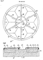
- Fig. 1 eine periphere Anordnung von Spiegelsegmenten auf einem Rundtisch einer erfindungsgemäßen Vermessungsvorrichtung;
- Fig. 2 eine schematische Aufsicht auf die Vorrichtung gemäß Fig. 1;
- Fig. 3 eine seitliche Schnittansicht der Vorrichtung gemäß Fig. 1 und 2;
- Fig. 4 eine schematisierte Draufsicht auf einen Teil einer Meßeinrichtung;
- Fig. 5 eine schematisierte Seitenansicht entsprechend Fig. 4;
- Fig. 6 eine Rückansicht der Meßeinrichtung gemäß Fig. 4 und 5;
- Fig. 7 eine schematische Aufsicht auf eine erfindungsgemäße Poliervorrichtung und
- Fig. 8 eine seitliche Schnittansicht der Poliervorrichtung gemäß Fig. 7.
- 1 shows a peripheral arrangement of mirror segments on a rotary table of a measuring device according to the invention;
- FIG. 2 shows a schematic plan view of the device according to FIG. 1;
- 3 shows a sectional side view of the device according to FIGS. 1 and 2;
- 4 shows a schematic plan view of part of a measuring device;
- Fig. 5 is a schematic side view corresponding to Fig. 4;
- 6 shows a rear view of the measuring device according to FIGS. 4 and 5;
- Fig. 7 is a schematic plan view of a polishing device according to the invention and
- 8 is a sectional side view of the polishing apparatus shown in FIG. 7.
Die in Fig. 1 und 2 gezeigte erfindungsgemäße Vorrichtung umfaßt einen großen luftgelagerten Rundtisch, auf dem die zu vermessenden Werkstücke, im Ausführungsbeispiel mehrere Spiegelsegmente 20, zusammen mit ihren Tragelementen peripher aufgebaut werden. Die als Vermessungsmaschine 10 für diese Spiegelsegmente 20 dienende Vorrichtung umfaßt einen Grundrahmen 12, in dem eine Spindel 14 (Fig. 3) gelagert ist, die die Spiegelsegmente trägt. Die Spindel 14 ist gegenüber dem Grundrahmen durch einen Motorantrieb um eine senkrecht zur Zeichnungsebene stehende, zentrale Rotationsachse 15 drehbar; diese Drehung erfolgt relativ langsam, beispielsweise mit einer Umdrehung pro Minute. Außerdem ist mit der Spindel ein (nicht dargestellter) Encoder zur Bestimmung der Winkelstellung der Spindel 14 gegenüber dem Grundrahmen 12 verbunden. Der Encoder kann als Glasmaßstab ausgeführt werden und gestattet eine Genauigkeit der Winkelstellungsbestimmung im Bereich von 10 bis 20 Bogensekunden. Die mittels des Encoders ermittelten Daten zur Stellung der Spindel werden in einen Computer eingegeben.The device according to the invention shown in FIGS. 1 and 2 comprises a large air-bearing rotary table on which the workpieces to be measured, in the exemplary embodiment a plurality of
Die Vermessungsmaschine 10 wird vorzugsweise in einem vibrationsentkoppelten, klimatisierten Reinraum aufgestellt.The measuring
Oberhalb der Oberflächen 34 der Spiegelsegmente 20 sind Meßeinrichtungen 16 vorgesehen, die fest mit dem Grundrahmen 12 verbunden sind und bei der Verdrehung der Spindel 14 nicht mitverdreht werden.Measuring
Wie Fig. 2 zeigt, sind drei Meßeinrichtungen 16 vorgesehen. Der Radialwinkel zwischen zwei Meßeinrichtungen beträgt jeweils 120°.As shown in FIG. 2, three measuring
Die Meßeinrichtungen 16 sind mit Heterodyn-Interferometern ausgestattet. Diese entsprechen im Ausführungsbeispiel den von der Firma Zygo erhältlichen Heterodyn-Interferometern vom Typ Axiom 2/20, sind aber hinsichtlich des Strahlenganges abgewandelt.The measuring
Ein Laserkopf und Empfänger 22 jedes Interferometers ist nahe der Rotationsachse der Spindel 14 so angeordnet, daß der Strahlengang vom Laser radial auswärts gerichtet ist, wie der Pfeil R in Fig. 3 bis 5 angibt. Der Strahlengang zurück zum Empfänger ist radial einwärts gerichtet.A laser head and
Entlang dem Strahlengang des Laserkopfs/Empfängers 22 verläuft eine Führungsbahn 24 radial auswärts (Fig. 3), wobei das rotationsachsennahe Ende der Führungsbahn als Halterung für den Laserkopf/Empfänger 22 dienen kann.A
Ein Meßkopf 28 des Heterodyn-Interferometers ist entlang der Führungsbahn 24 in radialer Richtung verschiebbar, so daß er über die gesame Breite des Spiegelsegments 20 in radialer Richtung verfahren werden kann. Die Bewegung des Meßkopfes 28 erfolgt durch im Stand der Technik bekannte Vorrichtungen.A measuring
Die Gradlinigkeit der Führungsbahn 24 in horizontaler wie vertikaler Hinsicht ist relativ unkritisch; Gradinigkeiten von 10 µm reichen aus.The straightness of the
Entlang der Führungsbahn 24 erstreckt sich ein als Encoder für die Radialstellung des Meßkopfes dienender Glasmaßstab oder dergleichen, der in den Fig. nicht gezeigt ist.A glass scale or the like serving as an encoder for the radial position of the measuring head, which is not shown in the figures, extends along the
Neben der Führungsbahn 24 erstreckt sich, wie Fig. 4 zeigt, parallel ein Referenzelement 26, das beispielsweise durch ein poliertes Zerodurlineal gebildet wird. Das Referenzelement 26 ist im Abstand einiger Millimeter über der Oberfläche 34 des Spiegelsegmentes 20 aufgehängt, und wird im Ausführungsbeispiel von den Abstützungen für die Führungsbahn 24 getragen, die sich einerseits nahe der Rotationsachse, andererseits am Außenumfang der Vermessungsmaschine 10 vom Grundrahmen 12 erheben.4, a
Der Meßkopf 28 ermöglicht eine interferometrische Vermessung sowohl hinsichtlich des Referenzelementes 26, als auch der Oberfläche 34, wie in Fig. 4 bis 6 einerseits durch eine gepunktete, andererseits durch eine durchgezogene Linie angedeutet ist.The measuring
Die vom Heterodyn-Interferometer ermittelten Daten werden ebenfalls in den genannten Computer eingegeben.The data determined by the heterodyne interferometer are also input into the computer mentioned.
Der Vermessungsvorgang beginnt mit dem Einmessen der Referenzelemente mittels der zugeordneten Heterodyn-Interferometer. Dazu wird der Meßkopf 28 auf der Führungsbahn 24 entlang dem zugeordneten Referenzelement 26 verfahren, dessen Kontur zunächst nur näherungsweise bekannt ist. Die Vermessung erfolgt bezüglich eines Geradlinigkeitsnormals bekannter Geometrie, beispielsweise einer Quecksilberoberfläche, mit einer Genauigkeit besser als 10 nm. So wird eine Bezugskontur 26′ am Referenzelement ermittelt, die datenmäegebenen, im Computer bereits gespeicherten Sollwerte können die Abweichungen von der Sollgeometrie bestimmt werden.The measurement process begins with the calibration of the reference elements using the assigned heterodyne interferometer. For this purpose, the measuring
Falls erforderlich, können Axialschlag der Spindel, Vibrationen und dergleichen überwacht und entsprechende Meßdaten dem Computer zur Kompensation übermittelt werden. Hierzu können beispielsweise weitere unabhängige Interferometer eingesetzt werden.If necessary, axial runout of the spindle, vibrations and the like can be monitored and corresponding measurement data can be transmitted to the computer for compensation. For example, other independent interferometers can be used for this purpose.
Ein (nicht gezeigter) Wellenlängenkompensator mit einer Auflösung von beispielsweise 5 x 10⁻⁹ stellt luftdruckabhängige Wellenlängenänderungen fest und ermöglicht eine entsprechende Kompensation der Meßdaten.A (not shown) wavelength compensator with a resolution of, for example, 5 x 10⁻⁹ detects changes in wavelength dependent on air pressure and enables a corresponding compensation of the measurement data.
Bei der Messung erfolgt die genannte langsame Drehbewegung der Spindel 14, so daß zusammen mit der radialen linearen Bewegung des Meßkopfes 28 die zu vermessenden Oberflächenbereiche spiralförmig radial einwärts oder auswärts von den Meßeinrichtungen überstrichen werden. Wegen der genannten geometrischen Bedingungen sind die Toleranzen bezüglich der Oberflächen-Hauptebene nicht sehr kritisch. Dies gilt natürlich nicht für die Toleranzen in zur Hauptebene senkrechter Richtung, d. h. Axialrichtung der Spindel 14.During the measurement, the mentioned slow rotational movement of the
Während sich die zu vermessende Oberfläche unter der Meßeinrichtung 16 durchbewegt, wird, wie schon gesagt, die Ist-Kontur gemessen und im Computer gespeichert.As already said, while the surface to be measured is moving under the measuring
Damit die interferometrisch abgetasteten Werkstück- und Referenzelement-Oberflächen keine Fehlmessungen ergeben, müssen diese staubfrei bleiben. Zur Entfernung von Staub u.dgl. kann eine zwischen den Meßeinrichtungen angeordnete eine Säuberungsvorrichtung, beispielsweise eine Absaugvorrichtung (nicht gezeigt) eingesetzt werden.To ensure that the workpiece and reference element surfaces scanned interferometrically do not result in incorrect measurements, they must remain dust-free. For removing dust and the like. a cleaning device, for example a suction device (not shown) arranged between the measuring devices, can be used.
Fig. 7 und 8 zeigen eine erfindungsgemäße Poliervorrichtung, mit der das erfindungsgemäße Bearbeitungsverfahren durchgeführt werden kann.7 and 8 show a polishing device according to the invention with which the machining method according to the invention can be carried out.
In ihrem grundsätzlichen Aufbau entspricht die Poliervorrichtung 10′ der bereits anhand Fig. 1 bis 6 beschriebenen Vermessungsvorrichtung. Daher entsprechen die in Fig. 7 und 8 gezeigten Teile den Teilen in Fig. 1 bis 6, die gleiche Bezugszeichen tragen.In its basic structure, the polishing device 10 'corresponds to the measuring device already described with reference to FIGS. 1 to 6. Therefore, the parts shown in Figs. 7 and 8 correspond to the parts in Figs. 1 to 6 which have the same reference numerals.
Gegenüber der Vermessungsvorrichtung (Fig. 1 bis 6) kommen bei der Poliervorrichtung nur Bearbeitungseinheiten 18 hinzu.Compared to the measuring device (FIGS. 1 to 6), only processing
Die Bearbeitungseinheiten 18 sind ebenfalls fest mit dem Grundrahmen 12 verbunden und werden bei der Verdrehung der Spindel 14 nicht mitverdreht. Im Ausführungsbeispiel sind drei Bearbeitungseinheiten 18 um jeweils 120° zueinander versetzt so gegenüber den Meßeinrichtungen 16 angeordnet, daß jeweils zwischen zwei Meßeinrichtungen 16 eine Bearbeitungseinheit 18 liegt und der Winkel zwischen benachbarten Meßeinrichtungen 16 und Bearbeitungseinheiten 18 gerade 60° beträgt.The
Die Bearbeitungseinheiten 18 weisen, ähnlich wie die Meßeinrichtungen 16, eine Führungsbahn 32 auf, die oberhalb der Oberfläche 34 des Spiegelsegments 20 verläuft und am nichtverdrehten Teil der Poliermaschine 10′ abgestützt ist.The
Entlang der Führungsbahn 32 ist ein Polierkopf 30 über die gesamte Radialerstreckung des Spiegelsegments 20 verfahrbar. Größe und Formgebung des Polierstiftes des Polierkopfes 30 werden auf die Geometrie der zu bearbeitenden Oberfläche abgestimmt.Along the
Antrieb und Verstellung des Polierkopfes 30 erfolgen durch im Stand der Technik bekannte Vorrichtungen; ein sich entlang der Führungsbahn 32 erstreckender Encoder (nicht gezeigt), der ebenfalls durch einen Glasmaßstab gebildet werden kann, ermöglicht die Feststellung der jeweiligen Radialposition des Polierkopfes 30. Im Betrieb wird der Polierkopf 30 auf der Grundlage der im Computer gespeicherten Daten stets im gleichen Abstand zur Rotationsachse 15 (Rundtischmitte) gehalten wie der zugeordnete Interferometermeßkopf 28, d. h. der Meßkopf der in Bearbeitungsrichtung A (Fig. 7) vorausgehenden Meßeinrichtung 16. Die Polierstifte der Polierköpfe 30 werden computergesteuert auf die Oberfläche aufgesetzt bzw. von dieser abgehoben. Der Bearbeitungsdruck der Polierstifte auf die Oberfläche wird so eingestellt, daß der Materialabtrag zwischen zwei Interferometerplätzen höchstens gleich der zulässigen Konturtoleranz (z. B. 25 nm) ist.The polishing
Der Bearbeitungsvorgang beginnt, wie der schon beschriebene Vermessungsvorgang, mit dem Einmessen der Referenzelemente 26. Es folgt die schon beschriebene Vermessung der Oberflächenkontur-Istwerte und die rechnerische Bestimmung der Abweichungen von der Sollgeometrie der Oberfläche.The machining process begins, like the measurement process already described, with the measurement of the
Bei der Drehbewegung der Spindel 14 werden Bearbeitungsbereiche gebildet, die sich entsprechend den schon be schriebenen Vermessungsbereichen spiralförmig radial einwärts oder auswärts erstrecken. Der Abstand der Spiralbahnen entspricht der Wegstrecke, auf der sich die Pfeilhöhe der Spiegeloberfläche in radialer Richtung bezüglich des Referenzelementes um eine Toleranzeinheit ändert, beispielsweise um 25 nm. Bei langbrennweitigen Parabolsegmenten macht dies typischerweise einige Zehntel Millimeter aus, bei günstiger Ausbildung der Referenzelemente sogar nur einige Millimeter. Diese Bahnabstände werden bei der Wahl der Polierstifte hinsichtlich Größe und Formgebung zugrundegelegt.During the rotational movement of the
Während sich die Oberfläche unter der Meßeinrichtung 16 durchbewegt, wird ihre Ist-Kontur gemessen und datenmäßig im Computer gespeichert. Mittels dieser gespeicherten Ist-Konturdaten erfolgt die Steuerung der in Bearbeitungsrichtung A folgenden Bearbeitungseinheit, also des Polierkopfes 30. Die Abtragsrate wird dabei so eingestellt, daß der Abtrag zwischen zwei in Bearbeitungsrichtung A aufeinanderfolgenden Meßeinheiten kleiner ist als die Toleranzeinheit (z. B. 25 nm). Das bedeutet, daß zwischen zwei Meßvorgängen nie so viel Material abgetragen werden kann, daß die Konturtoleranz überschritten wird.While the surface is moving under the measuring
Die der genannten Bearbeitungsstation in Bearbeitungsrichtung A folgende Meßeinrichtung 16 stellt fest, ob der vorausgegangene Bearbeitungsschritt die Oberflächen-Istkontur bereits in den Toleranzbereich der Oberflächen-Sollkontur gebracht hat. Wenn dies der Fall ist, wird die nachfolgende Bearbeitungsstation in diesem Bearbeitungsbereich nicht betätigt, so daß kein weiterer Abtrag erfolgt.The measuring
Die Meß- und Bearbeitungsvorgänge werden solange wiederholt, bis sämtliche Spiegelsegmente innerhalb der Toleranz die Oberflächen-Sollkontur erreicht haben.The measuring and machining processes are repeated until all mirror segments have reached the target surface contour within the tolerance.
Die bereits genannte Absaugvorrichtung dient bei der Bearbeitung vorteilhaft zur Entfernung von Abtragungsrückständen.The above-mentioned suction device advantageously serves for the removal of removal residues during processing.
Die Trennung des Meßvorganges zum zugeordneten Bearbeitungsvorgang (d. h. beim gleichen Oberflächenbereich) in zeitlicher Hinsicht ermöglicht es, daß beim Bearbeiten entstehende lokale Erwärmungen sich vor der nächsten Messung wieder abbauen und Luftwirbel abklingen.The separation of the measuring process from the assigned machining process (i.e. with the same surface area) in terms of time enables local heating that occurs during machining to be reduced again before the next measurement and air vortices to subside.
Wenn eine Unterbrechung der Bearbeitung an Fugen und Aussparungen zwischen einzelnen Werkstückteilen, beispielsweise Spiegelsegmenten, unerwünscht ist, können Füllkörper eingesetzt und mitpoliert werden.If an interruption in the machining of joints and recesses between individual workpiece parts, for example mirror segments, is undesirable, fillers can be used and also polished.
Es versteht sich, daß der gesamte Bearbeitungsvorgang beendet wird, sobald die Meßeinheiten das Erreichen der Sollkontur für die gesamte Oberfläche feststellen.It goes without saying that the entire machining process is ended as soon as the measuring units determine that the target contour has been reached for the entire surface.
Claims (58)
dadurch gekennzeichnet, daß
characterized in that
dadurch gekennzeichnet, daß das Referenzelement und die zu bearbeitende Oberfläche relativ zueinander bewegt werden.2. The method according to claim 1,
characterized in that the reference element and the surface to be machined are moved relative to each other.
dadurch gekennzeichnet, daß das Referenzelement auf eine gedachte Radiallinie bezüglich einer senkrechten Rotaionsachse durch die Oberflächenhauptebene liegt, um welche Rotationsachse die Oberfläche gedreht wird, so daß der im wesentlichen radial verlaufende Vermessungsbereich einen Teil einer Spirallinie auf der Oberfläche bildet.3. The method according to claim 2,
characterized in that the reference element lies on an imaginary radial line with respect to a vertical axis of rotation through the main surface plane, about which axis of rotation the surface is rotated, so that the essentially radially extending measurement area forms part of a spiral line on the surface.
dadurch gekennzeichnet, daß jede von einem Vermessungsbereich gebildete Spiralbahn der Spirallinie einer Wegstrecke entspricht, auf der sich die Pfeilhöhe der Oberfläche in radialer Richtung bezüglich der Bezugskontur des Referenzelementes um die Konturtoleranz ändert.4. The method according to claim 3,
characterized in that each spiral path formed by a measurement area of the spiral line corresponds to a distance on which the arrow height of the surface changes in the radial direction with respect to the reference contour of the reference element by the contour tolerance.
dadurch gekennzeichnet, daß der Meßkopf des Interferometers in inkrementellen Schritten entlang der zugeordneten Radiallinie über den Vermessungsbereich bewegt wird.5. The method according to claim 3 or 4,
characterized in that the measuring head of the interferometer is moved in incremental steps along the assigned radial line over the measurement area.
dadurch gekennzeichnet, daß mehrere Referenzelemente beabstandet aufeinanderfolgend verwendet werden.6. The method according to any one of claims 1 to 5,
characterized in that several reference elements are used successively spaced apart.
dadurch gekennzeichnet, daß die Bestimmung der Ist- und Sollwerte durch Laser-Interferometer erfolgt und gegebenenfalls der Einfluß der Wellenlängen-Luftdruckabhängigkeit des Laserlichts interferometrisch in Echtzeit zur Korrektur erfaßt wird.7. The method according to any one of claims 1 to 6,
characterized in that the actual and target values are determined by laser interferometers and, if necessary, the influence of the wavelength-air pressure dependency of the laser light is recorded interferometrically in real time for correction.
dadurch gekennzeichnet, daß scannende Heterodyn-Interferometer zusammen mit linearen Referenzelementen verwendet werden.8. The method according to any one of claims 1 to 7,
characterized in that scanning heterodyne interferometers are used together with linear reference elements.
dadurch gekennzeichnet, daß die Oberflächen-Hauptebene im wesentlichen horizontal bezüglich der Gravitationsrichtung ausgerichtet wird und das Referenzelement im geringen Abstand von der Oberfläche oberhalb dieser aufgehängt oder abgestützt wird.9. The method according to any one of claims 1 to 8,
characterized in that the main surface plane is aligned substantially horizontally with respect to the direction of gravity and the reference element is suspended or supported at a short distance from the surface above it.
dadurch gekennzeichnet, daß die Oberfläche vorbereitend auf eine Konturrichtigkeit im Bereich einiger 10⁻⁶m vorpoliert wird.10. The method according to any one of claims 1 to 9,
characterized in that the surface is prepolished in preparation for a contour accuracy in the range of a few 10⁻⁶m.
dadurch gekennzeichnet, daß die interferometrischen Erfassungsvorgänge, die Berechnungen sowie die Steuer- und Regelvorgänge bei der Vermessung mittels eines Computers automatisiert vorgenommen werden.11. The method according to any one of claims 1 to 10,
characterized in that the interferometric acquisition processes, the calculations and the control and regulating processes during the measurement are carried out automatically by means of a computer.
dadurch gekennzeichnet, daß mittels des Computers die geometrischen Soll-Daten der Oberfläche berechnet bzw. gespeichert werden.12. The method according to claim 11,
characterized in that the geometric target data of the surface are calculated or stored by means of the computer.
dadurch gekennzeichnet, daß der Materialabtrag durch wenigstens ein antreibbares gesteuertes Werkzeug einer Bearbeitungseinheit, insbesondere einen oder mehrere Polierstifte erfolgt.14. The method according to claim 13,
characterized in that the material is removed by at least one drivable controlled tool of a processing unit, in particular one or more polishing pins.
dadurch gekennzeichnet, daß das Referenzelement und eine Bearbeitungseinheit in festem Abstand zueinander angeordnet werden und die zu bearbeitende Oberfläche relativ dazu bewegt wird, so daß der Bearbeitungsbereich nacheinander in entsprechende Stellungen gegenüber dem Referenzelement und der Bearbeitungseinheit gebracht wird.15. The method according to claim 13 or 14,
characterized in that the reference element and a machining unit are arranged at a fixed distance from one another and the surface to be machined is moved relative thereto, so that the machining region is successively brought into corresponding positions with respect to the reference element and the machining unit.
dadurch gekennzeichnet, daß das Referenzelement und die Bearbeitungseinheit auf gedachten Radiallinien bezüglich einer senkrechten Rotationsachse durch die Oberflächenhauptebene liegen, um welche Rotationsachse die Oberfläche gedreht wird, so daß der im wesentlichen radial verlaufende Bearbeitungsbereich einen Teil einer Spirallinie auf der Oberfläche bildet.16. The method according to claim 15,
characterized in that the reference element and the processing unit lie on imaginary radial lines with respect to a vertical axis of rotation through the main surface plane, about which axis of rotation the surface is rotated, so that the essentially radially extending processing area forms part of a spiral line on the surface.
dadurch gekennzeichnet, daß jede der von den Bearbeitungsbereichen gebildeten Spiralbahnen der Spirallinie einer Wegstrecke entspricht, auf der sich die Pfeilhöhe der Oberfläche in radialer Richtung bezüglich der Bezugskontur des Referenzelementes um die Konturtoleranz ändert.17. The method according to claim 16,
characterized in that each of the spiral paths formed by the machining areas of the spiral line corresponds to a distance on which the arrow height of the surface changes in the radial direction with respect to the reference contour of the reference element by the contour tolerance.
dadurch gekennzeichnet, daß wenigstens ein Bearbeitungswerkzeug der Bearbeitungseinheit und der Meßkopf des Interferometers in einander zugeordneten inkrementellen Schritten entlang den jeweiligen Radiallinien bewegt werden.18. The method according to claim 16 or 17,
characterized in that at least one machining tool of the machining unit and the measuring head of the interferometer are moved along the respective radial lines in incremental steps assigned to one another.
dadurch gekennzeichnet, daß mehrere Referenzelemente und Bearbeitungseinheiten alternierend aufeinanderfolgend verwendet werden.19. The method according to any one of claims 13 to 18,
characterized in that several reference elements and processing units are used alternately in succession.
dadurch gekennzeichnet, daß die Bestimmung der Ist- und Sollwerte durch Laser-Interferometer erfolgt und gegebenenfalls der Einfluß der Wellenlängen-Luftdruckabhängigkeit des Laserlichts interferometrisch in Echtzeit zur Korrektur erfaßt wird.20. The method according to any one of claims 13 to 19,
characterized in that the actual and target values are determined by laser interferometers and, if necessary, the influence of the wavelength-air pressure dependency of the laser light is recorded interferometrically in real time for correction.
dadurch gekennzeichnet, daß scannende Heterodyn-Interferometer zusammen mit linearen Referenzelementen verwendet werden.21. The method according to any one of claims 13 to 20,
characterized in that scanning heterodyne interferometers are used together with linear reference elements.
dadurch gekennzeichnet, daß die Oberflächen-Hauptebene im wesentlichen horizontal bezüglich der Gravitationsrichtung ausgerichtet wird und das Referenzelement im geringen Abstand von der Oberfläche oberhalb dieser aufgehängt oder abgestützt wird.22. The method according to any one of claims 13 to 21,
characterized in that the main surface plane is aligned substantially horizontally with respect to the direction of gravity and the reference element is suspended or supported at a short distance from the surface above it.
dadurch gekennzeichnet, daß die Oberfläche vorbereitend auf eine Konturrichtigkeit im Bereich einiger 10⁻⁶m vorpoliert wird.23. The method according to any one of claims 13 to 22,
characterized in that the surface is preparatory is polished to a contour accuracy in the range of a few 10⁻⁶m.
dadurch gekennzeichnet, daß mittels des Computers die geometrischen Soll-Daten der Oberfläche berechnet bzw. gespeichert werden.25. The method according to claim 24,
characterized in that the geometric target data of the surface are calculated or stored by means of the computer.
dadurch gekennzeichnet, daß
characterized in that
dadurch gekennzeichnet, daß eine Tragstruktur (12, 14) zur Aufnahme des Werkstücks mit bezüglich der Gravitationsrichtung im wesentlichen waagerecht liegender Oberflächen-Hauptebene vorgesehen ist.27. The apparatus according to claim 26,
characterized in that a supporting structure (12, 14) is provided for receiving the workpiece with the main surface plane lying substantially horizontal with respect to the direction of gravity.
dadurch gekennzeichnet, daß die Tragstruktur von einem Rundtisch mit einer Spindel (14) gebildet wird, die um eine vertikale Rotationsachse drehbar ist.28. The device according to claim 27,
characterized in that the support structure is formed by a rotary table with a spindle (14) which is rotatable about a vertical axis of rotation.
dadurch gekennzeichnet, daß die Tragstruktur bzw. der Rundtisch eine luftgelagerte Spindel (14) aufweist, der ein Encoder zur Ermittlung der Winkelstellung der Spindel bezüglich der nicht verdrehten Tragstruktur zugeordnet ist, wobei die Spindel vorzugsweise einen Axialschlag von weniger als 0,1 Bogensekunden aufweist.29. The device according to claim 27 or 28,
characterized in that the support structure or the rotary table has an air-bearing spindle (14) to which an encoder is assigned for determining the angular position of the spindle with respect to the non-rotated support structure, the spindle preferably having an axial stroke of less than 0.1 arc seconds.
dadurch gekennzeichnet, daß die Tragstruktur einen im Betrieb nicht mitverdrehten Grundrahmen (12) umfaßt.30. Device according to one of claims 27 to 29,
characterized in that the supporting structure comprises a base frame (12) which is not rotated during operation.
dadurch gekennzeichnet, daß die Meßeinrichtungen (16) ortsfest oberhalb der Oberfläche (34) des Werkstücks (20) angeordnet, insbesondere am Grundrahmen (12) aufgehängt bzw. abgestützt sind und bei der Verdrehung des Werkstücks nicht mitverdreht werden.31. Device according to one of claims 26 to 30,
characterized in that the measuring devices (16) are arranged in a stationary manner above the surface (34) of the workpiece (20), in particular are suspended or supported on the base frame (12) and are not rotated when the workpiece is rotated.
dadurch gekennzeichnet, daß die Meßeinrichtung eine horizontal, insbesondere von der Rotationsachse radial bis über die äußere Begrenzung der zu bearbeitenden Oberfläche (34) hinaus verlaufende Führungsbahn (24) aufweist, entlang derer der Interferometer-Meßkopf (28) verfahrbar ist.32. Device according to one of claims 26 to 31,
characterized in that the measuring device has a guide track (24) which extends horizontally, in particular radially from the axis of rotation to beyond the outer boundary of the surface (34) to be machined, along which the interferometer measuring head (28) can be moved.
dadurch gekennzeichnet, daß jeweils mehrere gleiche Meßeinrichtungen (16) vorgesehen sind, insbesondere drei um 120° um die Rotationsachse des Rundtisches winkelbeabstandete Meßeinrichtungen (16) vorgesehen sind.33. Device according to one of claims 26 to 32,
characterized in that several identical measuring devices (16) are provided, in particular three measuring devices (16) spaced at an angle of 120 ° about the axis of rotation of the rotary table.
dadurch gekennzeichnet, daß die Meßeinrichtungen (16) mit Encodern wie beispielsweise Glasmaßstäben oder dergleichen zur Erfassung der Stellung, insbesondere der Radialstellung des jeweiligen Meßkopfes (28) versehen sind, wobei sich die Encoder insbesondere entlang den Führungsbahnen (24) erstrecken.34. Device according to one of claims 26 to 33,
characterized in that the measuring devices (16) are provided with encoders such as glass scales or the like for detecting the position, in particular the radial position, of the respective measuring head (28), the encoders in particular extending along the guideways (24).
dadurch gekennzeichnet, daß die Interferometer-Meßeinrichtungen (16) als scannende Heterodyn-Interferometer ausgebildet sind, wobei insbesondere die Laserköpfe und Empfänger (22) nahe der Rotationsachse des Rundtisches bzw. der Spindel (14) angeordnet sind.35. Device according to one of claims 26 to 34,
characterized in that the interferometer measuring devices (16) are designed as scanning heterodyne interferometers, in particular the laser heads and receivers (22) being arranged near the axis of rotation of the rotary table or the spindle (14).
dadurch gekennzeichnet, daß ein interferometrischer Wellenlängen-Kompensator vorgesehen ist, der luftdruck abhängige Wellenlängenänderungen zur Kompensation erfaßt.36. Device according to one of claims 26 to 35,
characterized in that an interferometric wavelength compensator is provided, the air pressure dependent wavelength changes detected for compensation.
dadurch gekennzeichnet, daß die Referenzelemente (26) im wesentlichen linear ausgebildet sind und sich insbesondere parallel zur zugeordneten Führungsbahn (24) erstrecken, und insbesondere aus langgestreckten mechanisch formstabilen Körpern, beispielsweise einem polierten Zerodurlineal, bestehen.37. Device according to one of claims 26 to 36,
characterized in that the reference elements (26) are essentially linear and in particular extend parallel to the associated guideway (24), and in particular consist of elongated mechanically dimensionally stable bodies, for example a polished Zerodur ruler.
dadurch gekennzeichnet, daß die Referenzelemente (26) im Abstand einiger Millimeter über der zu bearbeitenden Oberfläche (34) aufgehängt bzw. abgestützt sind.38. Device according to one of claims 26 to 37,
characterized in that the reference elements (26) are suspended or supported at a distance of a few millimeters above the surface (34) to be processed.
dadurch gekennzeichnet, daß wenigstens ein weiteres unabhängiges Interferometer zur Erfassung des Axialschlags der Spindel, zur Erfassung von Vibrationen der Vorrichtung und dergleichen vorgesehen ist.39. Device according to one of claims 26 to 38,
characterized in that at least one further independent interferometer is provided for detecting the axial stroke of the spindle, for detecting vibrations of the device and the like.
dadurch gekennzeichnet, daß ein Computer zur Speicherung der Sollkontur-Daten, der Istkontur-Meßdaten und zur Berechnung der Differenz zwischen beiden vorgesehen ist.40. Device according to one of claims 26 to 39,
characterized in that a computer is provided for storing the target contour data, the actual contour measurement data and for calculating the difference between the two.
dadurch gekennzeichnet, daß
characterized in that
dadurch gekennzeichnet, daß eine Tragstruktur (12, 14) zur Aufnahme des Werkstücks mit bezüglich der Gravita tionsrichtung im wesentlichen waagerecht liegender Oberflächen-Hauptebene vorgesehen ist.42. Device according to claim 41,
characterized in that a support structure (12, 14) for receiving the workpiece with respect to the gravita tion direction is essentially horizontally lying surface main plane.
dadurch gekennzeichnet, daß die Tragstruktur von einem Rundtisch mit einer Spindel (14) gebildet wird, die um eine vertikale Rotationsachse drehbar ist.43. Device according to claim 42,
characterized in that the support structure is formed by a rotary table with a spindle (14) which is rotatable about a vertical axis of rotation.
dadurch gekennzeichnet, daß die Tragstruktur bzw. der Rundtisch eine luftgelagerte Spindel (14) aufweist, der ein Encoder zur Ermittlung der Winkelstellung der Spindel bezüglich der nicht verdrehten Tragstruktur zugeordnet ist, wobei die Spindel vorzugsweise einen Axialschlag von weniger als 0,1 Bogensekunden aufweist.44. Device according to claim 42 or 43,
characterized in that the support structure or the rotary table has an air-bearing spindle (14) to which an encoder is assigned for determining the angular position of the spindle with respect to the non-rotated support structure, the spindle preferably having an axial stroke of less than 0.1 arc seconds.
dadurch gekennzeichnet, daß die Tragstruktur einen im Betrieb nicht mitverdrehten Grundrahmen (12) umfaßt.45. Device according to one of claims 42 to 44,
characterized in that the supporting structure comprises a base frame (12) which is not rotated during operation.
dadurch gekennzeichnet, daß die Meßeinrichtungen (16) und die Bearbeitungseinheiten (18) ortsfest oberhalb der Oberfläche (34) des Werkstücks (20) angeordnet, insbesondere am Grundrahmen (12) aufgehängt bzw. abgestützt sind und bei der Verdrehung des Werkstücks nicht mitverdreht werden.46. Device according to one of claims 41 to 45,
characterized in that the measuring devices (16) and the processing units (18) are arranged in a stationary manner above the surface (34) of the workpiece (20), in particular are suspended or supported on the base frame (12) and are not rotated when the workpiece is rotated.
dadurch gekennzeichnet, daß die Meßeinrichtung und die Bearbeitungseinheit horizontal, insbesondere von der Rotationsachse radial bis über die äußere Begrenzung der zu bearbeitenden Oberfläche (34) hinaus verlaufende Führungsbahnen (24 bzw. 32) aufweisen, entlang derer einesfalls der Interferometer-Meßkopf (28), andernfalls das Bearbeitungswerkzeug (30) verfahrbar ist.47. Device according to one of claims 41 to 46,
characterized in that the measuring device and the processing unit horizontally, in particular radially from the axis of rotation to beyond the outer boundary of the surface (34) to be machined have guideways (24 or 32), along which the interferometer measuring head (28), otherwise the machining tool (30) can be moved.
dadurch gekennzeichnet, daß jeweils mehrere gleiche, alternierend angeordnete Meßeinrichtungen (16) und Bearbeitungseinheiten (18) vorgesehen sind, insbesondere drei um 120° um die Rotationsachse des Rundtisches winkelbeabstandete Meßeinrichtungen (16) und drei um 120° um die Rotationsachse winkelbeabstandete Bearbeitungseinheiten (18) so vorgesehen sind, daß einander benachbarte Meßeinrichtungen und Bearbeitungseinheiten unter einem Winkel von 60° zueinander liegen.48. Device according to one of claims 41 to 47,
characterized in that several identical, alternately arranged measuring devices (16) and processing units (18) are provided, in particular three measuring devices (16) spaced at an angle of 120 ° about the axis of rotation of the rotary table and three processing units (18) at an angle of 120 ° around the axis of rotation are provided so that adjacent measuring devices and processing units are at an angle of 60 ° to each other.
dadurch gekennzeichnet, daß die Meßeinrichtungen (16) und die Bearbeitungseinheiten (18) mit Encodern wie beispielsweise Glasmaßstäben oder dergleichen zur Erfassung der Stellung, insbesondere der Radialstellung des jeweiligen Meßkopfes (28) bzw. Werkzeugs (30) versehen sind, wobei sich die Encoder insbesondere entlang den Führungsbahnen (24 bzw. 32) erstrecken.49. Device according to one of claims 41 to 48,
characterized in that the measuring devices (16) and the processing units (18) are provided with encoders such as, for example, glass scales or the like for detecting the position, in particular the radial position of the respective measuring head (28) or tool (30), the encoders in particular extend along the guideways (24 or 32).
dadurch gekennzeichnet, daß die Interferometer-Meßeinrichtungen (16) als scannende Heterodyn-Interferometer ausgebildet sind, wobei insbesondere die Laserköpfe und Empfänger (22) nahe der Rotationsachse des Rundtisches bzw. der Spindel (14) angeordnet sind.50. Device according to one of claims 41 to 49,
characterized in that the interferometer measuring devices (16) are designed as scanning heterodyne interferometers, in particular the laser heads and receivers (22) being arranged near the axis of rotation of the rotary table or the spindle (14).
dadurch gekennzeichnet, daß ein interferometrischer Wellenlängen-Kompensator vorgesehen ist, der luftdruckabhängige Wellenlängenänderungen zur Kompensation erfaßt.51. Device according to one of claims 41 to 50,
characterized in that an interferometric wavelength compensator is provided which detects changes in wavelength dependent on air pressure for compensation.
dadurch gekennzeichnet, daß die Referenzelemente (26) im wesentlichen linear ausgebildet sind und sich insbesondere parallel zur zugeordneten Führungsbahn (24) erstrecken, und insbesondere aus langgestreckten mechanisch formstabilen Körpern, beispielsweise einem polierten Zerodurlineal, bestehen.52. Device according to one of claims 41 to 51,
characterized in that the reference elements (26) are essentially linear and in particular extend parallel to the associated guideway (24), and in particular consist of elongated mechanically dimensionally stable bodies, for example a polished Zerodur ruler.
dadurch gekennzeichnet, daß die Referenzelemente (26) im Abstand einiger Millimeter über der zu bearbeitenden Oberfläche (34) aufgehängt bzw. abgestützt sind.53. Device according to one of claims 41 to 52,
characterized in that the reference elements (26) are suspended or supported at a distance of a few millimeters above the surface (34) to be processed.
dadurch gekennzeichnet, daß elektronische Steuervorrichtungen zur Führung der Werkzeuge (30) auf der Radialposition des Meßkopfes (28) der bezüglich des Bearbeitungsablaufs der Oberfläche (34) vorausgehenden Meßeinrichtung (16) sowie zum Aufsetzen und Abheben des Bearbeitungswerkzeugs (30) auf die bzw. von der Oberfläche (34) vorgesehen sind.54. Device according to one of claims 41 to 53,
characterized in that electronic control devices for guiding the tools (30) on the radial position of the measuring head (28) of the measuring device (16) preceding the processing sequence of the surface (34) and for placing and lifting the processing tool (30) on or from the surface (34) are provided.
dadurch gekennzeichnet, daß Druckeinstellvorrichtungen für das Bearbeitungswerkzeug (30) vorgesehen sind, die den Bearbeitungsdruck des Werkzeugs so einzustellen gestatten, daß der Materialabtrag bei einem Bearbeitungsschritt höchstens gleich der zulässigen Konturtoleranz ist.55. Device according to one of claims 41 to 54,
characterized in that pressure adjusting devices for the machining tool (30) are provided, which adjust the machining pressure of the tool in this way allow the material removal in a machining step to be at most equal to the permissible contour tolerance.
dadurch gekennzeichnet, daß wenigstens ein weiteres unabhängiges Interferometer zur Erfassung des Axialschlags der Spindel, zur Erfassung von Vibrationen der Vorrichtung und dergleichen vorgesehen ist.56. Device according to one of claims 41 to 55,
characterized in that at least one further independent interferometer is provided for detecting the axial stroke of the spindle, for detecting vibrations of the device and the like.
dadurch gekennzeichnet, daß ein Computer zur Speicherung der Sollkontur-Daten, der Istkontur-Meßdaten, zur Berechnung der Differenz zwischen beiden und zur Steuerung der der jeweiligen Meßeinrichtung (16) zugeordneten Bearbeitungseinheit (18) vorgesehen ist.57. Device according to one of claims 41 to 56,
characterized in that a computer is provided for storing the target contour data, the actual contour measurement data, for calculating the difference between the two and for controlling the processing unit (18) associated with the respective measuring device (16).
dadurch gekennzeichnet, daß eine Säuberungs-, insbesondere Absaugvorrichtung zur Entfernung von Abtragungsrückständen von der Oberfläche vorgesehen ist.58. Device according to one of claims 41 to 57,
characterized in that a cleaning device, in particular a suction device, is provided for removing removal residues from the surface.
Applications Claiming Priority (2)
| Application Number | Priority Date | Filing Date | Title |
|---|---|---|---|
| DE3820225 | 1988-06-14 | ||
| DE3820225A DE3820225C1 (en) | 1988-06-14 | 1988-06-14 |
Publications (2)
| Publication Number | Publication Date |
|---|---|
| EP0346819A2 true EP0346819A2 (en) | 1989-12-20 |
| EP0346819A3 EP0346819A3 (en) | 1991-11-27 |
Family
ID=6356523
Family Applications (1)
| Application Number | Title | Priority Date | Filing Date |
|---|---|---|---|
| EP19890110657 Withdrawn EP0346819A3 (en) | 1988-06-14 | 1989-06-13 | Method and apparatus for the contactless measuring and optionally machining of surfaces |
Country Status (4)
| Country | Link |
|---|---|
| US (1) | US5067282A (en) |
| EP (1) | EP0346819A3 (en) |
| JP (1) | JPH02118407A (en) |
| DE (1) | DE3820225C1 (en) |
Families Citing this family (13)
| Publication number | Priority date | Publication date | Assignee | Title |
|---|---|---|---|---|
| US5430537A (en) * | 1993-09-03 | 1995-07-04 | Dynamics Research Corporation | Light beam distance encoder |
| US5649849A (en) * | 1995-03-24 | 1997-07-22 | Eastman Kodak Company | Method and apparatus for realtime monitoring and feedback control of the shape of a continuous planetary polishing surface |
| US6923711B2 (en) | 2000-10-17 | 2005-08-02 | Speedfam-Ipec Corporation | Multizone carrier with process monitoring system for chemical-mechanical planarization tool |
| NL1018943C2 (en) * | 2001-09-13 | 2003-03-14 | Tno | Method and device for polishing a workpiece surface. |
| NL1022293C2 (en) * | 2002-12-31 | 2004-07-15 | Tno | Device and method for manufacturing or processing optical elements and / or optical form elements, as well as such elements. |
| DE10315218B4 (en) * | 2003-04-01 | 2010-12-30 | Nagel Maschinen- Und Werkzeugfabrik Gmbh | Method and device for fine machining a surface of a workpiece |
| JP2006047148A (en) * | 2004-08-05 | 2006-02-16 | Mitsutoyo Corp | Shape measurement apparatus, shape measurement method, shape analysis apparatus, shape analysis program, and recording medium |
| JP4938231B2 (en) * | 2004-10-25 | 2012-05-23 | ルネサスエレクトロニクス株式会社 | Flatness measuring instrument |
| JP2009509124A (en) * | 2005-06-16 | 2009-03-05 | ザ リージェンツ オブ ザ ユニバーシティ オブ カリフォルニア | Devices for large parallel immune-based allergy testing and fluorescence evanescent field excitation |
| US20080011058A1 (en) * | 2006-03-20 | 2008-01-17 | The Regents Of The University Of California | Piezoresistive cantilever based nanoflow and viscosity sensor for microchannels |
| US8191403B2 (en) * | 2007-03-27 | 2012-06-05 | Richmond Chemical Corporation | Petroleum viscosity measurement and communication system and method |
| FR3023011B1 (en) * | 2014-06-27 | 2017-10-20 | Thales Sa | METHOD FOR MANUFACTURING A MIRROR |
| CN113933029A (en) * | 2021-10-15 | 2022-01-14 | 中国工程物理研究院激光聚变研究中心 | Off-axis aspheric element processing detection system and manufacturing method |
Citations (2)
| Publication number | Priority date | Publication date | Assignee | Title |
|---|---|---|---|---|
| FR2448417A1 (en) * | 1979-02-09 | 1980-09-05 | Inst Kosm I | Control system to finish large optical surface - uses sensors to measure momentary work and tool coordinates to control tool pressures and dwell times |
| GB2175687A (en) * | 1985-04-26 | 1986-12-03 | Suhl Feinmesszeugfab Veb | Interferometric-incremental device for testing flatness |
Family Cites Families (3)
| Publication number | Priority date | Publication date | Assignee | Title |
|---|---|---|---|---|
| US4365301A (en) * | 1980-09-12 | 1982-12-21 | The United States Of America As Represented By The United States Department Of Energy | Positional reference system for ultraprecision machining |
| DE3430499C2 (en) * | 1984-08-18 | 1986-08-14 | Fa. Carl Zeiss, 7920 Heidenheim | Method and device for lapping or polishing optical workpieces |
| US4794736A (en) * | 1985-12-27 | 1989-01-03 | Citizen Watch Co., Ltd. | Arrangement for mechanically and accurately processing a workpiece with a position detecting pattern or patterns |
-
1988
- 1988-06-14 DE DE3820225A patent/DE3820225C1/de not_active Expired
-
1989
- 1989-06-13 EP EP19890110657 patent/EP0346819A3/en not_active Withdrawn
- 1989-06-14 JP JP1153532A patent/JPH02118407A/en active Pending
-
1990
- 1990-12-07 US US07/625,640 patent/US5067282A/en not_active Expired - Fee Related
Patent Citations (2)
| Publication number | Priority date | Publication date | Assignee | Title |
|---|---|---|---|---|
| FR2448417A1 (en) * | 1979-02-09 | 1980-09-05 | Inst Kosm I | Control system to finish large optical surface - uses sensors to measure momentary work and tool coordinates to control tool pressures and dwell times |
| GB2175687A (en) * | 1985-04-26 | 1986-12-03 | Suhl Feinmesszeugfab Veb | Interferometric-incremental device for testing flatness |
Non-Patent Citations (1)
| Title |
|---|
| MESSTECHNIK, Band 81, Nr. 1, Januar 1973, Seiten 23-30, M}nchen, DE; K. ECKOLT et al.: "Verfahren zur Ebenheitsmessung" * |
Also Published As
| Publication number | Publication date |
|---|---|
| US5067282A (en) | 1991-11-26 |
| DE3820225C1 (en) | 1989-07-13 |
| JPH02118407A (en) | 1990-05-02 |
| EP0346819A3 (en) | 1991-11-27 |
Similar Documents
| Publication | Publication Date | Title |
|---|---|---|
| EP2399097B1 (en) | Method for zero-contact measurement of topography | |
| EP0346819A2 (en) | Method and apparatus for the contactless measuring and optionally machining of surfaces | |
| DE102005018787A1 (en) | Measurement of the shape of spherical and almost spherical optical surfaces | |
| DE10119662C2 (en) | Process for edge processing of optical lenses | |
| EP1663573B1 (en) | Grinding machine with a concentricity correction system | |
| DE2942388A1 (en) | SEMICONDUCTOR DEVICE POSITIONING DEVICE | |
| EP2190626A1 (en) | Method and device for machining workpieces | |
| EP1952927A1 (en) | Method for aligning a workpiece axis in a machine tool and machine tool | |
| EP1019669B1 (en) | Device for detecting the position of two bodies | |
| DE69912162T2 (en) | SANDERS | |
| EP3230008B1 (en) | Measuring steady rest for supporting and measuring central workpiece regions, grinding machine with such a measuring steady rest, and method for supporting and measuring central workpiece regions | |
| DE3836540C2 (en) | ||
| DE4305408A1 (en) | Method for measuring gears and arrangement for machining and measuring gears | |
| DE4412682C2 (en) | Device for measuring eccentrically rotating workpieces | |
| DE19524391A1 (en) | Polishing, drilling, cutting and welding ophthalmic lenses | |
| DE2938662C2 (en) | ||
| EP0289528B1 (en) | Deep grinding process and device | |
| DE10019962B4 (en) | Method and device for measuring surfaces, in particular for measuring spherical and aspherical surfaces | |
| DE4432317A1 (en) | Cutting angle measurement appts. for rotating cutting tool | |
| DE2011346A1 (en) | Device for measuring workpiece dimensions | |
| DE3113718C2 (en) | Profile grinding machine | |
| AT398246B (en) | DEVICE FOR CONTROLLING THE GEOMETRIC AND DYNAMIC ACCURACY OF AN NC CONTROLLED WORK HEAD | |
| DE4317410A1 (en) | Arrangement and method for the contactless measurement of workpieces having large diameter differences on machine tools | |
| EP1704963B1 (en) | Methods for manufacturing or measuring of rotationally symmetrical workpieces | |
| EP1273392B1 (en) | Method and apparatus for automatic compensation of inaccuracies on grinding machines |
Legal Events
| Date | Code | Title | Description |
|---|---|---|---|
| PUAI | Public reference made under article 153(3) epc to a published international application that has entered the european phase |
Free format text: ORIGINAL CODE: 0009012 |
|
| AK | Designated contracting states |
Kind code of ref document: A2 Designated state(s): CH DE FR GB LI |
|
| PUAL | Search report despatched |
Free format text: ORIGINAL CODE: 0009013 |
|
| AK | Designated contracting states |
Kind code of ref document: A3 Designated state(s): CH DE FR GB LI |
|
| 17P | Request for examination filed |
Effective date: 19920730 |
|
| 17Q | First examination report despatched |
Effective date: 19930401 |
|
| STAA | Information on the status of an ep patent application or granted ep patent |
Free format text: STATUS: THE APPLICATION IS DEEMED TO BE WITHDRAWN |
|
| 18D | Application deemed to be withdrawn |
Effective date: 19950103 |