EP0346799B1 - Knock control system for internal combustion engine - Google Patents
Knock control system for internal combustion engine Download PDFInfo
- Publication number
- EP0346799B1 EP0346799B1 EP89110598A EP89110598A EP0346799B1 EP 0346799 B1 EP0346799 B1 EP 0346799B1 EP 89110598 A EP89110598 A EP 89110598A EP 89110598 A EP89110598 A EP 89110598A EP 0346799 B1 EP0346799 B1 EP 0346799B1
- Authority
- EP
- European Patent Office
- Prior art keywords
- knock
- value
- predetermined
- control system
- standard deviation
- Prior art date
- Legal status (The legal status is an assumption and is not a legal conclusion. Google has not performed a legal analysis and makes no representation as to the accuracy of the status listed.)
- Expired - Lifetime
Links
- 238000002485 combustion reaction Methods 0.000 title claims description 7
- 238000009826 distribution Methods 0.000 claims description 33
- 230000008859 change Effects 0.000 claims description 9
- 238000001514 detection method Methods 0.000 claims description 8
- 230000001133 acceleration Effects 0.000 claims description 2
- 238000009825 accumulation Methods 0.000 claims 4
- 238000000034 method Methods 0.000 description 39
- 230000008569 process Effects 0.000 description 32
- 230000001186 cumulative effect Effects 0.000 description 10
- 230000000694 effects Effects 0.000 description 4
- 238000006243 chemical reaction Methods 0.000 description 3
- 238000010586 diagram Methods 0.000 description 3
- 230000009466 transformation Effects 0.000 description 3
- 239000000446 fuel Substances 0.000 description 2
- 238000004519 manufacturing process Methods 0.000 description 2
- 238000002360 preparation method Methods 0.000 description 2
- 230000001052 transient effect Effects 0.000 description 2
- 230000007423 decrease Effects 0.000 description 1
- 230000003247 decreasing effect Effects 0.000 description 1
- 230000003111 delayed effect Effects 0.000 description 1
- 230000006872 improvement Effects 0.000 description 1
- 238000002347 injection Methods 0.000 description 1
- 239000007924 injection Substances 0.000 description 1
- 230000010354 integration Effects 0.000 description 1
- 230000004048 modification Effects 0.000 description 1
- 238000012986 modification Methods 0.000 description 1
- 238000010606 normalization Methods 0.000 description 1
- 230000000087 stabilizing effect Effects 0.000 description 1
- XLYOFNOQVPJJNP-UHFFFAOYSA-N water Substances O XLYOFNOQVPJJNP-UHFFFAOYSA-N 0.000 description 1
Images


Classifications
-
- G—PHYSICS
- G01—MEASURING; TESTING
- G01L—MEASURING FORCE, STRESS, TORQUE, WORK, MECHANICAL POWER, MECHANICAL EFFICIENCY, OR FLUID PRESSURE
- G01L23/00—Devices or apparatus for measuring or indicating or recording rapid changes, such as oscillations, in the pressure of steam, gas, or liquid; Indicators for determining work or energy of steam, internal-combustion, or other fluid-pressure engines from the condition of the working fluid
- G01L23/22—Devices or apparatus for measuring or indicating or recording rapid changes, such as oscillations, in the pressure of steam, gas, or liquid; Indicators for determining work or energy of steam, internal-combustion, or other fluid-pressure engines from the condition of the working fluid for detecting or indicating knocks in internal-combustion engines; Units comprising pressure-sensitive members combined with ignitors for firing internal-combustion engines
- G01L23/221—Devices or apparatus for measuring or indicating or recording rapid changes, such as oscillations, in the pressure of steam, gas, or liquid; Indicators for determining work or energy of steam, internal-combustion, or other fluid-pressure engines from the condition of the working fluid for detecting or indicating knocks in internal-combustion engines; Units comprising pressure-sensitive members combined with ignitors for firing internal-combustion engines for detecting or indicating knocks in internal combustion engines
- G01L23/225—Devices or apparatus for measuring or indicating or recording rapid changes, such as oscillations, in the pressure of steam, gas, or liquid; Indicators for determining work or energy of steam, internal-combustion, or other fluid-pressure engines from the condition of the working fluid for detecting or indicating knocks in internal-combustion engines; Units comprising pressure-sensitive members combined with ignitors for firing internal-combustion engines for detecting or indicating knocks in internal combustion engines circuit arrangements therefor
-
- F—MECHANICAL ENGINEERING; LIGHTING; HEATING; WEAPONS; BLASTING
- F02—COMBUSTION ENGINES; HOT-GAS OR COMBUSTION-PRODUCT ENGINE PLANTS
- F02P—IGNITION, OTHER THAN COMPRESSION IGNITION, FOR INTERNAL-COMBUSTION ENGINES; TESTING OF IGNITION TIMING IN COMPRESSION-IGNITION ENGINES
- F02P5/00—Advancing or retarding ignition; Control therefor
- F02P5/04—Advancing or retarding ignition; Control therefor automatically, as a function of the working conditions of the engine or vehicle or of the atmospheric conditions
- F02P5/145—Advancing or retarding ignition; Control therefor automatically, as a function of the working conditions of the engine or vehicle or of the atmospheric conditions using electrical means
- F02P5/15—Digital data processing
- F02P5/152—Digital data processing dependent on pinking
- F02P5/1521—Digital data processing dependent on pinking with particular means during a transient phase, e.g. starting, acceleration, deceleration, gear change
-
- Y—GENERAL TAGGING OF NEW TECHNOLOGICAL DEVELOPMENTS; GENERAL TAGGING OF CROSS-SECTIONAL TECHNOLOGIES SPANNING OVER SEVERAL SECTIONS OF THE IPC; TECHNICAL SUBJECTS COVERED BY FORMER USPC CROSS-REFERENCE ART COLLECTIONS [XRACs] AND DIGESTS
- Y02—TECHNOLOGIES OR APPLICATIONS FOR MITIGATION OR ADAPTATION AGAINST CLIMATE CHANGE
- Y02T—CLIMATE CHANGE MITIGATION TECHNOLOGIES RELATED TO TRANSPORTATION
- Y02T10/00—Road transport of goods or passengers
- Y02T10/10—Internal combustion engine [ICE] based vehicles
- Y02T10/40—Engine management systems
Definitions
- the present invention relates to what is called a knock control system (KCS) for detecting a knocking generated in an internal combustion engine and controlling knock control factors such as ignition timing and air-fuel ratio.
- KCS knock control system
- a knock decision (discrimination) level V KD is prepared by multiplying an average value V mean of knock sensor signals by a constant K.
- a knock control system poses the problem that the optimum value of the constant K changes dependently on differences of sensors involved in manufacture of them or with lapse of time, thereby making impossible accurate knock detection.
- a system has been invented for correcting a knock decision level automatically on the basis of the form in which the knock sensor signal is distributed.
- the U.S. Patent Specification No. 4,617,895 and JP-A-62-267574 each discloses such a system.
- signals generated by a knock sensor coupled to an internal combustion engine and representing a knock intensity value V can be arranged in a frequency distribution pattern with respect to their maximum peak values.
- FIG. 1 shows a corresponding distribution of the knock intensity value V in the total absence of knock printed on logarithmic-normal probability paper, wherein the knock intensity value V is plotted along the abscissa in logarithmic scale versus the probability percentage value in the absence of knocking as the ordinate parameter.
- characters (a) and (b) represent assumed distributions with small and large standard deviations (which may be replaced by the variances) of log(V) respectively.
- the standard deviation of log(V) is naturally subject to changes with differences of sensors involved in manufacture or with lapse of time.
- the standard deviation of log(V) is referred to because the standard deviation of the knock intensity value V is substantially meaningless among those assuming a logarithmic-normal distribution. This is also the case with the average value V mean and the median value V M . These two values are completely different and coincide with each other only in normal distribution.
- the value V M is more significant for a knock sensor signal in a logarithmic-normal distribution.
- a technique of stabilizing increases of retard angles of ignition timings caused under generation of knocking which cyclically effects a knock decision step in an average cycle of once per second, thereby decreasing a parameter value A, which is representative of a standard deviation, by subtracting therefrom a predetermined amount cyclically in accordance with said average cycle, and increasing said parameter value A by adding thereto said predetermined amount every time it is detected that a knock intensity value V is smaller than or equal to the relation of a knock intensity corresponding to a cumulative 50% point and said parameter value A, resulting in updating said parameter value A to a value closer to the standard deviation.
- the predetermined knock intensity value V p which corresponds to a cumulative percentage point, of the distribution of the substantially logarithmic conversion value of the knock intensity value V determined by the knock intensity value determining means is determined by the determining means for determining a predetermined knock intensity value, and a value S corresponding to the standard deviation of the substantially logarithmic conversion value of the knock intensity value V is determined by the standard deviation determining means. Then a knock decision level is prepared on the basis of the predetermined knock intensity value V P and the value S logarithmically related to the standard deviation. This knock decision level is compared with a knock intensity value at the knock decision means thereby to decide whether a knocking has occurred or not.
- the knock decision level V KD is preferably prepared as S n x V P and updated in such a manner that the predetermined knock intensity value V P is a cumulative 50% point V M and the probability of attaining the relations V M /S ⁇ V ⁇ V M for a standard deviation is one third.
- the knock decision level V KD should better be prepared in the form of S3 x V M .
- means for correcting, by a predetermined constant, the knock decision level prepared on the basis of the value S corresponding to the standard deviation and the cumulative 50% point V M .
- Fig. 1 is a diagram showing a distribution characteristic plotted on the logarithmic-normal probability paper of a knock intensity value V.
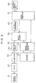
- Fig. 2 is a block diagram showing an embodiment of the present invention.
- Figs. 3, 4 and 6 are flowcharts for explaining the system shown in Fig. 3.
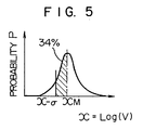
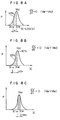
- Figs. 5 and 8A to 8C are diagrams showing distribution characteristics of the knock intensity value V.
- Fig. 7 is a flowchart for explaining the operation of a modification of the system according to the present invention.
- Fig. 9 is a flowchart showing details of the decision routine in Figs. 4 and 6.
- FIG. 2 A system according to the present invention is schematically shown in Fig. 2.
- Reference numeral 10 designates a knock sensor for detecting a knock generated in an engine, numeral 20 a filter for extracting a knock-related component from a signal of the knock sensor, numeral 30 an amplifier for amplifying the signal after being passed through the filter, numeral 40 a peak hold circuit, numeral 50 a multiplexer for selecting an input signal to an A/D converter, numeral 60 an A/D converter for converting an analog signal into a digital signal, numeral 70 a microcomputer for computing an ignition timing, amount of fuel injection, etc. on the basis of the information obtained from various sensors including the knock sensor, numeral 80 an ignitor, injector or the like for realizing the result of computation.
- Numeral 90 designates various sensors such as a crank angle sensor, intake air amount sensor or water temperature sensor, and character AO a signal processing circuit for processing signals produced from the sensors.
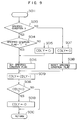
- FIG. 3 A flowchart for preparing a knock decision level V KD and making a knock decision is shown in Fig. 3.
- This routine starts with step S00, followed by step S01 for detecting a knock intensity value V.
- the knock intensity value V is, for example, a peak hold value of a knock sensor signal within a predetermined crank angle.
- Step S02 makes a knock decision. If V ⁇ V KD , it is decided that there occurs a knock. In accordance with the result of this decision, the ignition timing or the like is controlled in a control region (such as a heavy load region).
- Step S03 decides whether the engine operating conditions meet specific conditions which are defined by any one or combination of the following conditions:
- step S04 updates the value S corresponding to the standard deviation of the log(V) distribution (as described in detail later).
- Step S05 updates the central value V M of the V distribution (as described in detail later).
- Step S06 prepares a knock decision level V KD from the equation shown below.
- V KD S3 x V M
- Step S04A tests to determine whether a counter CDLY (described in detail later) for deciding on a predetermined period is set to zero, and if the answer is "Yes", the process proceeds to step S041, while if the answer is "No", the process is passed to step S048 to end the routine.
- Step S041 decides whether V ⁇ V M . If the answer is "Yes”, the process proceeds to step S042, and if the answer is "No”, to step S044.
- Step S042 decides whether S x V ⁇ V M , and if the answer is "Yes", the process proceeds to step S043, while if the answer is "No”, the process is passed to step S044.
- Step S043 reduces the value S by ⁇ S.
- Step S044 counts up an S-updating counter C S by one.
- Step S045 decides whether C S ⁇ 3, and if the answer is "Yes", the process proceeds to step S046, and if the answer is "No", to step S048.
- Step S046 clears the counter C S .
- Step S047 increases the value S by ⁇ S. Step S048 ends the routine.
- step S05 An updating routine starts with step S21, and step S22 tests whether V is larger than V M . If the answer at this step is "Yes”, the process proceeds to step S23 for storing (V - V M ) in a RAM called DV. Step S24 tests whether CDLY is zero, and if the answer is "Yes”, the process proceeds to step S25, while if the answer is negative, the process is passed to step S26. Step S25 increases the value V M by DV M /8. Step S26, on the other hand, increases the V M by DV M /4.
- step S27 If the answer is "No” at step S22, the process proceeds to step S27, where it is tested whether V is smaller than V M , and if the answer is "Yes", the process proceeds to step S28, while if the answer is "No", step S2D is followed.
- Step S28 stores (V M - V) in DV.
- Step S29 tests to determine whether CDLY is zero, and if the answer is "Yes”, the process is passed to step S2A, while if the answer is negative, the process is passed to step S2B.
- Step S2A reduces V M by DV M /8, while step S2B decreases V M by DV M /4.
- Step S2C stores the data in DV in DV M .
- Step S2D ends this routine.
- the values S and V M are updated by cylinder.
- the knock decision level V KD can be set at the point +3 ⁇ in the log(V) distribution, and therefore even under a great change in V variance, a knock is decided erroneously only with a probability which is always as low as and is negligible.
- V KD a value corresponding to the point 3 ⁇ in the log(V) distribution
- V KD a value corresponding to the point 3 ⁇ in the log(V) distribution
- the decision level may be corrected by use of a constant.
- V KD S3 x C x V M (C: A constant set in accordance with the engine conditions or cylinder).
- the present invention may also be combined with the technique disclosed in U.S. Patent No. 4,617,895 effectively.
- An example of such a combination will be explained with reference to the flowchart of Fig. 7. This shows a process replacing the step S06 in Fig. 3 and other steps may be the same as mentioned above.
- step S0700 The main routine starts at step S0700, and step S071 computes the variable A as S3 + D.
- step S072 decides whether the engine operating conditions or a knock sensor signal has satisfied specified conditions, and if the answer is "Yes", the process proceeds to step S074, while if the answer is "No", the process is passed to step S078.
- the specified conditions are for example, that:
- Step S074 decides whether V ⁇ V M /A , and if the answer is "Yes", the process proceeds to step S075, while if the answer is negative, the process is passed to step S076.
- Step 075 increases D by ⁇ D.
- Step S076 decides whether V ⁇ V KD , and if the answer is affirmative, the process is passed to step S077, while the process proceeds to step S078 otherwise.
- Step 077 reduces D by 2 x ⁇ D. Step S078 ends the main routine.
- the value D is not necessarily positive but may be negative.
- Step S013 decides whether the engine is under specified conditions including any one or combination of the following:
Landscapes
- Engineering & Computer Science (AREA)
- Chemical & Material Sciences (AREA)
- Combustion & Propulsion (AREA)
- Physics & Mathematics (AREA)
- General Physics & Mathematics (AREA)
- Signal Processing (AREA)
- Mechanical Engineering (AREA)
- General Engineering & Computer Science (AREA)
- Combined Controls Of Internal Combustion Engines (AREA)
- Electrical Control Of Ignition Timing (AREA)
Description
- The present invention relates to what is called a knock control system (KCS) for detecting a knocking generated in an internal combustion engine and controlling knock control factors such as ignition timing and air-fuel ratio.
- Generally, a knock decision (discrimination) level VKD is prepared by multiplying an average value Vmean of knock sensor signals by a constant K. Such a knock control system poses the problem that the optimum value of the constant K changes dependently on differences of sensors involved in manufacture of them or with lapse of time, thereby making impossible accurate knock detection. In order to solve this problem, a system has been invented for correcting a knock decision level automatically on the basis of the form in which the knock sensor signal is distributed. The U.S. Patent Specification No. 4,617,895 and JP-A-62-267574 each discloses such a system.
- Even such a system, however, has the problem that the knock decision is made improperly before the decision level is corrected. The present inventors have studied the reason why accurate knock detection is impossible by the conventional systems of decision level preparation.
- According to U.S. Patent specificaton No. 4,617,895, signals generated by a knock sensor coupled to an internal combustion engine and representing a knock intensity value V, i.e. an effective quantity signal such as a maximum peak value within a predetermined section of the knock sensor signal, can be arranged in a frequency distribution pattern with respect to their maximum peak values. Such a frequency distribution pattern of maximum peak values can be developped into logarithmic transformation values LOG(V) thereof with respect to the transformation ratio


- In the Figure, characters (a) and (b) represent assumed distributions with small and large standard deviations (which may be replaced by the variances) of log(V) respectively. The standard deviation of log(V) is naturally subject to changes with differences of sensors involved in manufacture or with lapse of time. The standard deviation of log(V) is referred to because the standard deviation of the knock intensity value V is substantially meaningless among those assuming a logarithmic-normal distribution. This is also the case with the average value Vmean and the median value VM. These two values are completely different and coincide with each other only in normal distribution. The value VM is more significant for a knock sensor signal in a logarithmic-normal distribution. In the description that follows herein, therefore, a knock decision level will be prepared on the basis of the more significant value VM. If a decision level is prepared as


- Moreover, from document JP-A-62-267574, a technique of stabilizing increases of retard angles of ignition timings caused under generation of knocking is known, which cyclically effects a knock decision step in an average cycle of once per second, thereby decreasing a parameter value A, which is representative of a standard deviation, by subtracting therefrom a predetermined amount cyclically in accordance with said average cycle, and increasing said parameter value A by adding thereto said predetermined amount every time it is detected that a knock intensity value V is smaller than or equal to the relation of a knock intensity corresponding to a cumulative 50% point and said parameter value A, resulting in updating said parameter value A to a value closer to the standard deviation.
- The technique suggested in document JP-A-62-267574 is thus capable of meeting and absorbing the change in the variance of the log(V) distribution, since the knock decision level is determined by the parameter value A, which changes in accordance with the variance of the log(V) distribution, and the knock intensity corresponding to said cumulative 50% point according to the expression

- However, since the frequency at which the value A is updated is almost the same as that for knock decision, the rate of updating is low, resulting in that it takes a long time before a knock decision level is corrected to an optimum value.
- Therefore, it is the object of the present invention to obviate these problems and to provide a knock control system being capable of detecting the occurrence of knocking in an internal combustion engine fast and accurately.
- According to the present invention, this object is accomplished by means of the features recited in
claim 1. - In operation, the predetermined knock intensity value Vp, which corresponds to a cumulative percentage point, of the distribution of the substantially logarithmic conversion value of the knock intensity value V determined by the knock intensity value determining means is determined by the determining means for determining a predetermined knock intensity value, and a value S corresponding to the standard deviation of the substantially logarithmic conversion value of the knock intensity value V is determined by the standard deviation determining means. Then a knock decision level is prepared on the basis of the predetermined knock intensity value VP and the value S logarithmically related to the standard deviation. This knock decision level is compared with a knock intensity value at the knock decision means thereby to decide whether a knocking has occurred or not.
- According to an embodiment of the invention, the knock decision level VKD is preferably prepared as Sn x VP and updated in such a manner that the predetermined knock intensity value VP is a cumulative 50% point VM and the probability of attaining the relations

- According to another embodiment of the invention, the knock decision level VKD should better be prepared in the form of S³ x VM.
- According to a further embodiment of the invention, means is provided for correcting, by a predetermined constant, the knock decision level prepared on the basis of the value S corresponding to the standard deviation and the cumulative 50% point VM.
- Fig. 1 is a diagram showing a distribution characteristic plotted on the logarithmic-normal probability paper of a knock intensity value V.
- Fig. 2 is a block diagram showing an embodiment of the present invention.
- Figs. 3, 4 and 6 are flowcharts for explaining the system shown in Fig. 3.
- Figs. 5 and 8A to 8C are diagrams showing distribution characteristics of the knock intensity value V.
- Fig. 7 is a flowchart for explaining the operation of a modification of the system according to the present invention.
- Fig. 9 is a flowchart showing details of the decision routine in Figs. 4 and 6.
- A system according to the present invention is schematically shown in Fig. 2.
Reference numeral 10 designates a knock sensor for detecting a knock generated in an engine, numeral 20 a filter for extracting a knock-related component from a signal of the knock sensor,numeral 30 an amplifier for amplifying the signal after being passed through the filter, numeral 40 a peak hold circuit, numeral 50 a multiplexer for selecting an input signal to an A/D converter,numeral 60 an A/D converter for converting an analog signal into a digital signal, numeral 70 a microcomputer for computing an ignition timing, amount of fuel injection, etc. on the basis of the information obtained from various sensors including the knock sensor,numeral 80 an ignitor, injector or the like for realizing the result of computation. Numeral 90 designates various sensors such as a crank angle sensor, intake air amount sensor or water temperature sensor, and character AO a signal processing circuit for processing signals produced from the sensors. - A flowchart for preparing a knock decision level VKD and making a knock decision is shown in Fig. 3. This routine starts with step S00, followed by step S01 for detecting a knock intensity value V. The knock intensity value V is, for example, a peak hold value of a knock sensor signal within a predetermined crank angle. Step S02 makes a knock decision. If V ≧ VKD, it is decided that there occurs a knock. In accordance with the result of this decision, the ignition timing or the like is controlled in a control region (such as a heavy load region). Step S03 decides whether the engine operating conditions meet specific conditions which are defined by any one or combination of the following conditions:
- (1) The engine load exceeds a predetermined value ;
- (2) The engine speed is within a predetermined range;
- (3) The change rate of engine load is less than a predetermined value;
- (4) The value VM is within a predetermined range.
- If the answer at step S03 is "Yes", the process proceeds to step S04, while if the answer is "No", the process is passed to step S05. S04 updates the value S corresponding to the standard deviation of the log(V) distribution (as described in detail later). Step S05 updates the central value VM of the V distribution (as described in detail later). Step S06 prepares a knock decision level VKD from the equation shown below.


- The reason why S takes a value corresponding to the standard deviation of the log(V) distribution in the process shown in Fig. 4 will be explained with reference to Fig. 5. Assume that the central value xM of the distribution of


This indicates that the probability of being


S is thus converged to a value satisfying the condition
associated with KS = 0. The relations below thus hold.
point 3 σ in the log(V) distribution (3 x σ on the logarithmic axis is equivalent to S³ on the real number axis). - Now, the process of step S05 will be explained in detail with reference to Fig. 6. An updating routine starts with step S21, and step S22 tests whether V is larger than VM. If the answer at this step is "Yes", the process proceeds to step S23 for storing (V - VM) in a RAM called DV. Step S24 tests whether CDLY is zero, and if the answer is "Yes", the process proceeds to step S25, while if the answer is negative, the process is passed to step S26. Step S25 increases the value VM by DVM/8. Step S26, on the other hand, increases the VM by DVM/4. If the answer is "No" at step S22, the process proceeds to step S27, where it is tested whether V is smaller than VM, and if the answer is "Yes", the process proceeds to step S28, while if the answer is "No", step S2D is followed. Step S28 stores (VM - V) in DV. Step S29 tests to determine whether CDLY is zero, and if the answer is "Yes", the process is passed to step S2A, while if the answer is negative, the process is passed to step S2B. Step S2A reduces VM by DVM/8, while step S2B decreases VM by DVM/4. Step S2C stores the data in DV in DVM. Step S2D ends this routine. In the foregoing description, the values S and VM are updated by cylinder.
- According to this embodiment, the knock decision level VKD can be set at the point +3 σ in the log(V) distribution, and therefore even under a great change in V variance, a knock is decided erroneously only with a probability which is always as low as

and is negligible. - Instead of setting VKD to a value corresponding to the
point 3 σ in the log(V) distribution as in this embodiment, it may be changed between for example the point 3.5 σ and 2.5 σ as required. In such a case, the computation of Sn which is somewhat inconvenient may be accomplished by a method in which the results of computation of Sn (1.0 to 4.1 for n = 3.5) against the value S corresponding to the standard deviation in a given range (say, 1.0 to 1.5) are written in the ROM in advance and obtained by table search. This method is very effective in the case where the microcomputer requires a long time in multiplication process if the value of n is integral. - The S-updating counter which is set to 3 according to the present embodiment to correspond to the standard deviation of the log(V) distribution may alternatively be set to other values. If CS = 4, for example, S is updated in such a manner that

which is equivalent to a quantity corresponding to 0.67 σx (

it is possible to set a knock decision level atpoint 3 σ. - Also, the central value VM, which is used to prepare VKD according to the embodiment under consideration, may be replaced with other value of a cumulative percentage point. If the cumulative 16% point is V₁₆, for instance, it is possible to set to
point 3 σ for
- Further, in order to change the knock control level in accordance with the engine conditions or cylinders, the decision level may be corrected by use of a constant. For example, use

- It is also effective to limit the value S within a predetermined range as required.
- It is also effective to limit the knock decision level within a predetermined range as required.
- The logarithmic conversion of V, which is not applied to the present invention according to the embodiment under consideration, may be used for the present invention with equal effect. In such a case, the only difference is to use a different equation like

point 3 σ. - The present invention may also be combined with the technique disclosed in U.S. Patent No. 4,617,895 effectively. An example of such a combination will be explained with reference to the flowchart of Fig. 7. This shows a process replacing the step S06 in Fig. 3 and other steps may be the same as mentioned above.
- The main routine starts at step S0700, and step S071 computes the variable A as S³ + D. Step S072 decides whether the engine operating conditions or a knock sensor signal has satisfied specified conditions, and if the answer is "Yes", the process proceeds to step S074, while if the answer is "No", the process is passed to step S078. The specified conditions are for example, that:
- (i) The engine load exceeds a predetermined value;
- (ii) The engine speed is within a predetermined range;
- (iii) The rate at which the engine speed changes is lower than a predetermined value;
- (iv) The value VM is within a predetermined range.
- Step S074 decides whether

- As described above with reference to an embodiment, the present invention has effects as mentioned below.
- (1) In view of the fact that a knock decision level is prepared on the basis of the value S corresponding to the standard deviation of the log(V) distribution, an accurate knock decision is made possible against a change in V variance due to the variations in engine or knock sensor.
- (2) The value S may be updated more frequently (once for every three cycles as in the embodiment under consideration), and therefore a decision level may be corrected to a proper value quickly.
- (3) By conceiving an appropriate method of updating S, the value S works to correct any deviation of VM from a correct value which may occur e.g. during a transient period, thus permitting accurate knock detection under transient conditions.
- Although the present invention is an improvement of the techniques disclosed in U.S. Patent No. 4,617,895 and JP-A-62-267574, the features (2) and (3) mentioned above are specific to the present invention and not found in the above references.
- The effect (3) will in particular be explained additionally by use of Figs. 8A to 8C. When dV/dt is larger than zero as under acceleration, VM becomes somewhat smaller than the true value as shown in Fig. 8B. (Under steady condition, the value VM coincides with the true value as shown in Fig. 8A) If VM is at a cumulative 40% point, for example,

(V₅₀: true value of median value), and therefore if
is to be satisfied, S is corrected so that
that is, VM/S is converted to the cumulative 7% point. The cumulative 40% point and 7% point correspond to -0.25 σ and -1.47 point, respectively (as determined from the normal distribution table). Therefore, S is finally corrected to a quantity corresponding to +0.25 + 0.61 = 0.86 σ, and thus assumes a value smaller than the true value, thereby correcting the deviation of VM from the true value. - Now, a specified period decision routine by a counter CDLY used in the flowcharts of Figs. 4 and 6 will be explained in detail with reference to Fig. 9. This routine starts with step S011. Step S013 decides whether the engine is under specified conditions including any one or combination of the following:
- (1) The engine is in high load region.
- (2) The change in engine speed exceeds a predetermined value.
- (3) The engine speed is within a predetermined range.
If step S013 decides that the specified conditions are met, the process proceeds to step S014, while if the answer at step S017 is negative, the process is passed to step S017. Step 014 tests whether the specified condition flag is "1", and if the answer is "Yes", the process is passed to step S016, while if the answer is "No", the process proceeds to step S015. Step S015 sets a counter CDLY for deciding on a predetermined period to a predetermined value C₁. Step S016 sets a specified condition flag. Step S017 clears the counter CDLY. Step S018 resets the specified condition flag. Step S019 decrements the counter CDLY by one count. Step S01A tests whether CDLY is negative or not, and if the answer is "Yes", the process proceeds to step S01B, while if the answer is "No", the process is passed to step S01C. Step S01B guards the counter CDLY to zero. This routine ends at step S01C. In this way, the counter CDLY is kept at a count other than zero for a predetermined period from the time when the specified conditions are established.
Claims (10)
- A knock control system for an internal combustion engine, comprising
a knock sensor (10) for detecting a knocking of the internal combustion engine and for generating a knock detection signal,
knock intensity value determining means (S01) for determining a knock intensity value (V) effective for knock detection on the basis of said knock detection signal generated by the knock sensor within a predetermined crank angle,
knock decision means (S02) for deciding on the presence or absence of a knocking by comparing the detected knock intensity value (V) with a knock decision level (VKD),
knock control means (80) for controlling knock control factors in response to a result of decision from the comparison,
determining means (S05) for determining a predetermined knock intensity value (Vp) corresponding to a predetermined accumulation point of a distribution of logarithmically converted determined knock intensity values (V),
standard deviation determining means (S04) for determining within a standard deviation determination cycle a value (S) logarithmically related to the standard deviation of said distribution of said logarithmically converted knock intensity values (V), and
knock decision level generation means (S06) for generating and for updating said knock decision level (VKD) on the basis of said predetermined knock intensity value (Vp) and said value (S) logarithmically related to said standard deviation, said knock control system
being characterized in that
said standard deviation determining means (S04) includes means (S043, S047) for changing said value (S) logarithmically related to said standard deviation by a predetermined value (ΔS), wherein said changing is carried out in substantial accordance with the cycles of determination of said knock intensity value at intervals corresponding to a number of said cycles determined on the basis of said knock intensity value (V), said predetermined knock intensity value (Vp) and specified engine conditions. - A knock control system according to claim 1, characterized in that said changing of said value (S) is performed at every determination of said knock intensity value.
- A knock control system according to claim 1 or 2, characterized in that said knock decision level generation means (S06) generates said knock decision level (VKD) in accordance with the equation Sn x Vp (n: constant).
- A knock control system according to claim 1 or 2, characterized in that said predetermined knock intensity value is a central 50% probability value (VM) of said substantially logarithmic knock intensity distribution.
- A knock control system according to claim 4, characterized in that said standard deviation determining means updates said value (S) logarithmically related to said standard deviation so as to make the probability of attaining the relationship

- A knock control system according to claim 4, characterized in that said knock decision level generating means generates a knock decision level VKD in the form of S³xVM.
- A knock control system according to claim 4, characterized by further comprising correction means (S074 to S077) for correcting the knock decision level VKD generated on the basis of said 50% probability value (VM) and said value (S) logarithmically related to said standard deviation by a predetermined constant.
- A knock control system according to claim 1 or 2, characterized by further comprising engine condition detecting means (S013) for detecting that the engine enters said specified conditions, period decision means (S014 to S016, S019, S01A, S01B, S24, S29) for deciding whether a predetermined period has passed after detection of said specified conditions by said engine condition detecting means (S013), update quantity setting means (S25, S26, S2A, S2B) for setting a quantity used for updating said predetermined accumulation point depending on the result of decision obtained from said period decision means, update quantity increasing means (S26, S2B) for increasing said quantity used for updating said predetermined accumulation point only while said period decision means decides that said predetermined period has not passed, and updating means (S2C) for updating said predetermined accumulation point.
- A knock control system according to claim 8, characterized in that said engine condition detecting means (S013) detects that the engine is under acceleration as one of said specified conditions.
- A knock control system according to claim 8, characterized in that said engine condition detecting means (S013) detects as said specified conditions at least one of the conditions that the internal combustion engine is in a heavy load region, that the change in engine speed is more than a predetermined value, and that the engine speed is within a predetermined range.
Priority Applications (1)
| Application Number | Priority Date | Filing Date | Title |
|---|---|---|---|
| EP93104098A EP0550411B1 (en) | 1988-06-14 | 1989-06-12 | Knock control system for internal combustion engine |
Applications Claiming Priority (4)
| Application Number | Priority Date | Filing Date | Title |
|---|---|---|---|
| JP146588/88 | 1988-06-14 | ||
| JP14658888A JPH0778380B2 (en) | 1988-06-14 | 1988-06-14 | Knock control device for internal combustion engine |
| JP14788588A JP2605805B2 (en) | 1988-06-15 | 1988-06-15 | Knock control device for internal combustion engine |
| JP147885/88 | 1988-06-15 |
Related Child Applications (1)
| Application Number | Title | Priority Date | Filing Date |
|---|---|---|---|
| EP93104098.4 Division-Into | 1993-03-12 |
Publications (3)
| Publication Number | Publication Date |
|---|---|
| EP0346799A2 EP0346799A2 (en) | 1989-12-20 |
| EP0346799A3 EP0346799A3 (en) | 1990-05-02 |
| EP0346799B1 true EP0346799B1 (en) | 1995-12-20 |
Family
ID=26477387
Family Applications (2)
| Application Number | Title | Priority Date | Filing Date |
|---|---|---|---|
| EP89110598A Expired - Lifetime EP0346799B1 (en) | 1988-06-14 | 1989-06-12 | Knock control system for internal combustion engine |
| EP93104098A Expired - Lifetime EP0550411B1 (en) | 1988-06-14 | 1989-06-12 | Knock control system for internal combustion engine |
Family Applications After (1)
| Application Number | Title | Priority Date | Filing Date |
|---|---|---|---|
| EP93104098A Expired - Lifetime EP0550411B1 (en) | 1988-06-14 | 1989-06-12 | Knock control system for internal combustion engine |
Country Status (3)
| Country | Link |
|---|---|
| US (1) | US4993387A (en) |
| EP (2) | EP0346799B1 (en) |
| DE (2) | DE68925152T2 (en) |
Families Citing this family (23)
| Publication number | Priority date | Publication date | Assignee | Title |
|---|---|---|---|---|
| US5038735A (en) * | 1989-10-30 | 1991-08-13 | Mitsubishi Denki Kabushiki Kaisha | Knock suppression apparatus and method for a multi-cylinder internal combustion engine |
| KR940001935B1 (en) * | 1990-04-26 | 1994-03-11 | 미쓰비시덴키 가부시키가이샤 | Apparatus and method for controlling knocking in an internal combustion engine |
| US5146893A (en) * | 1990-05-18 | 1992-09-15 | Mitsubishi Denki K.K. | Apparatus for and a method of detecting combustion in an internal combustion engine |
| DE59008539D1 (en) * | 1990-05-28 | 1995-03-30 | Siemens Ag | Process for cylinder-selective knock control of internal combustion engines. |
| JPH04219465A (en) * | 1990-12-20 | 1992-08-10 | Nippondenso Co Ltd | Knocking control device for internal combustion engine |
| JPH04252840A (en) * | 1991-01-25 | 1992-09-08 | Nippondenso Co Ltd | Knocking controller for internal combustion engine |
| JPH04244933A (en) * | 1991-01-31 | 1992-09-01 | Fuji Heavy Ind Ltd | Device for detecting knocking of engine |
| GB2259365B (en) * | 1991-09-04 | 1995-08-02 | Nippon Denso Co | Knock control apparatus for an internal combustion engine |
| JP3084889B2 (en) * | 1992-03-12 | 2000-09-04 | 株式会社デンソー | Knock control device for internal combustion engine |
| US5404854A (en) * | 1992-10-12 | 1995-04-11 | Nippondenso Co., Ltd. | Knock control system for internal combustion engine |
| US5386722A (en) * | 1993-03-24 | 1995-02-07 | Ford Motor Company | Method and apparatus for statistically determining knock borderline and evaluating knock intensity in an internal combustion engine |
| US5483936A (en) * | 1994-07-05 | 1996-01-16 | Kerstein; Scott M. | Spark knock detection system for an internal combustion engine |
| US6832598B2 (en) * | 2000-10-12 | 2004-12-21 | Kabushiki Kaisha Moric | Anti-knocking device an method |
| JP4052230B2 (en) * | 2003-11-12 | 2008-02-27 | トヨタ自動車株式会社 | Internal combustion engine knock determination device |
| US6945229B1 (en) | 2004-08-31 | 2005-09-20 | Visteon Global Technologies, Inc. | System for engine knock control |
| JP4404811B2 (en) | 2005-06-28 | 2010-01-27 | トヨタ自動車株式会社 | Knocking state determination device |
| JP4756968B2 (en) * | 2005-09-16 | 2011-08-24 | 株式会社デンソー | Internal combustion engine knock determination device |
| ITBO20050789A1 (en) * | 2005-12-23 | 2007-06-24 | Ferrari Spa | METHOD FOR THE CONTROL OF THE IGNITION ADVANCE IN AN INTERNAL COMBUSTION ENGINE. |
| JP4229142B2 (en) * | 2006-06-21 | 2009-02-25 | トヨタ自動車株式会社 | Knock control device for internal combustion engine |
| JP4312213B2 (en) * | 2006-06-28 | 2009-08-12 | トヨタ自動車株式会社 | Internal combustion engine knock determination device |
| JP4680248B2 (en) * | 2007-11-13 | 2011-05-11 | トヨタ自動車株式会社 | Ignition timing control device and ignition timing control method for internal combustion engine |
| JP5561283B2 (en) * | 2012-01-11 | 2014-07-30 | 株式会社デンソー | Sensor signal processing device |
| JP5395201B2 (en) * | 2012-03-14 | 2014-01-22 | 三菱電機株式会社 | Knock control device for internal combustion engine |
Family Cites Families (14)
| Publication number | Priority date | Publication date | Assignee | Title |
|---|---|---|---|---|
| DE2605335A1 (en) * | 1976-02-11 | 1977-08-18 | Krupp Gmbh | Automatic IC engine knocking force measurement - uses sensor determining engine noise to estimate statistical moments of amplitude |
| JPS5951675B2 (en) * | 1979-07-31 | 1984-12-15 | 日産自動車株式会社 | Internal combustion engine control device |
| FR2471485A1 (en) * | 1979-12-10 | 1981-06-19 | Renault | ELECTRONIC ANGLE CORRECTION FOR ADVANCING IGNITION IN RELATION TO CLICKS AND MOTOR LOAD |
| JPS5732065A (en) * | 1980-08-01 | 1982-02-20 | Nippon Denso Co Ltd | Ignition timing controller for engine |
| JPS58180766A (en) * | 1982-04-15 | 1983-10-22 | Nippon Denso Co Ltd | Ignition timing controller for internal-combustion engine |
| DE3313036C2 (en) * | 1983-04-12 | 1997-02-13 | Bosch Gmbh Robert | Device for preventing knocking in internal combustion engines |
| US4633835A (en) * | 1983-06-03 | 1987-01-06 | Mitsubishi Denki Kabushiki Kaisha | Ignition timing control apparatus for engine |
| US4617895A (en) * | 1984-05-17 | 1986-10-21 | Nippondenso Co., Ltd. | Anti-knocking control in internal combustion engine |
| DE3523230A1 (en) * | 1984-06-29 | 1986-01-02 | Nissan Motor Co., Ltd., Yokohama, Kanagawa | DEVICE AND METHOD FOR REGULATING THE IGNITION TIMING IN AN INTERNAL COMBUSTION ENGINE |
| JPH0735773B2 (en) * | 1985-04-11 | 1995-04-19 | 日本電装株式会社 | Knotting control device for internal combustion engine |
| JPH0663497B2 (en) * | 1985-04-18 | 1994-08-22 | 日本電装株式会社 | Knotting control device for internal combustion engine |
| US4711212A (en) * | 1985-11-26 | 1987-12-08 | Nippondenso Co., Ltd. | Anti-knocking in internal combustion engine |
| JPH0689734B2 (en) * | 1986-05-14 | 1994-11-14 | 日本電装株式会社 | Knock control device for internal combustion engine |
| JPH06100172B2 (en) * | 1986-12-01 | 1994-12-12 | 日本電装株式会社 | Knotting control device for internal combustion engine |
-
1989
- 1989-06-12 EP EP89110598A patent/EP0346799B1/en not_active Expired - Lifetime
- 1989-06-12 DE DE68925152T patent/DE68925152T2/en not_active Expired - Lifetime
- 1989-06-12 DE DE68927833T patent/DE68927833T2/en not_active Expired - Lifetime
- 1989-06-12 EP EP93104098A patent/EP0550411B1/en not_active Expired - Lifetime
- 1989-06-13 US US07/366,509 patent/US4993387A/en not_active Expired - Lifetime
Also Published As
| Publication number | Publication date |
|---|---|
| DE68925152D1 (en) | 1996-02-01 |
| EP0550411B1 (en) | 1997-03-05 |
| EP0346799A2 (en) | 1989-12-20 |
| EP0346799A3 (en) | 1990-05-02 |
| EP0550411A3 (en) | 1993-11-10 |
| DE68927833T2 (en) | 1997-09-18 |
| DE68927833D1 (en) | 1997-04-10 |
| DE68925152T2 (en) | 1996-05-15 |
| US4993387A (en) | 1991-02-19 |
| EP0550411A2 (en) | 1993-07-07 |
Similar Documents
| Publication | Publication Date | Title |
|---|---|---|
| EP0346799B1 (en) | Knock control system for internal combustion engine | |
| EP0446376B1 (en) | Apparatus for controlling the occurrence of engine knocking | |
| EP1586881B1 (en) | Apparatus and method for controlling internal combustion engine | |
| EP0494423B1 (en) | System for detecting combustion state in internal combustion engine | |
| EP1924831B1 (en) | Knock determination apparatus and method for engines | |
| US6591660B1 (en) | Method for detecting knocking | |
| US5287837A (en) | Knock suppressing apparatus for internal combustion engine | |
| US4766545A (en) | System for controlling the ignition timing of an internal combustion engine | |
| US5190011A (en) | Knocking control method and apparatus for internal combustion engine | |
| EP2189643B1 (en) | Knocking detecting apparatus for internal combustion engine | |
| EP1586882A2 (en) | Knock determining apparatus and method for international combustion engine | |
| GB2055426A (en) | Device for controlling an internal combustion engine by detecting knock | |
| US4736723A (en) | System and method for controlling the ignition timing of an internal combustion engine | |
| US4715342A (en) | System for controlling the ignition timing of an internal combustion engine | |
| US4892075A (en) | Crank angle detecting system for internal combustion engines | |
| EP0096869B1 (en) | Method and apparatus of ignition timing control | |
| EP1896816B1 (en) | Knocking state determination device | |
| KR100347644B1 (en) | Method for detecting knocking | |
| US5188080A (en) | Knocking control system for internal combustion engine | |
| US4620518A (en) | System for controlling the ignition timing of an internal combustion engine | |
| EP0511220B1 (en) | Knock control system of a spark ignition internal combustion engine | |
| US4844027A (en) | System for controlling the ignition timing of an internal combustion engine | |
| US5215058A (en) | Knock control apparatus for internal combustion engines | |
| US4269154A (en) | Ignition timing control system for internal combustion engines | |
| JP2605805B2 (en) | Knock control device for internal combustion engine |
Legal Events
| Date | Code | Title | Description |
|---|---|---|---|
| PUAI | Public reference made under article 153(3) epc to a published international application that has entered the european phase |
Free format text: ORIGINAL CODE: 0009012 |
|
| AK | Designated contracting states |
Kind code of ref document: A2 Designated state(s): DE FR GB IT |
|
| PUAL | Search report despatched |
Free format text: ORIGINAL CODE: 0009013 |
|
| AK | Designated contracting states |
Kind code of ref document: A3 Designated state(s): DE FR GB IT |
|
| 17P | Request for examination filed |
Effective date: 19900713 |
|
| 17Q | First examination report despatched |
Effective date: 19920903 |
|
| GRAA | (expected) grant |
Free format text: ORIGINAL CODE: 0009210 |
|
| AK | Designated contracting states |
Kind code of ref document: B1 Designated state(s): DE FR GB IT |
|
| XX | Miscellaneous (additional remarks) |
Free format text: TEILANMELDUNG 93104098.4 EINGEREICHT AM 12/06/89. |
|
| REF | Corresponds to: |
Ref document number: 68925152 Country of ref document: DE Date of ref document: 19960201 |
|
| ITF | It: translation for a ep patent filed | ||
| ET | Fr: translation filed | ||
| PLBE | No opposition filed within time limit |
Free format text: ORIGINAL CODE: 0009261 |
|
| STAA | Information on the status of an ep patent application or granted ep patent |
Free format text: STATUS: NO OPPOSITION FILED WITHIN TIME LIMIT |
|
| 26N | No opposition filed | ||
| REG | Reference to a national code |
Ref country code: GB Ref legal event code: 746 Effective date: 19970116 |
|
| ITPR | It: changes in ownership of a european patent |
Owner name: OFFERTA DI LICENZA AL PUBBLICO;AL PUBBLICO |
|
| ITPR | It: changes in ownership of a european patent |
Owner name: OFFERTA DI LICENZA AL PUBBLICO;PUBBLICO |
|
| REG | Reference to a national code |
Ref country code: GB Ref legal event code: IF02 |
|
| PGFP | Annual fee paid to national office [announced via postgrant information from national office to epo] |
Ref country code: IT Payment date: 20080624 Year of fee payment: 20 |
|
| PGFP | Annual fee paid to national office [announced via postgrant information from national office to epo] |
Ref country code: DE Payment date: 20080619 Year of fee payment: 20 |
|
| PGFP | Annual fee paid to national office [announced via postgrant information from national office to epo] |
Ref country code: FR Payment date: 20080617 Year of fee payment: 20 |
|
| PGFP | Annual fee paid to national office [announced via postgrant information from national office to epo] |
Ref country code: GB Payment date: 20080618 Year of fee payment: 20 |
|
| REG | Reference to a national code |
Ref country code: GB Ref legal event code: PE20 Expiry date: 20090611 |
|
| PG25 | Lapsed in a contracting state [announced via postgrant information from national office to epo] |
Ref country code: GB Free format text: LAPSE BECAUSE OF EXPIRATION OF PROTECTION Effective date: 20090611 |