EP0346779B1 - Projectile for practice - Google Patents
Projectile for practice Download PDFInfo
- Publication number
- EP0346779B1 EP0346779B1 EP89110510A EP89110510A EP0346779B1 EP 0346779 B1 EP0346779 B1 EP 0346779B1 EP 89110510 A EP89110510 A EP 89110510A EP 89110510 A EP89110510 A EP 89110510A EP 0346779 B1 EP0346779 B1 EP 0346779B1
- Authority
- EP
- European Patent Office
- Prior art keywords
- projectile
- cap
- projectile body
- hood
- training
- Prior art date
- Legal status (The legal status is an assumption and is not a legal conclusion. Google has not performed a legal analysis and makes no representation as to the accuracy of the status listed.)
- Expired - Lifetime
Links
Images
Classifications
-
- F—MECHANICAL ENGINEERING; LIGHTING; HEATING; WEAPONS; BLASTING
- F42—AMMUNITION; BLASTING
- F42B—EXPLOSIVE CHARGES, e.g. FOR BLASTING, FIREWORKS, AMMUNITION
- F42B8/00—Practice or training ammunition
- F42B8/12—Projectiles or missiles
- F42B8/14—Projectiles or missiles disintegrating in flight or upon impact
Definitions
- the invention relates to a training projectile according to the preamble of claim 1.
- a self-supporting hood made of plastic is provided. This hood withstands the forces exerted on the projectile during launch and in flight. However, due to the stability of the hood, there is a risk that the projectile will bounce off the sand floor practically undamaged at flat angles of impact and then fly over the safety area of the shooting range.
- the object of the invention is to propose a training projectile, the hood of which on the one hand withstands the loads occurring during the feeding and the firing and on the other hand the bounce range is reduced.
- the support member stabilizes the thin-walled hood axially and radially so that it can withstand the forces that occur during feeding and firing. On the other hand, even at flat angles of incidence and low impingement speeds, the support part deforms so that the hood breaks off. This increases the flow resistance of the parts so that the bounce range is reduced.
- Another advantage of this practice floor is that a particularly thin-walled, inexpensive hood can be used, since its stability, which is low in itself, is increased by the support part.
- a practice projectile has a projectile body (1) made of steel, which is provided with a guide band (2).
- the projectile body (1) is provided with steps (3) on the front side and, viewed in isolation, has a high air resistance.
- the projectile body (1) is provided with an axial bore (4).
- the projectile body (1) On the projectile body (1) is a comparative screwed thin-walled ogiven-shaped hood (5), which consists for example of aluminum.
- the projectile body (1) forms together with the hood (5) a projectile whose ballistic values correspond to those of sharp projectiles.
- a support part (7) is arranged in this.
- the support part (7) is made of plastic, such as polyethylene, polyurethane or polyamide.
- the support part (7) has a pin (8) which is inserted into the bore (4).
- the support part (7) is provided with four webs (9) which are arranged in a star shape (see FIG. 3). Only three webs (9) or more than four webs (9) can also be provided.
- the webs (9) have outer edges (10), on the course of which the inner shape of the hood (5) is adapted.
- the webs (9) rest with rear edges (11) in the vicinity of the pin (8) on the front of the projectile body (1).
- the functionality of the described device is approximately as follows:
- the support part (7) is held radially by the pin (8) on the projectile body (1). It is supported axially on the rear edges (11) of its webs (9).
- the outer edges (10) support the hood (5) both radially and axially.
- the supporting part (7) takes on axial and radial forces acting on the hood (5).
- the support part (7) also dampens vibrations of the hood (5).
- the webs (9) are deformed on account of the elasticity of the plastic and their shape, so that the hood (5) breaks off from the projectile body (1).
- the then effective air resistance of the projectile body (1) is so high that the projectile body (1) flies only a comparatively small distance.
- surface parts can be arranged in the area of its steps or on the support part (7), which open or open when the hood (5) is broken off.
Description
Die Erfindung betrifft ein Übungsgeschoß nach dem Oberbegriff des Anspruches 1.The invention relates to a training projectile according to the preamble of
Bei einem bekannten Übungsgeschoß gemäß der DE-A 26 39 884 ist eine selbsttragende Haube aus Kunststoff vorgesehen. Diese Haube hält den auf das Geschoß beim Abschuß und während des Fluges einwirkenden Kräften stand. Jedoch besteht aufgrund der Stabilität der Haube die Gefahr, daß das Geschoß bei flachen Auftreffwinkeln auf Sandboden praktisch unbeschädigt vom Sandboden abprallt und dann über den Sicherheitsbereich des Schießplatzes hinausfliegt.In a known practice floor according to DE-A 26 39 884, a self-supporting hood made of plastic is provided. This hood withstands the forces exerted on the projectile during launch and in flight. However, due to the stability of the hood, there is a risk that the projectile will bounce off the sand floor practically undamaged at flat angles of impact and then fly over the safety area of the shooting range.
Die Haube bzw. deren Anordnung am Geschoßkörper so schwach auszubilden, daß sie auch bei einem flachen Zielaufprall zerstört wird, verbietet sich, da sie dann den bei der Zuführung zum Waffenrohr und beim Abschuß auftretenden Belastungen nicht mehr standhält.It is forbidden to design the hood or its arrangement on the projectile body so weakly that it is destroyed even in the event of a flat target impact, since it then no longer withstands the loads that occur when it is fed to the weapon barrel and when it is fired.
Aufgabe der Erfindung ist es, ein Übungsgeschoß vorzuschlagen, dessen Haube einerseits den bei der Zuführung und beim Abschuß auftretenden Belastungen standhält und dessen Abprallreichweite andererseits vermindert ist.The object of the invention is to propose a training projectile, the hood of which on the one hand withstands the loads occurring during the feeding and the firing and on the other hand the bounce range is reduced.
Erfindungsgemäß ist obige Aufgabe bei einem Übungsgeschoß entsprechend den kennzeichnenden Merkmalen des Anspruches 1 gelöst.According to the invention, the above object is achieved in a practice projectile in accordance with the characterizing features of
Das Stützteil stabilisiert die dünnwandige Haube axial und radial so, daß sie den bei der Zuführung und beim Abschuß auftretenden Kräften standhält. Andererseits verformt sich auch bei flachen Auftreffwinkeln und geringen Auftreffgeschwindigkeiten das Stützteil so, daß die Haube abbricht. Dadurch erhöht sich der Strömungswiderstand der Teile, so daß die Abprallreichweite vermindert ist.The support member stabilizes the thin-walled hood axially and radially so that it can withstand the forces that occur during feeding and firing. On the other hand, even at flat angles of incidence and low impingement speeds, the support part deforms so that the hood breaks off. This increases the flow resistance of the parts so that the bounce range is reduced.
Ein weiterer Vorteil dieses Übungsgeschosses besteht auch darin, daß eine besonders dünnwandige, billige Haube verwendet werden kann, da deren an sich geringe Stabilität durch das Stützteil erhöht ist.Another advantage of this practice floor is that a particularly thin-walled, inexpensive hood can be used, since its stability, which is low in itself, is increased by the support part.
Vorteilhafte Ausgestaltungen der Erfindung ergeben sich aus den Unteransprüchen und der folgenden Beschreibung eines Ausführungsbeispiels. In der Zeichnung zeigen:
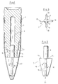
Figur 1 ein Übungsgeschoß im Schnitt,- Figur 2 eine Ansicht des Stützteils entsprechend
Figur 1 und Figur 3 eine Ansicht des Stützteils in Richtung des Pfeiles III nach Figur 2.
- FIG. 1 shows an average practice floor,
- Figure 2 is a view of the support member corresponding to Figure 1 and
- Figure 3 is a view of the support member in the direction of arrow III of Figure 2.
Ein Übungsgeschoß weist einen Geschoßkörper(1) aus Stahl auf, der mit einem Führungsband(2) versehen ist. Der Geschoßkörper(1) ist frontseitig mit Stufen(3) versehen und weist für sich betrachtet einen hohen Luftwiderstand auf. Der Geschoßkörper(1) ist mit einer axialen Bohrung(4) versehen.A practice projectile has a projectile body (1) made of steel, which is provided with a guide band (2). The projectile body (1) is provided with steps (3) on the front side and, viewed in isolation, has a high air resistance. The projectile body (1) is provided with an axial bore (4).
Auf den Geschoßkörper(1) ist eine vergleichsweise dünnwandige, ogivenförmige Haube(5) aufgeschraubt, welche beispielsweise aus Aluminium besteht. Der Geschoßkörper(1) bildet zusammen mit der Haube(5) ein Geschoß, dessen ballistische Werte denen von scharfen Geschossen entsprechen. Zwischen der Haube(5) und der Frontseite des Geschoßkörpers(1) besteht ein Freiraum(6). In diesem ist ein Stützteil(7) angeordnet. Das Stützteil(7) besteht aus Kunststoff, wie beispielsweise Polyäthylen, Polyurethan oder Polyamid.On the projectile body (1) is a comparative screwed thin-walled ogiven-shaped hood (5), which consists for example of aluminum. The projectile body (1) forms together with the hood (5) a projectile whose ballistic values correspond to those of sharp projectiles. There is a free space (6) between the hood (5) and the front of the projectile body (1). A support part (7) is arranged in this. The support part (7) is made of plastic, such as polyethylene, polyurethane or polyamide.
Das Stützteil(7) weist einen Zapfen(8) auf, welcher in die Bohrung(4) eingesteckt ist. Das Stützteil(7) ist mit vier Stegen(9) versehen, die sternförmig (vgl. Figur 3) angeordnet sind. Es können auch nur drei Stege(9) oder mehr als vier Stege(9) vorgesehen sein.The support part (7) has a pin (8) which is inserted into the bore (4). The support part (7) is provided with four webs (9) which are arranged in a star shape (see FIG. 3). Only three webs (9) or more than four webs (9) can also be provided.
Die Stege(9) weisen Außenränder(10), auf deren Verlauf der Innengestalt der Haube(5) angepaßt ist. Die Stege(9) liegen mit heckseitigen Rändern(11) in der Umgebung des Zapfens(8) an der Frontseite des Geschoßkörpers(1) an.The webs (9) have outer edges (10), on the course of which the inner shape of the hood (5) is adapted. The webs (9) rest with rear edges (11) in the vicinity of the pin (8) on the front of the projectile body (1).
Die Funktionsweise der beschriebenen Einrichtung ist etwa folgende:
Das Stützteil(7) ist durch den Zapfen(8) am Geschoßkörper(1) radial gehalten. Es stützt sich an diesem axial über die heckseitigen Ränder(11) seiner Stege(9) ab. Die Außenränder(10) stützen die Haube(5) sowohl radial als auch axial.The functionality of the described device is approximately as follows:
The support part (7) is held radially by the pin (8) on the projectile body (1). It is supported axially on the rear edges (11) of its webs (9). The outer edges (10) support the hood (5) both radially and axially.
Bei der Zuführung des Geschosses zum Waffenrohr und beim Abschuß, sowie im Flug übernimmt das Stützteil(7) auf die Haube(5) wirkende axiale und radiale Kräfte. Das Stützteil(7) dämpft auch Schwingungen der Haube(5).When the projectile is fed to the weapon barrel and when it is launched, as well as in flight, the supporting part (7) takes on axial and radial forces acting on the hood (5). The support part (7) also dampens vibrations of the hood (5).
Beim Aufprall, insbesondere auch beim flachen Zielaufprall werden die Stege(9) aufgrund der Elastizität des Kunststoffs und deren Formgestaltung verformt, so daß die Haube(5) vom Geschoßkörper(1) abbricht. Der dann wirksame Luftwiderstand des Geschoßkörpers(1) ist so hoch, daß der Geschoßkörper(1) nur noch eine vergleichsweise kleine Strecke weiterfliegt.In the event of an impact, in particular also in the case of a flat target impact, the webs (9) are deformed on account of the elasticity of the plastic and their shape, so that the hood (5) breaks off from the projectile body (1). The then effective air resistance of the projectile body (1) is so high that the projectile body (1) flies only a comparatively small distance.
Zur weiteren Vergrößerung des Luftwiderstands des Geschoßkörpers(1) können im Bereich von dessen Stufen oder am Stützteil(7) Flächenteile angeordnet sein, die beim Abbrechen der Haube(5) aufspringen oder aufklappen.To further increase the air resistance of the projectile body (1), surface parts can be arranged in the area of its steps or on the support part (7), which open or open when the hood (5) is broken off.
Claims (4)
- A training projectile with a thin-walled ogival cap (5) made of plastics material, which is superimposed onto a projectile body (1), the projectile body (1) has inside the ballistic cap (5) steps (3) and an axial bore (4) into which is inserted a pin (8) of a supplementary body (7), in which respect the supplementary body (7) lies in a free space (6) between the projectile body (1) and the cap (5), characterised in that the supplementary body is a supporting part (7) made of plastics material having arms (9) arranged in a star-shaped manner, the outer edges (10) of which butt against the cap (5) and the front side of the projectile body (1) is designed in such a way that its air resistance is high in comparison with the projectile.
- A training projectile according to claim 1, characterised in that the supporting part (7) butts with tail-sided edges (11) of the arms (9) in the vicinity of the pin (8) against the projectile body (1).
- A training projectile according to claim 1, characterised in that provided on the projectile body (1) or on the supporting part (7) are surface parts which after the breaking-off of the cap (5) increase the air resistance.
- A training projectile according to claim 1, characterised in that the outer edges (10) of the arms (9) butt over their entire length against the cap (5) and support this axially and radially.
Applications Claiming Priority (2)
| Application Number | Priority Date | Filing Date | Title |
|---|---|---|---|
| DE8807701U | 1988-06-14 | ||
| DE8807701U DE8807701U1 (en) | 1988-06-14 | 1988-06-14 |
Publications (2)
| Publication Number | Publication Date |
|---|---|
| EP0346779A1 EP0346779A1 (en) | 1989-12-20 |
| EP0346779B1 true EP0346779B1 (en) | 1992-10-28 |
Family
ID=6825003
Family Applications (1)
| Application Number | Title | Priority Date | Filing Date |
|---|---|---|---|
| EP89110510A Expired - Lifetime EP0346779B1 (en) | 1988-06-14 | 1989-06-10 | Projectile for practice |
Country Status (2)
| Country | Link |
|---|---|
| EP (1) | EP0346779B1 (en) |
| DE (2) | DE8807701U1 (en) |
Families Citing this family (1)
| Publication number | Priority date | Publication date | Assignee | Title |
|---|---|---|---|---|
| US5116224A (en) * | 1990-06-25 | 1992-05-26 | Kelsey Jr Charles C | Devel small arms bullet |
Family Cites Families (8)
| Publication number | Priority date | Publication date | Assignee | Title |
|---|---|---|---|---|
| DE1216736B (en) * | 1964-04-23 | 1966-05-12 | Dynamit Nobel Ag | Decay projectile for maneuver ammunition |
| CH532240A (en) * | 1970-12-08 | 1972-12-31 | Oerlikon Buehrle Ag | Short course floor |
| DE2639884A1 (en) * | 1976-09-04 | 1978-03-09 | Dynamit Nobel Ag | BULLET FOR PRACTICE AMMUNITION |
| DE2641021A1 (en) * | 1976-09-11 | 1978-03-23 | Rheinmetall Gmbh | PRACTICE FLOOR |
| AT364625B (en) * | 1979-11-29 | 1981-11-10 | Semperit Ag | EXERCISE SHOOTING SHOOTING POINT |
| BE882272A (en) * | 1980-03-18 | 1980-09-18 | Herstal Sa | TRAINING AMMUNITION |
| US4465464A (en) * | 1983-02-03 | 1984-08-14 | Schoenberg George R | Ballistic missile structure simulator |
| US4589342A (en) * | 1985-02-28 | 1986-05-20 | The United States Of America As Represented By The Secretary Of The Navy | Rocket-powered training missile with impact motor splitting device |
-
1988
- 1988-06-14 DE DE8807701U patent/DE8807701U1/de not_active Expired
-
1989
- 1989-06-10 EP EP89110510A patent/EP0346779B1/en not_active Expired - Lifetime
- 1989-06-10 DE DE8989110510T patent/DE58902540D1/en not_active Expired - Fee Related
Also Published As
| Publication number | Publication date |
|---|---|
| DE58902540D1 (en) | 1992-12-03 |
| DE8807701U1 (en) | 1989-10-12 |
| EP0346779A1 (en) | 1989-12-20 |
Similar Documents
| Publication | Publication Date | Title |
|---|---|---|
| DE1578191A1 (en) | Sabot bullet | |
| EP3060875B1 (en) | Cartridge | |
| DE2537116A1 (en) | BULLET OR GUIDE RING FOR A SUB-CALIBER BULLET | |
| EP0069949B1 (en) | Projectile assembly for a barrel-type weapon | |
| DE2340652A1 (en) | GUN | |
| DE1240443B (en) | Device for adjusting the range of missiles | |
| DE2039719A1 (en) | Sabot bullet, especially arrow bullet | |
| EP0315125A2 (en) | Sabot projectile for an insert barrel | |
| DE1148161B (en) | Sealing ring made of plastic material, mounted in the annular groove of a projectile body | |
| DE69727518T2 (en) | Bullet with a high degree of deformation upon impact | |
| DE3833001A1 (en) | SUB-CALIBRAL AMMUNITION | |
| EP0346779B1 (en) | Projectile for practice | |
| DE3418444A1 (en) | ARMORED BULLET | |
| DE3408476A1 (en) | FULL-CALIBRATION TRAINING FLOOR | |
| CH658905A5 (en) | Twist-stabilized practice floor. | |
| DE3233044A1 (en) | AMMUNITION UNIT, PREFERABLY FOR EXERCISE PURPOSES | |
| DE19650740C2 (en) | Sub-caliber floor | |
| DE2364926A1 (en) | SHELTER FLOOR WITH STABILIZED ROTATION | |
| DE2726551C2 (en) | ||
| DE2131084C3 (en) | Floating floor | |
| DE4037451C2 (en) | Compressed gas firearm for diabolos, especially rifles or handguns | |
| DE3016638C1 (en) | Splinter-forming projectile | |
| DE19835173B4 (en) | Subcaliber balancing projectile | |
| DE1428690C (en) | Rifle bullet | |
| DE102012006895B3 (en) | Control surface-stabilized full caliber-practice projectile has solid head portion and annular control surface body that is adjoined to rear side of head part, where practice projectile is circumferentially provided with sealing system |
Legal Events
| Date | Code | Title | Description |
|---|---|---|---|
| PUAI | Public reference made under article 153(3) epc to a published international application that has entered the european phase |
Free format text: ORIGINAL CODE: 0009012 |
|
| AK | Designated contracting states |
Kind code of ref document: A1 Designated state(s): DE GB IT SE |
|
| 17P | Request for examination filed |
Effective date: 19891111 |
|
| 17Q | First examination report despatched |
Effective date: 19910531 |
|
| GRAA | (expected) grant |
Free format text: ORIGINAL CODE: 0009210 |
|
| AK | Designated contracting states |
Kind code of ref document: B1 Designated state(s): DE GB IT SE |
|
| PG25 | Lapsed in a contracting state [announced via postgrant information from national office to epo] |
Ref country code: SE Effective date: 19921028 |
|
| REF | Corresponds to: |
Ref document number: 58902540 Country of ref document: DE Date of ref document: 19921203 |
|
| GBT | Gb: translation of ep patent filed (gb section 77(6)(a)/1977) |
Effective date: 19921214 |
|
| ITF | It: translation for a ep patent filed |
Owner name: STUDIO JAUMANN |
|
| PGFP | Annual fee paid to national office [announced via postgrant information from national office to epo] |
Ref country code: GB Payment date: 19930607 Year of fee payment: 5 |
|
| PGFP | Annual fee paid to national office [announced via postgrant information from national office to epo] |
Ref country code: DE Payment date: 19930818 Year of fee payment: 5 |
|
| PLBE | No opposition filed within time limit |
Free format text: ORIGINAL CODE: 0009261 |
|
| STAA | Information on the status of an ep patent application or granted ep patent |
Free format text: STATUS: NO OPPOSITION FILED WITHIN TIME LIMIT |
|
| 26N | No opposition filed | ||
| PG25 | Lapsed in a contracting state [announced via postgrant information from national office to epo] |
Ref country code: GB Effective date: 19940610 |
|
| GBPC | Gb: european patent ceased through non-payment of renewal fee |
Effective date: 19940610 |
|
| PG25 | Lapsed in a contracting state [announced via postgrant information from national office to epo] |
Ref country code: DE Effective date: 19950301 |
|
| PG25 | Lapsed in a contracting state [announced via postgrant information from national office to epo] |
Ref country code: IT Free format text: LAPSE BECAUSE OF NON-PAYMENT OF DUE FEES Effective date: 20050610 |