EP0346778B1 - Residue removal process - Google Patents
Residue removal process Download PDFInfo
- Publication number
- EP0346778B1 EP0346778B1 EP89110508A EP89110508A EP0346778B1 EP 0346778 B1 EP0346778 B1 EP 0346778B1 EP 89110508 A EP89110508 A EP 89110508A EP 89110508 A EP89110508 A EP 89110508A EP 0346778 B1 EP0346778 B1 EP 0346778B1
- Authority
- EP
- European Patent Office
- Prior art keywords
- mixing
- rubber
- extractant
- hydrogenated nitrile
- kneading
- Prior art date
- Legal status (The legal status is an assumption and is not a legal conclusion. Google has not performed a legal analysis and makes no representation as to the accuracy of the status listed.)
- Expired - Lifetime
Links
Images


Classifications
-
- C—CHEMISTRY; METALLURGY
- C08—ORGANIC MACROMOLECULAR COMPOUNDS; THEIR PREPARATION OR CHEMICAL WORKING-UP; COMPOSITIONS BASED THEREON
- C08C—TREATMENT OR CHEMICAL MODIFICATION OF RUBBERS
- C08C2/00—Treatment of rubber solutions
- C08C2/02—Purification
-
- C—CHEMISTRY; METALLURGY
- C08—ORGANIC MACROMOLECULAR COMPOUNDS; THEIR PREPARATION OR CHEMICAL WORKING-UP; COMPOSITIONS BASED THEREON
- C08C—TREATMENT OR CHEMICAL MODIFICATION OF RUBBERS
- C08C19/00—Chemical modification of rubber
- C08C19/02—Hydrogenation
Definitions
- This invention relates to a process to extract residue from hydrogenated nitrile rubber (HNBR).
- HNBR hydrogenated nitrile rubber
- EP-A-0 262 594 discloses a process for removing substantial quantities of volatile liquid, e.g. hydrocarbon from a mixture of polymer and such liquid is provided.
- This process consists of the initial step of introducing the mixture, and a liquid which is immiscible with the polymer, into a mixing/kneading zone provided with heated heat transfer surfaces having a temperature higher than the boiling point of the lowest boiling liquid component in the mixing/kneading zone.
- the mixture and the immiscible liquid are subjected to a period of continuous mixing and kneading within the mixing/kneading zone, to bring the mixture into continuously moving contact with the heat transfer surfaces.
- the heated heat transfer surfaces are repeatedly mechanically cleaned to prevent buildup of solid polymer thereon.
- Volatilized liquid is vented from the mixing/kneading zone during the period of continuous mixing and kneading, and the polymer and residual liquid is subsequently discharged from the mixing/kneading zone.
- the process technology as generally described herein may be suitable for the extraction of a wide variety of residues (for example, residual solvent, residual monomer, residual catalyst) from a wide variety of rubbers (such as butyl rubber and its halogenated derivatives, acrylonitrile-butadiene rubber, ethylene-propylene copolymers and terpolymers, and polybutadiene), the present invention relates solely to a process to extract residue from hydrogenated nitrile rubber.
- residues for example, residual solvent, residual monomer, residual catalyst
- rubbers such as butyl rubber and its halogenated derivatives, acrylonitrile-butadiene rubber, ethylene-propylene copolymers and terpolymers, and polybutadiene
- the extractant liquid is essential to the present process. Whilst it is not intended that the invention should be limited by any particular theory, it is believed that the extractant becomes dispersed throughout the rubber (without substantially dissolving the rubber) during the mixing/kneading process.
- the extractant liquid extracts residue from the hydrogenated nitrile rubber during the mixing and kneading step.
- the extractant liquid, containing residue, is then separated from the hydrogenated nitrile rubber.
- the extractant liquid must be miscible with at least part of the residue contained in the hydrogenated nitrile rubber.
- the extractant must not be a good solvent for the rubber.
- Suitable examples of the extractant liquid include lower alcohols (such as methanol and ethanol), acetonitrile, and perchloroethylene. More than one extractant may be employed.
- hydrogenated nitrile rubber refers to the product which is obtained by hydrogenating an unsaturated polymer of a C3 ⁇ 5, , ⁇ unsaturated nitrile and a C4 ⁇ 6 conjugated diene (for example, acrylonitrile-butadiene rubber).
- Hydrogenated nitrile rubbers are sold under the tradename ZETPOL® by Nippon Zeon. A process to prepare hydrogenated nitrile rubber is described in U.K. Patent 1,558,491.
- hydrogenated nitrile rubber may contain residue remaining from the hydrogenation process, such as residual catalyst, residual co-catalyst, residual solvent and/or residue which may have been contained within the nitrile rubber prior to hydrogenation.
- residue remaining from the hydrogenation process such as residual catalyst, residual co-catalyst, residual solvent and/or residue which may have been contained within the nitrile rubber prior to hydrogenation.
- solvent-free process meaning that no solvent for the rubber is added during the process
- a minor amount of solvent may be contained within the rubber as a residue.
- Residue is removed from hydrogenated nitrile rubber in the present process with the assistance of an extractant liquid.
- the amount of extractant employed is from 20 to 500 parts by weight per 100 parts by weight rubber, preferably from 20 to 200 parts by weight of methanol.
- a chelating agent such as thiourea or alkyl bromide.
- the extractant fluid contains thiourea it is preferred to complete the process at a temperature of between 50° and 60°C and atmospheric pressure.
- the mixing/kneading zone into which the hydrogenated nitrile rubber and extractant liquid are introduced is suitably an apparatus equipped with mixing/kneading elements to which the rubber/liquid mixture is brought into continuously moving contact.
- the function of the mixing/kneading elements is to ensure continuous intimate mixing of the mixture in the zone, and to ensure that the mixture is in continuously moving contact with the mixing surfaces. It is believed that the mixing generates new rubber surfaces which assist with mass transfer of residue from the rubber to the extractant liquid. There is preferably no dead-space within the mixing/kneading zone.
- the apparatus constituting the mixing/kneading zone is in the form of a stationary drum, equipped with rotary mixing/kneading elements arranged to wipe continuously against the interior of the boundary walls as they rotate and perform their mixing/kneading function.
- the boundary walls and/or the mixing/kneading elements may be heated. In this way the rotary mixing/kneading elements serve to clean the mixing zone walls as they mix and knead.
- These mixing/kneading elements can be paddles, arms, bars, discs, disc segments, pins or combination thereof. These elements are preferably mounted on at least one rotatable shaft within the housing.
- the use of two shafts is particularly preferred and such shafts may be either co-rotating or counter-rotating during operation and the mixing/kneading elements on the shafts may intermesh or be non-intermeshing during operation.
- the shaft or shafts may also reciprocate as well as rotate.
- a further set of rotary elements is provided, to move relative to the rotary mixing/kneading elements, and arranged to wipe against the mixing/kneading elements as they rotate and thereby clean the surfaces of the mixing/kneading elements, and the rotary shaft on which they are mounted, as the mixing and kneading proceeds.
- Such an apparatus is available on the commercial market, for example that known as the AP CONTI, available from List A.G., of Pratteln, Switzerland.
- the mixing/kneading zone is divided into sub-zones. This can be effected using weirs or baffles mounted on the housing or by using discs on the shaft or shafts. Also preferred is to have liquid removal means in at least one of the sub-zones. This liquid removal means is located in the lower half of the housing and is preferably provided with means to keep the liquid removal means clear of rubber.
- the mixing/kneading zone is maintained from about one quarter to about three quarters full of mixture to allow sufficient mixing/kneading space within the mixing/kneading zone for efficient residue removal.
- This zone can be operated at any suitable pressure, i.e. atmospheric, below atmospheric or above atmospheric, within the tolerance limits of the chosen apparatus.
- the temperature is maintained below the boiling point of the extractant liquid.
- the rubber discharged from the mixing/kneading zone is supplied to a devolatilizing extruder thereby yielding rubber containing essentially no extractant liquid and which is suitable, after cooling, for packaging.
- Hydrogenated nitrile rubber is introduced in a continuous manner, into the mixing/kneading apparatus 30 through the inlet 40, near the forward end 33.
- extractant liquid is added co-currently through inlet port 46.
- the rubber/extractant mixture is mixed and kneaded in the apparatus 30.
- the temperature of the mixing/kneading zone is slightly below the boiling point of the extractant liquid.
- the moving internal surfaces of the apparatus 30 mix and knead the mixture, which is transported towards the downstream end 34.
- the extractant liquid is removed at drain 101, and the rubber is discharged through the extruder 62.
- This extruder 62 is provided with a jacket 64 through which heat transfer medium can flow.
- the extractant liquid contains residue which has been removed from the rubber.
- the rubber which is discharged from the extruder 62 is ready for final finishing (which may include devolatilization, drying and packaging).
- HNBR hydrogenated nitrile rubber
- the mixing/kneading apparatus 30 will now be described in more detail with reference to Figures 1 to 5.
- the apparatus has an internal mixing/kneading zone and is shown in Figure 2 as consisting of three interconnected, commmercially-available AP CONTI modules 66 similar to the apparatus described in U.S. Patent 3,689,035. All the modules are not identical: they may be equipped with vent ports, drain openings and the like. However, all the modules are of otherwise similar configuration. From three to ten of such modules 66 can be interconnected to form the mixing/kneading apparatus. These modules 66 each have a housing 67 with a "Figure 8"-shaped cross-section ( Figure 4a).
- the housing 67 as a whole is provided ( Figure 2) with an outer jacket 72, for heating and cooling purposes.
- the jacket is suitably designed for handling pressurized fluids up to about 12 bar (atmospheres) at temperatures up to about 350°C.
- Spacer plate 74 is simply a metal gasket, of the same size and periphery as the ends of the modules it interconnects. It allows for free flow and communication of materials contained in the mixer, between one module and the next.
- Spacer plate 76 is a metal gasket equipped with a weir plate extending part way up from the bottom periphery and having a straight horizontal upper edge, with appropriate indentation to accommodate the shafts of the mixing/kneading apparatus, so as to provide a weir between adjacent modules, whereby hold-up and thus residence time of material in a given module can be controlled. The height of the upper edge of the spacer plate 76 may be adjusted for this purpose.
- the upstream end 33 and the downstream end 34 (Figure 1) of the apparatus are each provided with "Figure 8"-shaped flanged covers 75 and 75′ ( Figure 2).
- a transmission 77 and a drive motor 78 capable of providing variable speed rotation to each shaft.
- Each module has two hollow shafts 80, 82 rotatably mounted therein, the first mixing shaft 80 being located in the main housing portion 68 and the other, cleaning shaft 82 being parallel to the mixing shaft 80 and located in the auxiliary housing portion 70.
- packing rings 86 are located between the shafts 80, 82 and the flanged cover 75.
- shafts 80 and 82 are supported and rotate on bearings 87.
- each set of segments 88 is connected together along the leading periphery by kneading bars 90 which extend along a helical line from one end of the shaft 80 to the other. These kneading bars contact the inner surface of the main housing portion 68.
- the cleaning shaft 82 has one set of helically arranged, radially extending arms 92 with adjacent pairs of these arms 92 being interconnected by cleaning bars 94 to provide a hurdle-type arrangement. These cleaning bars 94 contact the inner surface of the auxiliary housing portion 70.
- the helical angle of the arms 92 is greater than that of the mixing shaft kneading bars 90 and is chosen so that the arms 92 of the cleaning shaft 82 mesh with and clean the sides of the disk-shaped hollow segments 88 of the mixing shaft 80 upon rotation of the two shafts 80, 82.
- the height of the upper surfaces of the cleaning bars 94 is arranged so that they can wipe the undersurface of kneading bars 90 and the surface shaft 80.
- End wall wipers 97 are optionally provided (Figure 2) at each end of the mixing shaft 80 to wipe the inside surfaces of the flanged covers 75 and 75′ Spacer plate 76 as shown in Figure 4b may be wiped with additional wipers which may be provided on the shafts for that purpose.
- the motor and transmission can drive the mixing shaft at 3-20 rpm and the cleaning shaft at 12-80 rpm.
- the speed ratio of the mixing shaft to the cleaning shaft is preferably essentially constant at from 1:2 to 1:6, most preferably at about 1:4.
- the flanged cover 75′ is provided with a vertical slot 98 extending from apex 99 to apex 100 of the "Figure-8"-shaped cross-section of the housing and with circular apertures for bearings 87 to support shafts 80 and 82.
- This slot 98 provides communication to the downwardly extending discharge extruder 62.
- a drain opening 101 indicated in Figures 1, 2 and 4a.
- This drain opening is suitably covered by a screen to retain rubber.
- This screen is most suitably made up of tri-rod or iso-rod screen bars, a wire mesh, or a plate with plurality of small holes therein.
- the discharge extruder 62 is provided with a variable speed drive (not shown) so that suitably the screw of the extruder can be driven at speeds from 10-200 rpm.
- the apparatus 30 of the preferred embodiment described above is an apparatus provided with vents, drains, etc. Material is moved downstream therein, not by the rotation and disposition of the mixing elements, but is gently pushed by the kneading bars 90 and 94, with positive discharge, out of exit slot 98 into extruder 62.
- the apparatus 30 is in no sense an extruder, because the mixing/kneading elements are not capable of compressing the rubber for the apparatus to act as an extruder.
- a hydrogenated nitrile rubber was prepared with a rhodium-based catalyst and a triphenyl phosphine based co-catalyst. Analysis of this rubber showed it to contain 116 ppm Rh and 1.46 weight per cent triphenyl phosphine.
- the rubber was introduced into an A.P. Conti machine operated in a continuous manner.
- the machine was operated at atmospheric pressure, after heating it to about 60°C and setting the main rotor speed set at 6.5 rpm and the cleaning rotor speed set at 26 rpm.
- the rubber feed rate was about 25 Kg per hour. Methanol, added counter-currently at a rate of 30 litres per hour, was used as the extractant fluid.
- Rubber was collected from the discharge end and subjected to analysis. The rhodium content was determined to be reduced to 86 ppm and the triphenyl phosphine concentration was found to be 1.18 weight per cent. A sample of the extractant fluid was also analyzed, and found to contain 15 ppm Rh and 0.04 weight per cent triphenyl phosphine.
- Rubber which was treated in the manner described in Example 1 was re-introduced into the same A.P. Conti machine, operating under the same temperature and speeds of rotation.
- the extractant fluid used in this example was thiourea-in-methanol (0.1 weight/volume per cent), and was added at a rate of 30 litres/hour.
- This example illustrates a batch extraction process.
Description
- This invention relates to a process to extract residue from hydrogenated nitrile rubber (HNBR).
- Processes are known to remove residue from rubber. Most typically, the rubber is dissolved in a suitable solvent and a physical or chemical process is then used to separate the rubber from the undesirable residue. This type of process is cumbersome, particularly if toxicological concerns exist regarding the solvent, because it requires the handling of a large volume of viscous rubber solution.
- EP-A-0 262 594 discloses a process for removing substantial quantities of volatile liquid, e.g. hydrocarbon from a mixture of polymer and such liquid is provided. This process consists of the initial step of introducing the mixture, and a liquid which is immiscible with the polymer, into a mixing/kneading zone provided with heated heat transfer surfaces having a temperature higher than the boiling point of the lowest boiling liquid component in the mixing/kneading zone. The mixture and the immiscible liquid are subjected to a period of continuous mixing and kneading within the mixing/kneading zone, to bring the mixture into continuously moving contact with the heat transfer surfaces. During this period of continuous mixing/kneading, the heated heat transfer surfaces are repeatedly mechanically cleaned to prevent buildup of solid polymer thereon. Volatilized liquid is vented from the mixing/kneading zone during the period of continuous mixing and kneading, and the polymer and residual liquid is subsequently discharged from the mixing/kneading zone.
- Thus, a need exists for a process to remove residue from solid rubber without dissolving the rubber.
- It is an object of the present invention to provide a process to extract residue from hydrogenated nitrile rubber without substantially dissolving the rubber.
- Although the process technology as generally described herein may be suitable for the extraction of a wide variety of residues (for example, residual solvent, residual monomer, residual catalyst) from a wide variety of rubbers (such as butyl rubber and its halogenated derivatives, acrylonitrile-butadiene rubber, ethylene-propylene copolymers and terpolymers, and polybutadiene), the present invention relates solely to a process to extract residue from hydrogenated nitrile rubber.
- Thus, in accordance with the present invention, there is provided:
A solvent-free process to extract residue from hydrogenated nitrile rubber, wherein said residue may contain residual catalyst, cocatalyst or solvent from the hydrogenation process, said solvent being present only as a minor part, said process comprising: - (i) adding residue-containing hydrogenated nitrile rubber to a mixing/kneading zone which comprises a housing with at least one mixing shaft therein, said mixing shaft having mixing elements attached thereto and being rotatably mounted within said housing;
- (ii) adding from 20 to 500 parts by weight, per 100 parts by weight of said rubber, of an extractant liquid to said mixing/kneading zone at a temperature below the boiling point of said extractant liquid;
- (iii) subjecting said hydrogenated nitrile rubber and said extractant liquid to a period of continuous mixing/kneading within said mixing/kneading zone, at a temperature below the boiling point of said extractant liquid;
- (iv) repeatedly mechanically cleaning the mixing/kneading zone;
- (v) discharging said hydrogenated nitrile rubber and said extractant liquid from said mixing/kneading zone; and
- (vi) separating said liquid from said rubber; characterized in that said process is completed without the addition of a solvent for said hydrogenated nitrile rubber.
- The extractant liquid is essential to the present process. Whilst it is not intended that the invention should be limited by any particular theory, it is believed that the extractant becomes dispersed throughout the rubber (without substantially dissolving the rubber) during the mixing/kneading process. The extractant liquid extracts residue from the hydrogenated nitrile rubber during the mixing and kneading step. The extractant liquid, containing residue, is then separated from the hydrogenated nitrile rubber.
- It will be clear from the above description that the extractant liquid must be miscible with at least part of the residue contained in the hydrogenated nitrile rubber. However, the extractant must not be a good solvent for the rubber. Suitable examples of the extractant liquid include lower alcohols (such as methanol and ethanol), acetonitrile, and perchloroethylene. More than one extractant may be employed.
- The term hydrogenated nitrile rubber as used herein refers to the product which is obtained by hydrogenating an unsaturated polymer of a C₃₋₅, ,β unsaturated nitrile and a C₄₋₆ conjugated diene (for example, acrylonitrile-butadiene rubber). Hydrogenated nitrile rubbers are sold under the tradename ZETPOL® by Nippon Zeon. A process to prepare hydrogenated nitrile rubber is described in U.K. Patent 1,558,491.
- It will be clear to persons skilled in the art that hydrogenated nitrile rubber may contain residue remaining from the hydrogenation process, such as residual catalyst, residual co-catalyst, residual solvent and/or residue which may have been contained within the nitrile rubber prior to hydrogenation. Thus, although the present invention relates to a "solvent-free" process (meaning that no solvent for the rubber is added during the process), it must be recognized that a minor amount of solvent may be contained within the rubber as a residue.
- Residue is removed from hydrogenated nitrile rubber in the present process with the assistance of an extractant liquid. The amount of extractant employed is from 20 to 500 parts by weight per 100 parts by weight rubber, preferably from 20 to 200 parts by weight of methanol.
- It is particularly preferred to further include in the extractant fluid a chelating agent, such as thiourea or alkyl bromide.
- When the extractant fluid contains thiourea it is preferred to complete the process at a temperature of between 50° and 60°C and atmospheric pressure.
- Preferred embodiments of the invention will now be described in detail, with reference to the accompanying drawings.
- FIGURE 1 is a schematic representation of an apparatus and process flow sheet for removing residue from hydrogenated nitrile rubber.
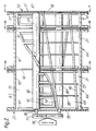
- FIGURE 2 is a detailed diagrammatic view partly in section of a mixing/kneading zone of the apparatus of Figure 1;
- FIGURE 3 is a perspective view of the mixing/kneading zone of Figure 2;
- FIGURES 4a and 4b are cross-sectional views of the apparatus along the lines 4a-4a and 4b-4b respectively of Figure 2;
- FIGURE 5 is a cross-sectional view along line 5-5 of Figure 2.
- The mixing/kneading zone into which the hydrogenated nitrile rubber and extractant liquid are introduced is suitably an apparatus equipped with mixing/kneading elements to which the rubber/liquid mixture is brought into continuously moving contact. The function of the mixing/kneading elements is to ensure continuous intimate mixing of the mixture in the zone, and to ensure that the mixture is in continuously moving contact with the mixing surfaces. It is believed that the mixing generates new rubber surfaces which assist with mass transfer of residue from the rubber to the extractant liquid. There is preferably no dead-space within the mixing/kneading zone.
- Preferably, the apparatus constituting the mixing/kneading zone is in the form of a stationary drum, equipped with rotary mixing/kneading elements arranged to wipe continuously against the interior of the boundary walls as they rotate and perform their mixing/kneading function. The boundary walls and/or the mixing/kneading elements may be heated. In this way the rotary mixing/kneading elements serve to clean the mixing zone walls as they mix and knead.
- These mixing/kneading elements can be paddles, arms, bars, discs, disc segments, pins or combination thereof. These elements are preferably mounted on at least one rotatable shaft within the housing. The use of two shafts is particularly preferred and such shafts may be either co-rotating or counter-rotating during operation and the mixing/kneading elements on the shafts may intermesh or be non-intermeshing during operation. The shaft or shafts may also reciprocate as well as rotate.
- Also in the preferred embodiment, a further set of rotary elements is provided, to move relative to the rotary mixing/kneading elements, and arranged to wipe against the mixing/kneading elements as they rotate and thereby clean the surfaces of the mixing/kneading elements, and the rotary shaft on which they are mounted, as the mixing and kneading proceeds. Such an apparatus is available on the commercial market, for example that known as the AP CONTI, available from List A.G., of Pratteln, Switzerland.
- Preferably, the mixing/kneading zone is divided into sub-zones. This can be effected using weirs or baffles mounted on the housing or by using discs on the shaft or shafts. Also preferred is to have liquid removal means in at least one of the sub-zones. This liquid removal means is located in the lower half of the housing and is preferably provided with means to keep the liquid removal means clear of rubber.
- In practice, the mixing/kneading zone is maintained from about one quarter to about three quarters full of mixture to allow sufficient mixing/kneading space within the mixing/kneading zone for efficient residue removal. This zone can be operated at any suitable pressure, i.e. atmospheric, below atmospheric or above atmospheric, within the tolerance limits of the chosen apparatus. The temperature is maintained below the boiling point of the extractant liquid.
- In one preferred embodiment of the present invention, the rubber discharged from the mixing/kneading zone is supplied to a devolatilizing extruder thereby yielding rubber containing essentially no extractant liquid and which is suitable, after cooling, for packaging.
- The operation of the residue removal process will now be described with reference to Figure 1.
- Hydrogenated nitrile rubber is introduced in a continuous manner, into the mixing/kneading apparatus 30 through the
inlet 40, near theforward end 33. In one embodiment of the invention, extractant liquid is added co-currently throughinlet port 46. The rubber/extractant mixture is mixed and kneaded in the apparatus 30. The temperature of the mixing/kneading zone is slightly below the boiling point of the extractant liquid. When the rubber and extractant enter the apparatus 30, they contact the moving internal surfaces of the mixing zone (such as mixingshaft 80 and cleaningshaft 82, illustrated in Figure 2). - The moving internal surfaces of the apparatus 30 mix and knead the mixture, which is transported towards the
downstream end 34. The extractant liquid is removed atdrain 101, and the rubber is discharged through theextruder 62. Thisextruder 62 is provided with ajacket 64 through which heat transfer medium can flow. - The extractant liquid contains residue which has been removed from the rubber.
- In this preferred embodiment, the rubber which is discharged from the
extruder 62 is ready for final finishing (which may include devolatilization, drying and packaging). - In the continuous process described above, the hydrogenated nitrile rubber (HNBR) is continuously added at 40, and is withdrawn from the
extruder 62 at a similar rate. - It will be apparent that the process may be operated with the extractant liquid being added counter-currently (rather than co-currently, as described above). It will also be apparent that the process could be completed batch-wise, using a mixing/kneading apparatus which is designed for batch use.
- The mixing/kneading apparatus 30 will now be described in more detail with reference to Figures 1 to 5. The apparatus has an internal mixing/kneading zone and is shown in Figure 2 as consisting of three interconnected, commmercially-available
AP CONTI modules 66 similar to the apparatus described in U.S. Patent 3,689,035. All the modules are not identical: they may be equipped with vent ports, drain openings and the like. However, all the modules are of otherwise similar configuration. From three to ten ofsuch modules 66 can be interconnected to form the mixing/kneading apparatus. Thesemodules 66 each have ahousing 67 with a "Figure 8"-shaped cross-section (Figure 4a). One portion of the cross-section (Figure 3) is themain housing portion 68 and the other portion is theauxiliary housing portion 70. Thehousing 67 as a whole is provided (Figure 2) with an outer jacket 72, for heating and cooling purposes. The jacket is suitably designed for handling pressurized fluids up to about 12 bar (atmospheres) at temperatures up to about 350°C. - The modules are interconnected via
spacer plates Spacer plate 74 is simply a metal gasket, of the same size and periphery as the ends of the modules it interconnects. It allows for free flow and communication of materials contained in the mixer, between one module and the next.Spacer plate 76 is a metal gasket equipped with a weir plate extending part way up from the bottom periphery and having a straight horizontal upper edge, with appropriate indentation to accommodate the shafts of the mixing/kneading apparatus, so as to provide a weir between adjacent modules, whereby hold-up and thus residence time of material in a given module can be controlled. The height of the upper edge of thespacer plate 76 may be adjusted for this purpose. - The
upstream end 33 and the downstream end 34 (Figure 1) of the apparatus are each provided with "Figure 8"-shaped flanged covers 75 and 75′ (Figure 2). At theupstream end 33 of the apparatus, there is provided atransmission 77 and a drive motor 78 capable of providing variable speed rotation to each shaft. Each module has twohollow shafts first mixing shaft 80 being located in themain housing portion 68 and the other, cleaningshaft 82 being parallel to the mixingshaft 80 and located in theauxiliary housing portion 70. At the inlet end of the apparatus, packing rings 86 are located between theshafts flanged cover 75. At the outlet end of the apparatus,shafts bearings 87. - As best shown in Figure 3, mounted on the mixing
shaft 80 are axially spaced, radially extending, disk-shapedhollow segments 88 arranged in four circumferentially spaced sets, each set extending helically down theshaft 80, only two of which are shown in Figure 3 for clarity purposes. Each set ofsegments 88 is connected together along the leading periphery by kneadingbars 90 which extend along a helical line from one end of theshaft 80 to the other. These kneading bars contact the inner surface of themain housing portion 68. - The cleaning
shaft 82 has one set of helically arranged, radially extendingarms 92 with adjacent pairs of thesearms 92 being interconnected by cleaningbars 94 to provide a hurdle-type arrangement. These cleaning bars 94 contact the inner surface of theauxiliary housing portion 70. The helical angle of thearms 92 is greater than that of the mixing shaft kneading bars 90 and is chosen so that thearms 92 of the cleaningshaft 82 mesh with and clean the sides of the disk-shapedhollow segments 88 of the mixingshaft 80 upon rotation of the twoshafts bars 90 and thesurface shaft 80.End wall wipers 97 are optionally provided (Figure 2) at each end of the mixingshaft 80 to wipe the inside surfaces of the flanged covers 75 and 75′Spacer plate 76 as shown in Figure 4b may be wiped with additional wipers which may be provided on the shafts for that purpose. Suitably, the motor and transmission can drive the mixing shaft at 3-20 rpm and the cleaning shaft at 12-80 rpm. The speed ratio of the mixing shaft to the cleaning shaft is preferably essentially constant at from 1:2 to 1:6, most preferably at about 1:4. - At the
downstream end 34 of the apparatus 30, theflanged cover 75′, as can be best seen in Figure 5, is provided with avertical slot 98 extending from apex 99 toapex 100 of the "Figure-8"-shaped cross-section of the housing and with circular apertures forbearings 87 to supportshafts slot 98 provides communication to the downwardly extendingdischarge extruder 62. - Also provided toward the
downstream end 34 of the apparatus 30 is adrain opening 101 indicated in Figures 1, 2 and 4a. This drain opening is suitably covered by a screen to retain rubber. This screen is most suitably made up of tri-rod or iso-rod screen bars, a wire mesh, or a plate with plurality of small holes therein. - The
discharge extruder 62 is provided with a variable speed drive (not shown) so that suitably the screw of the extruder can be driven at speeds from 10-200 rpm. - It will be noted that the apparatus 30 of the preferred embodiment described above is an apparatus provided with vents, drains, etc. Material is moved downstream therein, not by the rotation and disposition of the mixing elements, but is gently pushed by the kneading bars 90 and 94, with positive discharge, out of
exit slot 98 intoextruder 62. The apparatus 30 is in no sense an extruder, because the mixing/kneading elements are not capable of compressing the rubber for the apparatus to act as an extruder. - The process will be further described with respect to the following, non-limiting examples which were carried out using either a continuous process or a batch process.
- A hydrogenated nitrile rubber was prepared with a rhodium-based catalyst and a triphenyl phosphine based co-catalyst. Analysis of this rubber showed it to contain 116 ppm Rh and 1.46 weight per cent triphenyl phosphine.
- The rubber was introduced into an A.P. Conti machine operated in a continuous manner. The machine was operated at atmospheric pressure, after heating it to about 60°C and setting the main rotor speed set at 6.5 rpm and the cleaning rotor speed set at 26 rpm.
- The rubber feed rate was about 25 Kg per hour. Methanol, added counter-currently at a rate of 30 litres per hour, was used as the extractant fluid.
- Rubber was collected from the discharge end and subjected to analysis. The rhodium content was determined to be reduced to 86 ppm and the triphenyl phosphine concentration was found to be 1.18 weight per cent. A sample of the extractant fluid was also analyzed, and found to contain 15 ppm Rh and 0.04 weight per cent triphenyl phosphine.
- Rubber which was treated in the manner described in Example 1 was re-introduced into the same A.P. Conti machine, operating under the same temperature and speeds of rotation.
- Thus, once-extracted rubber was added to the machine in a continuous process, at a rate of about 32 Kg per hour.
- The extractant fluid used in this example was thiourea-in-methanol (0.1 weight/volume per cent), and was added at a rate of 30 litres/hour.
- Three samples of hydrogenated nitrile rubber were analyzed and found to contain 66, 71 and 69 ppm of Rh, respectively, indicating a further reduction in the amount of Rh contained in the rubber.
- This example illustrates a batch extraction process.
- 2.4 Kg of hydrogenated nitrile rubber containing 1.2% weight per cent residual solvent (chlorobenzene) was added to a batch kneading/mixing machine, manufactured by List. 2.4 Kg of methanol were also added to the machine. The machine was operated at about 60° C and atmospheric pressure, well below boiling conditions for methanol.
- After 60 minutes, 1.6 Kg of the extractant fluid was drained. A sample of the rubber was analyzed and found to contain about 0.8 weight per cent chlorobenzene.
- 1.6 Kg of fresh methanol was then added to the machine, and the process was repeated at about 60°C for a further 60 minutes. The extractant fluid was then drained.
- A sample of the rubber was analyzed and found to contain 0.4 weight per cent chlorobenzene.
Claims (7)
- A solvent-free process to extract residue from hydrogenated nitrile rubber, wherein said residue may contain residual catalyst, cocatalyst or solvent from the hydrogenation process, said solvent being present only as a minor part, said process comprising:(i) adding residue-containing hydrogenated nitrile rubber to a mixing/kneading zone which comprises a housing with at least one mixing shaft therein, said mixing shaft having mixing elements attached thereto and being rotatably mounted within said housing;(ii) adding from 20 to 500 parts by weight, per 100 parts by weight of said rubber, of an extractant liquid to said mixing/kneading zone, at a temperature below the boiling point of said extractant liquid;(iii) subjecting said hydrogenated nitrile rubber and said extractant liquid to a period of continuous mixing/kneading within said mixing/kneading zone;(iv) repeatedly mechanically cleaning the mixing/kneading zone;(v) discharging said hydrogenated nitrile rubber from said mixing/kneading zone;(vi) discharging said extractant liquid from said mixing/kneading zone, and separating said liquid from said rubber;wherein said extractant liquid is not a good solvent for said rubber but is miscible with at least part of said residue, characterized in that said process is completed without the addition of a solvent for said hydrogenated nitrile rubber.
- The process of Claim 1 which further comprises passing said hydrogenated nitrile rubber through an extruder, after discharging it from said mixing/kneading zone.
- The process of Claim 1 when completed in a continuous manner.
- The process of Claim 1 wherein said extractant comprises from 20 to 200 parts by weight methanol per 100 parts by weight of said hydrogenated nitrile rubber.
- The process of Claim 1 wherein said extractant is perchloroethylene.
- The process of Claim 4 wherein said extractant further contains thiourea.
- The process of Claim 6 when completed at a temperature of between 50 and 60°C and atmospheric pressure.
Applications Claiming Priority (2)
| Application Number | Priority Date | Filing Date | Title |
|---|---|---|---|
| US07/205,813 US4857632A (en) | 1988-06-13 | 1988-06-13 | Residue removal process |
| US205813 | 1988-06-13 |
Publications (3)
| Publication Number | Publication Date |
|---|---|
| EP0346778A2 EP0346778A2 (en) | 1989-12-20 |
| EP0346778A3 EP0346778A3 (en) | 1991-08-28 |
| EP0346778B1 true EP0346778B1 (en) | 1994-09-07 |
Family
ID=22763738
Family Applications (1)
| Application Number | Title | Priority Date | Filing Date |
|---|---|---|---|
| EP89110508A Expired - Lifetime EP0346778B1 (en) | 1988-06-13 | 1989-06-10 | Residue removal process |
Country Status (4)
| Country | Link |
|---|---|
| US (1) | US4857632A (en) |
| EP (1) | EP0346778B1 (en) |
| CA (1) | CA1335023C (en) |
| DE (1) | DE68918000T2 (en) |
Families Citing this family (9)
| Publication number | Priority date | Publication date | Assignee | Title |
|---|---|---|---|---|
| DE4118884A1 (en) * | 1991-06-07 | 1992-12-10 | List Ag | MIXING kneader |
| DE4326807A1 (en) * | 1993-08-10 | 1995-02-16 | Bayer Ag | Completely self-cleaning mixer |
| DE4339628C2 (en) * | 1993-11-20 | 2003-04-10 | Ismar Maschinen Gmbh | kneading |
| EP0715881B1 (en) * | 1994-12-05 | 1998-02-25 | Bayer Ag | Fully self-cleaning mixer/reactor |
| EP0715882B1 (en) * | 1994-12-05 | 1998-02-25 | Bayer Ag | Self-cleaning reactor/mixer for high viscosity mixtures containing solids |
| US6043299A (en) | 1996-10-31 | 2000-03-28 | Shell Oil Company | Process for the extraction of material from multi-phase systems |
| CN1120850C (en) * | 2000-03-10 | 2003-09-10 | 南帝化学工业股份有限公司 | Process for removing hydrocatalyst from unsaturated copolymer |
| DE10321875A1 (en) * | 2003-05-15 | 2004-12-02 | Bayer Ag | HXNBR rubber as crosslinking agent |
| WO2017222514A1 (en) * | 2016-06-22 | 2017-12-28 | Zeon Chemicals, Lp | Process for recovery of residual hydrogenation catalyst from hydrogenated nitrile rubber solution |
Family Cites Families (4)
| Publication number | Priority date | Publication date | Assignee | Title |
|---|---|---|---|---|
| US2786047A (en) * | 1952-02-11 | 1957-03-19 | Phillips Petroleum Co | Process for removing nickel catalyst from hydrogenated polybutadiene |
| US3531448A (en) * | 1968-11-06 | 1970-09-29 | Phillips Petroleum Co | Process for removal of hydrogenation catalyst from hyrogenated polymers |
| DE2539132A1 (en) * | 1975-09-03 | 1977-03-17 | Bayer Ag | HYDROGENATION OF POLYMERS |
| US4909898A (en) * | 1986-10-01 | 1990-03-20 | Polysar Limited | Polymer recovery from solution |
-
1988
- 1988-06-13 US US07/205,813 patent/US4857632A/en not_active Expired - Lifetime
-
1989
- 1989-06-02 CA CA000601674A patent/CA1335023C/en not_active Expired - Fee Related
- 1989-06-10 DE DE68918000T patent/DE68918000T2/en not_active Expired - Fee Related
- 1989-06-10 EP EP89110508A patent/EP0346778B1/en not_active Expired - Lifetime
Also Published As
| Publication number | Publication date |
|---|---|
| EP0346778A2 (en) | 1989-12-20 |
| CA1335023C (en) | 1995-03-28 |
| DE68918000D1 (en) | 1994-10-13 |
| EP0346778A3 (en) | 1991-08-28 |
| US4857632A (en) | 1989-08-15 |
| DE68918000T2 (en) | 1995-01-19 |
Similar Documents
| Publication | Publication Date | Title |
|---|---|---|
| EP0262594B1 (en) | Polymer recovery from solution | |
| EP0346778B1 (en) | Residue removal process | |
| CN1272096C (en) | Continuous stirring device and continuous polycondensing method for polymer resin | |
| US4776703A (en) | Continuous treatment apparatus for viscous material | |
| DE2349106A1 (en) | MIXING KNEDE WITH COUNTER SHOVELS | |
| EP1824587B1 (en) | Reactor for the treatment of highly viscous plastic melts | |
| DE69814643T2 (en) | METHOD AND DEVICE FOR PRODUCING POLYCARBONATES | |
| KR20000023714A (en) | Polymer recovery | |
| EP2328677B1 (en) | Device for carrying out mechanical, chemical and/or thermal processes | |
| EP0185527A2 (en) | Methods and apparatus for mixing liquid with viscous material | |
| EP0002362B1 (en) | Screw vent for devolatilizer | |
| AU747258B2 (en) | Method and apparatus for producing olive oil without pressing the stones | |
| KR100934207B1 (en) | Method and apparatus for extracting material from liquid or solid dispersions | |
| EP0187005A2 (en) | Methods and apparatus for purifying liquid materials | |
| CH460718A (en) | Additional device on a mixing and kneading device for the further treatment of soft pasty products | |
| CN112642179B (en) | Breakdown of emulsion fire fighting equipment is condensed in butadiene acrylonitrile rubber production | |
| JPH05277303A (en) | Solid extractor | |
| US4390506A (en) | Apparatus for trouble-free and continuous charging of extractors with extraction feedstock to be treated and with extractant or solvent | |
| CH426735A (en) | Combined mixing and homogenizing machine | |
| JPS59126411A (en) | After-treatment of styrene polymerization product | |
| CN110997275A (en) | Extruder system with pressure regulating device | |
| CN114939388A (en) | Reaction kettle with multi-kettle-body inner cavity structure | |
| CN220656404U (en) | Low molecular weight remover | |
| CN216395327U (en) | But self-heating draws jar | |
| CN219481885U (en) | Separation and purification device for extracting plant components |
Legal Events
| Date | Code | Title | Description |
|---|---|---|---|
| PUAI | Public reference made under article 153(3) epc to a published international application that has entered the european phase |
Free format text: ORIGINAL CODE: 0009012 |
|
| AK | Designated contracting states |
Kind code of ref document: A2 Designated state(s): BE DE FR GB IT NL |
|
| 17P | Request for examination filed |
Effective date: 19901205 |
|
| PUAL | Search report despatched |
Free format text: ORIGINAL CODE: 0009013 |
|
| AK | Designated contracting states |
Kind code of ref document: A3 Designated state(s): BE DE FR GB IT NL |
|
| RHK1 | Main classification (correction) |
Ipc: C08C 3/02 |
|
| 17Q | First examination report despatched |
Effective date: 19930816 |
|
| GRAA | (expected) grant |
Free format text: ORIGINAL CODE: 0009210 |
|
| AK | Designated contracting states |
Kind code of ref document: B1 Designated state(s): BE DE FR GB IT NL |
|
| PG25 | Lapsed in a contracting state [announced via postgrant information from national office to epo] |
Ref country code: NL Effective date: 19940907 Ref country code: BE Effective date: 19940907 |
|
| ITF | It: translation for a ep patent filed |
Owner name: JACOBACCI CASETTA & PERANI S.P.A. |
|
| REF | Corresponds to: |
Ref document number: 68918000 Country of ref document: DE Date of ref document: 19941013 |
|
| ET | Fr: translation filed | ||
| NLV1 | Nl: lapsed or annulled due to failure to fulfill the requirements of art. 29p and 29m of the patents act | ||
| PLBE | No opposition filed within time limit |
Free format text: ORIGINAL CODE: 0009261 |
|
| STAA | Information on the status of an ep patent application or granted ep patent |
Free format text: STATUS: NO OPPOSITION FILED WITHIN TIME LIMIT |
|
| 26N | No opposition filed | ||
| REG | Reference to a national code |
Ref country code: GB Ref legal event code: IF02 |
|
| PGFP | Annual fee paid to national office [announced via postgrant information from national office to epo] |
Ref country code: FR Payment date: 20040524 Year of fee payment: 16 |
|
| PGFP | Annual fee paid to national office [announced via postgrant information from national office to epo] |
Ref country code: GB Payment date: 20040609 Year of fee payment: 16 |
|
| PGFP | Annual fee paid to national office [announced via postgrant information from national office to epo] |
Ref country code: DE Payment date: 20040618 Year of fee payment: 16 |
|
| PG25 | Lapsed in a contracting state [announced via postgrant information from national office to epo] |
Ref country code: IT Free format text: LAPSE BECAUSE OF NON-PAYMENT OF DUE FEES;WARNING: LAPSES OF ITALIAN PATENTS WITH EFFECTIVE DATE BEFORE 2007 MAY HAVE OCCURRED AT ANY TIME BEFORE 2007. THE CORRECT EFFECTIVE DATE MAY BE DIFFERENT FROM THE ONE RECORDED. Effective date: 20050610 Ref country code: GB Free format text: LAPSE BECAUSE OF NON-PAYMENT OF DUE FEES Effective date: 20050610 |
|
| PG25 | Lapsed in a contracting state [announced via postgrant information from national office to epo] |
Ref country code: DE Free format text: LAPSE BECAUSE OF NON-PAYMENT OF DUE FEES Effective date: 20060103 |
|
| PG25 | Lapsed in a contracting state [announced via postgrant information from national office to epo] |
Ref country code: FR Free format text: LAPSE BECAUSE OF NON-PAYMENT OF DUE FEES Effective date: 20060228 |
|
| GBPC | Gb: european patent ceased through non-payment of renewal fee |
Effective date: 20050610 |
|
| REG | Reference to a national code |
Ref country code: FR Ref legal event code: ST Effective date: 20060228 |