EP0346628B1 - Elastic saddle support for a two-wheeled vehicle mounted on the frame in the direction of the rear wheel axle - Google Patents
Elastic saddle support for a two-wheeled vehicle mounted on the frame in the direction of the rear wheel axle Download PDFInfo
- Publication number
- EP0346628B1 EP0346628B1 EP89108809A EP89108809A EP0346628B1 EP 0346628 B1 EP0346628 B1 EP 0346628B1 EP 89108809 A EP89108809 A EP 89108809A EP 89108809 A EP89108809 A EP 89108809A EP 0346628 B1 EP0346628 B1 EP 0346628B1
- Authority
- EP
- European Patent Office
- Prior art keywords
- guide tube
- spring
- seat pillar
- frame
- bicycle seat
- Prior art date
- Legal status (The legal status is an assumption and is not a legal conclusion. Google has not performed a legal analysis and makes no representation as to the accuracy of the status listed.)
- Expired - Lifetime
Links
- 238000006073 displacement reaction Methods 0.000 claims 1
- 229910000831 Steel Inorganic materials 0.000 abstract description 6
- 239000010959 steel Substances 0.000 abstract description 6
- 239000000725 suspension Substances 0.000 description 9
- 230000000750 progressive effect Effects 0.000 description 4
- 239000000314 lubricant Substances 0.000 description 2
- 230000002265 prevention Effects 0.000 description 2
- TVEXGJYMHHTVKP-UHFFFAOYSA-N 6-oxabicyclo[3.2.1]oct-3-en-7-one Chemical compound C1C2C(=O)OC1C=CC2 TVEXGJYMHHTVKP-UHFFFAOYSA-N 0.000 description 1
- 239000006096 absorbing agent Substances 0.000 description 1
- 238000013016 damping Methods 0.000 description 1
- 230000000694 effects Effects 0.000 description 1
- 210000001035 gastrointestinal tract Anatomy 0.000 description 1
- 230000002452 interceptive effect Effects 0.000 description 1
- 238000009420 retrofitting Methods 0.000 description 1
- 230000035939 shock Effects 0.000 description 1
Images

Classifications
-
- B—PERFORMING OPERATIONS; TRANSPORTING
- B62—LAND VEHICLES FOR TRAVELLING OTHERWISE THAN ON RAILS
- B62J—CYCLE SADDLES OR SEATS; AUXILIARY DEVICES OR ACCESSORIES SPECIALLY ADAPTED TO CYCLES AND NOT OTHERWISE PROVIDED FOR, e.g. ARTICLE CARRIERS OR CYCLE PROTECTORS
- B62J1/00—Saddles or other seats for cycles; Arrangement thereof; Component parts
- B62J1/02—Saddles resiliently mounted on the frame; Equipment therefor, e.g. springs
- B62J1/06—Saddles capable of parallel motion up and down
-
- B—PERFORMING OPERATIONS; TRANSPORTING
- B62—LAND VEHICLES FOR TRAVELLING OTHERWISE THAN ON RAILS
- B62K—CYCLES; CYCLE FRAMES; CYCLE STEERING DEVICES; RIDER-OPERATED TERMINAL CONTROLS SPECIALLY ADAPTED FOR CYCLES; CYCLE AXLE SUSPENSIONS; CYCLE SIDE-CARS, FORECARS, OR THE LIKE
- B62K19/00—Cycle frames
- B62K19/30—Frame parts shaped to receive other cycle parts or accessories
- B62K19/36—Frame parts shaped to receive other cycle parts or accessories for attaching saddle pillars, e.g. adjustable during ride
Definitions
- the invention relates to a device according to the first part of claim 1 (FR-A-66 6858) for the resilient suspension of the two-wheeler saddle on the vehicle frame, so that the bumps caused by uneven floors cannot be passed on to the driver.
- the resilient two-wheel seat post is essentially built from two tubes that are guided into one another by a lubricant.
- the outer tube, guide tube, is attached to the frame via the fastening part, outside, and the inner tube is either a specially developed gas spring, which rests with its working shaft on the support part of the guide tube, or a tube, which is at its lower end, via the adjusting screw, rests on a steel spring.
- Both springs are adjusted to the weight of the moving person by mechanical action on the adjustment screw provided, in the gas spring by a volume limiting piston that changes the volume and the gas pressure and in the coil spring by adjusting the counter pressure of the coil spring on the seat post.
- the resilient seat post is fixed to the frame via the fastening part (7), rigidly or in an angular position, via a pipe section or via the existing rigid seat post.
- the rigid attachment via a pipe section offers the advantage of a low-cost version for the original equipment manufacturer and the adjustable angle mounting on the existing rigid seat post, the advantage of a low-cost version for retrofitting.
- the springy two-wheel seat post is constructed in its designs from simple individual parts, so that it can be produced either together with the two-wheelers or separately, so that it can either be fitted as initial equipment or subsequently.
- the invention offers the advantage that it can be retrofitted, for example, to any known two-wheeled frame design by simple handling and can therefore be used over a wide area on many different two-wheeled vehicles.
- the new development creates the possibility for the production of a simple, inexpensive and durable, resilient two-wheel seat post that is interesting for the two-wheeler parts and accessories market.
Landscapes
- Engineering & Computer Science (AREA)
- Mechanical Engineering (AREA)
- Fluid-Damping Devices (AREA)
- Tires In General (AREA)
- Vehicle Body Suspensions (AREA)
- Axle Suspensions And Sidecars For Cycles (AREA)
- Vibration Prevention Devices (AREA)
- Automatic Cycles, And Cycles In General (AREA)
Abstract
Description
Die Erfindung bezieht sich auf eine Vorrichtung gemäß dem ersten Teil des Patentanspruchs 1 (FR-A-66 6858) zur federnden Aufhängung des Zweirad Sattels am Fahrzeugrahmen, so daß die durch Bodenunebenheiten wirkenden Stöße nicht an die fahrende Person weitergeleitet werden können.The invention relates to a device according to the first part of claim 1 (FR-A-66 6858) for the resilient suspension of the two-wheeler saddle on the vehicle frame, so that the bumps caused by uneven floors cannot be passed on to the driver.
Eine Vielzahl von Entwürfen federnder Zweirad Sattelstützen sind seit ca. 1920 bekannt ohne daß es bis heute gelungen ist, eine federnde Zweirad Sattelstütze zu konstruieren, die ihren Anforderungen gut und kostengünstig entspricht, drel Problempunkte waren bis heute nicht zufriedenstellend gelöst:
- 1. DIE BEFESTIGUNG,
welche bis jetzt MEISTENS direkt IM Rahmen an Stelle der festen Sattelstütze, mit einem durch den Rahmen vorgegebenen ungünstigen Befestigungswinkel, erfolgte. Diese Winkelstellung ist, bezüglich der bei den Bodenstößen wirkenden Kräften, für gutes und leichtes Gleiten der federnden Teile, bei ihren Bewegungen ungünstig.
Auch eine VERTIKALE Befestigung, wie z.B. die Patentschrift 666,858, ist der Befestigung IN RICHTUNG AUF DIE HINTERACHSE nicht gleichzusetzen. - 2. DER FEDERUNGSKOMFORT.
Die bisher immer wieder benutzten, im Inneren der federnden Sattelstützen eingebauten Schraubenfedern, hatten wegen ihrer vorgeschriebenen Baumaße, auf das jeweilige Gewicht der fahrenden Person vorgespannt, eine zu progressive Kennlinie und boten dadurch einen unbefriedigenden Federungskomfort, auch die Patentschrift 666,858, ist mit zu progressiven Federn ausgestattet und ohne die Möglickeit einer Gewichtseinstellung. - 3. DIE VERHINDERUNG DER VERDREHUNG,
bei der es bis jetzt bei KEINER Sattelstütze gelungen war, eine spielfreie Verhinderung der Verdrehung zu schaffen, ohne dabei den Federungsweg und Federkomfort durch störendes Reiben der Teile miteinander zu behindern.
- 1. THE FASTENING,
which up to now MOSTLY took place directly in the frame instead of the fixed seat post, with an unfavorable fastening angle given by the frame. This angular position is unfavorable for their movements with respect to the forces acting on the ground impacts for good and easy sliding of the resilient parts.
A VERTICAL fastening, such as the patent specification 666,858, is not the same as fastening TOWARDS THE REAR AXLE. - 2. THE SUSPENSION COMFORT.
The coil springs used so far, installed inside the resilient seat posts, had a too progressive characteristic due to their prescribed dimensions, preloaded on the respective weight of the driving person, and thus offered unsatisfactory suspension comfort, also the patent specification 666,858 is with progressive springs equipped and without the possibility of a weight adjustment. - 3. PREVENTING THE TWIST,
in which up until now it was not possible to prevent the seat post from twisting without backlash, without hindering the suspension travel and spring comfort by interfering rubbing of the parts.
Der Erfindung liegt die Aufgabe zugrunde, die zuvor genannten Schwächen und Nachteile der bekannten federnden Zweirad Sattelstützen aufzuheben und die Möglichkeit zu schaffen, auf einfache, günstige und dauerhaft-sichere Weise eine gute Federung für die fahrende Person zu ermöglichen. Diese Aufgaben der federnden Zweirad Sattelstütze, die über eine Feder gegenüber dem Rahmen abgefedert und mit Mitteln zur Verhinderung einer Verdrehung versehen ist, sind erfindungsgemäß gemäß dem Patentanspruch 1 und Vorzugsweise wie folgt gelöst :
- 1.) Die Befestigung,
die im allgemeinen bekannte, wegen zu großer Reibung der federnden Teile, ungünstige Befestigungungslage (Befestigung direkt im Rahmen), wird durch ein Befestigungsteil (7) gelöst.
Die federnde Sattelstütze ist über dem Befestigungsteil (7) außerhalb des Rahmens, IN GLEICHER LINIE MIT DEN WIRKENDEN KRÄFTEN der Bodenstöße von dem Hinterrad, so befestigt, daß sie bei ihrer Federungsbewegung die kleinstmögliche Reibung zwischen den federnden Teilen aufweist und dadurch den bestmöglichen Federungskomfort bietet. - 2.) Der Federungskomfort,
ist entweder durch die speziell entwickelte Gasfeder oder durch eine koaxial über die Sattelstütze montierte Stahlfeder, mit großem Durchmesser, beide mit einer flachen Kennlinie, so gelöst, daß erstmals eine sehr gute Federung, unabhängig von verschiedenen Gewichten der Benutzer, in seiner vollen vorgesehenen Länge möglich ist.
Die hier beschriebene Gasfeder ist so gebaut, daß sie eine progressivere Kennlinie aufweist, als die ganz flachen Kennlinien der allgemein bekannten Gasfedern. Dies wird durch die Reduzierung des Gasvolumens auf ein Minimum erreicht, so daß bei dem vorgesehenen Arbeitsweg der Gasdruck im Innern der Feder vergleichsweise schnell ansteigt und die Gasfeder dadurch die erwünschte Kennlinie bietet. - 3.) Die Verhinderung der Verdrehung,
ist durch eine speziell entwickelte Verdrehungssperre so gelöst, daß die Verdrehungskräfte auf die gegeneinander federnden Teile, über die dafür vorgesehenen Elemente, weit entfernt von der Achse der federnden Teile weggeleitet werden.
Die Verdrehungskräfte werden dann an den äußeren Enden dieser Teile in dafür vorgesehenen Drehpunkten mit Verbindungsteilen aufgefangen und über diese zu einem gemeinsamen Drehschnittpunkt weitergeleitet.
In diesem Drehschnittpunkt heben sich die Verdrehungskräfte gegenseitig auf, so daß OHNE Reibungseffekt eine spielfreie Drehverhinderung geschaffen worden ist.
- 1.) The attachment,
the generally known, due to excessive friction of the resilient parts, unfavorable mounting position (mounting directly in the frame) is solved by a mounting part (7).
The resilient seat post is attached above the fastening part (7) outside the frame, IN THE SAME LINE WITH THE EFFECTIVE forces of the rear wheel, in such a way that it has the smallest possible friction between the resilient parts during its suspension movement and thus offers the best possible suspension comfort. - 2.) The suspension comfort,
is solved either by the specially developed gas spring or by a coaxially mounted steel spring with a large diameter, both with a flat characteristic, both with a flat characteristic, so that for the first time a very good suspension, regardless of different weights of the users, is possible in its full intended length is.
The gas spring described here is built so that it has a more progressive characteristic than the very flat characteristics of the well-known gas springs. This is achieved by reducing the gas volume to a minimum, so that the gas pressure inside the spring rises comparatively quickly in the intended working path and the gas spring thereby offers the desired characteristic. - 3.) The prevention of twisting,
is solved by a specially developed torsion lock so that the torsional forces on the mutually resilient parts are directed away from the axis of the resilient parts via the elements provided.
The torsional forces are then absorbed at the outer ends of these parts in designated pivot points with connecting parts and passed on to a common pivot intersection.
At this point of rotation, the torsional forces cancel each other out, so that a backlash-free rotation prevention has been created WITHOUT the friction effect.
Die federnde Zweirad Sattelstütze ist im wesentlichen aus zwei über ein Gleitmittel ineinander geführten Rohren gebaut.The resilient two-wheel seat post is essentially built from two tubes that are guided into one another by a lubricant.
Das äußere Rohr, Führungsrohr, ist über das Befestigungsteil, außen, am Rahmen befestigt und das innere Rohr ist entweder eine speziell hierfür entwickelte Gasfeder, die mit ihrer Arbeitswelle auf dem Auflageteil des Führungsrohrs aufliegt, oder ein Rohr, das an seinem unteren Ende, über der Verstellschraube, auf einer Stahlfeder aufliegt.The outer tube, guide tube, is attached to the frame via the fastening part, outside, and the inner tube is either a specially developed gas spring, which rests with its working shaft on the support part of the guide tube, or a tube, which is at its lower end, via the adjusting screw, rests on a steel spring.
Beide Federn werden dem Gewicht der fahrenden Person durch mechanische Einwirkung an der dafür vorgesehenen Verstellschraube angepaßt, bei der Gasfeder durch einen Volumenbegrenzungskolben, der das Volumen und den Gasdruck verändert und bei der Schraubenfeder durch Anpassen des Gegendrucks der Schraubenfeder auf die Sattelstütze.Both springs are adjusted to the weight of the moving person by mechanical action on the adjustment screw provided, in the gas spring by a volume limiting piston that changes the volume and the gas pressure and in the coil spring by adjusting the counter pressure of the coil spring on the seat post.
Die federnde Sattelstütze ist, über das Befestigungsteil (7), starr oder in Winkellage einstellbar, über ein Rohrstück oder über die vorhandene starre Sattelstütze, am Rahmen befestigt.The resilient seat post is fixed to the frame via the fastening part (7), rigidly or in an angular position, via a pipe section or via the existing rigid seat post.
Die starre Befestigung über ein Rohrstück bietet den Vorteil, eine günstige Ausführung für die Erstausstatter und die in Winkellage einstellbare Befestigung, an der vorhandenen starren Sattelstütze, den Vorteil einer günstigen Ausführung für die nachträgliche Ausstattung.The rigid attachment via a pipe section offers the advantage of a low-cost version for the original equipment manufacturer and the adjustable angle mounting on the existing rigid seat post, the advantage of a low-cost version for retrofitting.
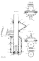
- Fig. 1Fig. 1
- Schnitt der kompletten federnden Zweirad Sattelstütze, Ausführung mit Gasfeder, inkl. dem im Neigungswinkel verstellbaren Befestigungsteils für die Montage auf eine vorhandene einfache Sattelstütze - laut Anspruch 5Section of the complete resilient two-wheel seat post, version with gas spring, incl. The fastening part that is adjustable in the angle of inclination for mounting on an existing simple seat post - according to claim 5
- Fig. 2Fig. 2
- Vorderansicht der verwendeten Verdrehungssperre, aus dieser Zeichnung sind alle einzelnen Teile der Verdrehungssperre in ihrer Arbeitslage und ihrer Abhängigkeit voneinander zu ersehen.Front view of the anti-rotation lock used, from this drawing all individual parts of the anti-rotation lock can be seen in their working position and their interdependence.
- Fig. 3 u. Fig. 4Fig. 3 u. Fig. 4
-
Schnitte der Befestigungsteile - laut Anspruch 6Cuts of the fastening parts - according to
claim 6 - Fig. 5Fig. 5
- Schnitt der kompletten federnden Sattelstütze, Ausführung mit Stahlfeder, inkl. dem im Neigungswinkel verstellbaren Befestigungsteils für die Montage auf eine vorhandene einfache Sattelstütze - laut Anspruch 5Section of the complete resilient seat post, version with steel spring, incl. The fastening part adjustable in inclination for mounting on an existing simple seat post - according to claim 5
- Fig. 6 u. Fig. 7Fig. 6 u. Fig. 7
- Schnitte der verwendeten Verdrehungssperre, inklusiv dem im Neigungswinkel verstellbaren Befestigungsteils auseinandergeklappt.Cuts of the twist lock used, including the fastening part that can be adjusted in the angle of inclination, unfolded.
- 11
- Führungsrohr der federnden SattelstützeGuide tube of the resilient seat post
- 22nd
- Boden des Führungsrohrs bei GasfedernBottom of the guide tube for gas springs
- 33rd
- Arbeitswelle der GasfederWorking wave of the gas spring
- 44th
- EndaufpralldämpfungsfederEnd impact damping spring
- 55
- Gleitmittel zwischen¬ Sattelstütze und dem FührungsrohrLubricant between seat post and the guide tube
- 66
- Sattelstütze-Innenrohr = Stahlrohr oder GasfederSeat post inner tube = steel tube or gas spring
- 77
- eine Hälfte des winkelverstellbaren Befestigungsteilsone half of the angle-adjustable fastening part
- 88th
- eine Hälfte der Befestigung der Verdrehungssperreone half of the attachment of the anti-rotation lock
- 99
- Verstellschraube zur GewichtsanpaßungAdjustment screw for weight adjustment
- 1010th
- Bekannte Gasfederkolben mit RichtungsventilenKnown gas spring pistons with directional valves
- 1111
- Dichtungs- und Führungspaket der Welle (3)Seal and guide package of the shaft (3)
- 1212
- Volumenbegrenzungskolben, welcher das Volumen der Gasfeder und damit ihren Innendruck verändertVolume limiting piston, which changes the volume of the gas spring and thus its internal pressure
- 1313
- Gewindeteil, der die Verstellschraube führtThreaded part that guides the adjusting screw
- 1414
- Stahlfeder der SattelstützeSteel spring of the seat post
- 1515
- vorhandene starre Sattelstützeexisting rigid seat post
- 1616
- Verbindungsteile der VerdrehungssperreConnection parts of the anti-rotation lock
- 1717th
- Drehgelenke der VerdrehungssperreSwivel of the anti-rotation lock
- 1818th
- Bodenteil der Sattelstütze für VerstellschraubeBottom part of the seat post for adjusting screw
- 1919th
- Rohrstück zur Rahmenbefestigung der SattelstützePipe piece for fastening the seat post to the frame
- 2020th
- Gummiring als EndaufpralldämpfungRubber ring as a shock absorber
Die federnde Zweirad Sattelstütze ist in ihren Ausführungen aus einfachen Einzelteilen konstruiert, dadurch kann ihre Produktion entweder zusammen mit den Zweirädern, oder auch separat erfolgen, so daß sie entweder als Erstausstattung oder auch nachträglich angebracht werden kann.The springy two-wheel seat post is constructed in its designs from simple individual parts, so that it can be produced either together with the two-wheelers or separately, so that it can either be fitted as initial equipment or subsequently.
Die Erfindung bietet den Vorteil, daß sie zum Beispiel nachträglich durch einfache Handhabung an jede bekannte Zweiradrahmenausführung anzubringen ist und somit sehr breitflächig an vielen verschiedenen Zweirädern Einsatzmöglichkeiten finden kann.The invention offers the advantage that it can be retrofitted, for example, to any known two-wheeled frame design by simple handling and can therefore be used over a wide area on many different two-wheeled vehicles.
Die Neuentwicklung schafft die Möglichkeit für die Produktion einer einfachen, günstigen und dauerhaften, für den Zweiradteile und Zubehörmarkt interessanten, federnden Zweirad Sattelstütze.The new development creates the possibility for the production of a simple, inexpensive and durable, resilient two-wheel seat post that is interesting for the two-wheeler parts and accessories market.
Claims (6)
- Cushioned bicycle seat pillar (6), whose guide tube (1) is mounted on the outside of the rear frame spar by means of a fixture and inclined TOWARD THE REAR WHEEL AXLE, and which is capable of axial displacement within the guide tube (1) against the pressure of the spring (14) and thus cushioned against the frame, CHARACTERIZED IN THAT the means of preventing rotation of the bicycle seat pillar (6) relative to the guide tube (1) comprise two similar, mirror-inverted forks (16) connected by a hinge.
- Cushioned bicycle seat pillar according to Claim 1,
CHARACTERIZED IN THAT the spring (14) is a special gas spring. - Cushioned bicycle seat pillar according to Claim 1,
CHARACTERIZED IN THAT the spring (14) is a helical spring, coaxially wound around the guide tube (1), and fastened at one end to the guide tube (1), the other end being fastened to the seat pillar (6). - Cushioned bicycle seat pillar according to any of Claims 1 to 3,
CHARACTERIZED IN THAT the counterforce of the spring (14) is adjustable. - Cushioned bicycle seat pillar according to any of Claims 1 to 4,
CHARACTERIZED IN THAT the guide tube (1) is mounted to the frame by means of a mounting fixture (7) fastened to the existing rigid seat pillar (15) at the point at which the saddle is usually mounted. - Cushioned bicycle seat pillar according to any of Claims 1 to 4,
CHARACTERIZED IN THAT the guide tube (1) is connected, either rigidly or with angular adjustment capability, by means of a mounting fixture (7) to a piece of tube (19) which is inserted and clamped into the upper orifice of the rear frame spar instead of the usual saddle pillar.
Priority Applications (1)
| Application Number | Priority Date | Filing Date | Title |
|---|---|---|---|
| AT89108809T ATE83720T1 (en) | 1988-05-19 | 1989-05-17 | SUSPENSION SEATPOST MOUNTED ON THE FRAME FACING THE REAR WHEEL AXLE. |
Applications Claiming Priority (2)
| Application Number | Priority Date | Filing Date | Title |
|---|---|---|---|
| DE8806577U DE8806577U1 (en) | 1988-05-19 | 1988-05-19 | Suspension bicycle seat post |
| DE8806577U | 1988-05-19 |
Publications (2)
| Publication Number | Publication Date |
|---|---|
| EP0346628A1 EP0346628A1 (en) | 1989-12-20 |
| EP0346628B1 true EP0346628B1 (en) | 1992-12-23 |
Family
ID=6824215
Family Applications (1)
| Application Number | Title | Priority Date | Filing Date |
|---|---|---|---|
| EP89108809A Expired - Lifetime EP0346628B1 (en) | 1988-05-19 | 1989-05-17 | Elastic saddle support for a two-wheeled vehicle mounted on the frame in the direction of the rear wheel axle |
Country Status (5)
| Country | Link |
|---|---|
| EP (1) | EP0346628B1 (en) |
| AT (1) | ATE83720T1 (en) |
| AU (1) | AU3681289A (en) |
| DE (2) | DE8806577U1 (en) |
| WO (1) | WO1989011413A1 (en) |
Cited By (1)
| Publication number | Priority date | Publication date | Assignee | Title |
|---|---|---|---|---|
| EP0827899A2 (en) | 1996-09-06 | 1998-03-11 | Tino Simic | Spring saddle support for a twowheeled vehicle |
Families Citing this family (4)
| Publication number | Priority date | Publication date | Assignee | Title |
|---|---|---|---|---|
| DE4031273A1 (en) * | 1990-10-04 | 1991-05-16 | Gerhard Froehlich | Shock absorbing saddle for bicycle - has two springs and second guide tube to prevent rotation of saddle |
| FR2693424B1 (en) * | 1992-07-10 | 1994-10-14 | Bernard Duruisseau | Shock absorber replacing the seat post of a cycle. |
| CA2172569A1 (en) * | 1996-03-25 | 1997-09-26 | William Michael Newman | High efficiency bicycle seat suspension |
| WO1999011510A1 (en) * | 1997-09-04 | 1999-03-11 | William Michael Newman | High efficiency bicycle seat suspension |
Family Cites Families (5)
| Publication number | Priority date | Publication date | Assignee | Title |
|---|---|---|---|---|
| US1442643A (en) * | 1920-09-22 | 1923-01-16 | Brooks J B & Co Ltd | Cycle seat |
| FR666858A (en) * | 1928-04-11 | 1929-10-07 | Shock absorber | |
| FR657016A (en) * | 1928-07-05 | 1929-05-16 | Saddle damper device for cycles and motorcycles | |
| FR1020035A (en) * | 1950-06-12 | 1953-01-30 | Elastic suspension saddle with variable flexibility, with vertical telescopic tubes | |
| DE8706953U1 (en) * | 1987-05-14 | 1988-09-15 | Simic, Tino, 4150 Krefeld | Anti-twist lock for spring-loaded bicycle handlebars or seat posts |
-
1988
- 1988-05-19 DE DE8806577U patent/DE8806577U1/en not_active Expired
-
1989
- 1989-05-17 DE DE8989108809T patent/DE58903083D1/en not_active Expired - Fee Related
- 1989-05-17 EP EP89108809A patent/EP0346628B1/en not_active Expired - Lifetime
- 1989-05-17 AU AU36812/89A patent/AU3681289A/en not_active Abandoned
- 1989-05-17 WO PCT/EP1989/000537 patent/WO1989011413A1/en not_active Ceased
- 1989-05-17 AT AT89108809T patent/ATE83720T1/en not_active IP Right Cessation
Cited By (2)
| Publication number | Priority date | Publication date | Assignee | Title |
|---|---|---|---|---|
| EP0827899A2 (en) | 1996-09-06 | 1998-03-11 | Tino Simic | Spring saddle support for a twowheeled vehicle |
| EP0827899A3 (en) * | 1996-09-06 | 1998-04-01 | Tino Simic | Spring saddle support for a twowheeled vehicle |
Also Published As
| Publication number | Publication date |
|---|---|
| EP0346628A1 (en) | 1989-12-20 |
| DE58903083D1 (en) | 1993-02-04 |
| AU3681289A (en) | 1989-12-12 |
| DE8806577U1 (en) | 1989-09-14 |
| ATE83720T1 (en) | 1993-01-15 |
| WO1989011413A1 (en) | 1989-11-30 |
Similar Documents
| Publication | Publication Date | Title |
|---|---|---|
| EP0958998B1 (en) | Guide for the front wheel of a motorcycle | |
| EP0493773A2 (en) | Bicycle with sprung suspension | |
| DE102010025694A1 (en) | Bicycle assembly with reinforcement | |
| DE830162C (en) | Suspension for vehicles, especially motor vehicles, in which the wheels of an axle are individually suspended from the frame on the upper and lower wishbones | |
| EP1238900A2 (en) | Bicycle frame | |
| EP0346628B1 (en) | Elastic saddle support for a two-wheeled vehicle mounted on the frame in the direction of the rear wheel axle | |
| DE3913528C2 (en) | Resilient suspension of a motor vehicle wheel | |
| EP1964695B1 (en) | Pneumatic spring and damping unit with operating element | |
| DE4116814C1 (en) | Motorcycle handlebar with two vibratory arms - de4119125 coupled by sprung and damped housing with two separate chambers, each with two absorbers | |
| DE102008004089B4 (en) | Coil spring for a chassis | |
| DE2507071A1 (en) | INDEPENDENT WHEEL SUSPENSION FOR MOTOR VEHICLES | |
| DE19501848B4 (en) | Wheel suspension for the steered front wheels of a motor vehicle | |
| DE2134995A1 (en) | Vehicle suspension | |
| DE1219340B (en) | Spring suspension of steered wheels, especially for motor vehicles | |
| DE3827760A1 (en) | WHEELED SPRING ARRANGEMENT OF A MOTOR VEHICLE | |
| DE29909138U1 (en) | Suspension, swiveling seat post with cushioning | |
| DE4001143C1 (en) | Independent suspension on vehicle - has spring bearing on lower link and damper connected to upper link | |
| DE1555404A1 (en) | Wheel suspension system for motor vehicles | |
| DE2932699A1 (en) | Stabilised front wheel suspension - has stabiliser between front dampers on pivot mountings | |
| DE906052C (en) | Adjustment device for telescopic suspension, especially of motorcycles and. like | |
| DE102022101463B4 (en) | Device for providing a restoring torque for a two-wheel steering mechanism | |
| DE3816836A1 (en) | Rear-wheel suspension for motorcycles | |
| EP0827899B1 (en) | Spring saddle support for a twowheeled vehicle | |
| DE7801356U1 (en) | ADJUSTABLE SPRING AND CUSHIONING SEAT POST | |
| DE19633819A1 (en) | Wheel suspension for motor vehicle with stabiliser |
Legal Events
| Date | Code | Title | Description |
|---|---|---|---|
| PUAI | Public reference made under article 153(3) epc to a published international application that has entered the european phase |
Free format text: ORIGINAL CODE: 0009012 |
|
| AK | Designated contracting states |
Kind code of ref document: A1 Designated state(s): AT BE CH DE ES FR GB GR IT LI LU NL SE |
|
| 17P | Request for examination filed |
Effective date: 19900510 |
|
| 17Q | First examination report despatched |
Effective date: 19910819 |
|
| GRAA | (expected) grant |
Free format text: ORIGINAL CODE: 0009210 |
|
| AK | Designated contracting states |
Kind code of ref document: B1 Designated state(s): AT BE CH DE ES FR GB GR IT LI LU NL SE |
|
| PG25 | Lapsed in a contracting state [announced via postgrant information from national office to epo] |
Ref country code: SE Effective date: 19921223 Ref country code: GR Free format text: LAPSE BECAUSE OF FAILURE TO SUBMIT A TRANSLATION OF THE DESCRIPTION OR TO PAY THE FEE WITHIN THE PRESCRIBED TIME-LIMIT Effective date: 19921223 Ref country code: ES Free format text: THE PATENT HAS BEEN ANNULLED BY A DECISION OF A NATIONAL AUTHORITY Effective date: 19921223 Ref country code: BE Effective date: 19921223 |
|
| REF | Corresponds to: |
Ref document number: 83720 Country of ref document: AT Date of ref document: 19930115 Kind code of ref document: T |
|
| REF | Corresponds to: |
Ref document number: 58903083 Country of ref document: DE Date of ref document: 19930204 |
|
| ITF | It: translation for a ep patent filed | ||
| ET | Fr: translation filed | ||
| GBT | Gb: translation of ep patent filed (gb section 77(6)(a)/1977) |
Effective date: 19930312 |
|
| PG25 | Lapsed in a contracting state [announced via postgrant information from national office to epo] |
Ref country code: LU Free format text: LAPSE BECAUSE OF NON-PAYMENT OF DUE FEES Effective date: 19930531 Ref country code: LI Effective date: 19930531 Ref country code: CH Effective date: 19930531 |
|
| PLBE | No opposition filed within time limit |
Free format text: ORIGINAL CODE: 0009261 |
|
| STAA | Information on the status of an ep patent application or granted ep patent |
Free format text: STATUS: NO OPPOSITION FILED WITHIN TIME LIMIT |
|
| 26N | No opposition filed | ||
| REG | Reference to a national code |
Ref country code: CH Ref legal event code: PL |
|
| PGFP | Annual fee paid to national office [announced via postgrant information from national office to epo] |
Ref country code: FR Payment date: 19970328 Year of fee payment: 9 |
|
| PGFP | Annual fee paid to national office [announced via postgrant information from national office to epo] |
Ref country code: DE Payment date: 19970421 Year of fee payment: 9 |
|
| PGFP | Annual fee paid to national office [announced via postgrant information from national office to epo] |
Ref country code: GB Payment date: 19970507 Year of fee payment: 9 |
|
| PGFP | Annual fee paid to national office [announced via postgrant information from national office to epo] |
Ref country code: AT Payment date: 19970526 Year of fee payment: 9 |
|
| PGFP | Annual fee paid to national office [announced via postgrant information from national office to epo] |
Ref country code: NL Payment date: 19970530 Year of fee payment: 9 |
|
| PG25 | Lapsed in a contracting state [announced via postgrant information from national office to epo] |
Ref country code: GB Free format text: LAPSE BECAUSE OF NON-PAYMENT OF DUE FEES Effective date: 19980517 Ref country code: AT Free format text: LAPSE BECAUSE OF NON-PAYMENT OF DUE FEES Effective date: 19980517 |
|
| PG25 | Lapsed in a contracting state [announced via postgrant information from national office to epo] |
Ref country code: FR Free format text: LAPSE BECAUSE OF NON-PAYMENT OF DUE FEES Effective date: 19980531 |
|
| PG25 | Lapsed in a contracting state [announced via postgrant information from national office to epo] |
Ref country code: NL Free format text: LAPSE BECAUSE OF NON-PAYMENT OF DUE FEES Effective date: 19981201 |
|
| GBPC | Gb: european patent ceased through non-payment of renewal fee |
Effective date: 19980517 |
|
| NLV4 | Nl: lapsed or anulled due to non-payment of the annual fee |
Effective date: 19981201 |
|
| PG25 | Lapsed in a contracting state [announced via postgrant information from national office to epo] |
Ref country code: DE Free format text: LAPSE BECAUSE OF NON-PAYMENT OF DUE FEES Effective date: 19990302 |
|
| REG | Reference to a national code |
Ref country code: FR Ref legal event code: ST |
|
| PG25 | Lapsed in a contracting state [announced via postgrant information from national office to epo] |
Ref country code: IT Free format text: LAPSE BECAUSE OF NON-PAYMENT OF DUE FEES Effective date: 20050517 |