EP0346534B1 - Appareil d'étirage de fils et procédé - Google Patents
Appareil d'étirage de fils et procédé Download PDFInfo
- Publication number
- EP0346534B1 EP0346534B1 EP19880305397 EP88305397A EP0346534B1 EP 0346534 B1 EP0346534 B1 EP 0346534B1 EP 19880305397 EP19880305397 EP 19880305397 EP 88305397 A EP88305397 A EP 88305397A EP 0346534 B1 EP0346534 B1 EP 0346534B1
- Authority
- EP
- European Patent Office
- Prior art keywords
- wire
- wire drawing
- block
- dies
- section
- Prior art date
- Legal status (The legal status is an assumption and is not a legal conclusion. Google has not performed a legal analysis and makes no representation as to the accuracy of the status listed.)
- Expired - Lifetime
Links
Images

Classifications
-
- B—PERFORMING OPERATIONS; TRANSPORTING
- B21—MECHANICAL METAL-WORKING WITHOUT ESSENTIALLY REMOVING MATERIAL; PUNCHING METAL
- B21C—MANUFACTURE OF METAL SHEETS, WIRE, RODS, TUBES, PROFILES OR LIKE SEMI-MANUFACTURED PRODUCTS OTHERWISE THAN BY ROLLING; AUXILIARY OPERATIONS USED IN CONNECTION WITH METAL-WORKING WITHOUT ESSENTIALLY REMOVING MATERIAL
- B21C1/00—Manufacture of metal sheets, wire, rods, tubes or like semi-manufactured products by drawing
- B21C1/02—Drawing metal wire or like flexible metallic material by drawing machines or apparatus in which the drawing action is effected by drums
- B21C1/12—Regulating or controlling speed of drawing drums, e.g. to influence tension; Drives; Stop or relief mechanisms
-
- B—PERFORMING OPERATIONS; TRANSPORTING
- B21—MECHANICAL METAL-WORKING WITHOUT ESSENTIALLY REMOVING MATERIAL; PUNCHING METAL
- B21C—MANUFACTURE OF METAL SHEETS, WIRE, RODS, TUBES, PROFILES OR LIKE SEMI-MANUFACTURED PRODUCTS OTHERWISE THAN BY ROLLING; AUXILIARY OPERATIONS USED IN CONNECTION WITH METAL-WORKING WITHOUT ESSENTIALLY REMOVING MATERIAL
- B21C1/00—Manufacture of metal sheets, wire, rods, tubes or like semi-manufactured products by drawing
- B21C1/02—Drawing metal wire or like flexible metallic material by drawing machines or apparatus in which the drawing action is effected by drums
- B21C1/04—Drawing metal wire or like flexible metallic material by drawing machines or apparatus in which the drawing action is effected by drums with two or more dies operating in series
Definitions
- the present invention generally relates to machines for drawing metal wire, for example, those used to manufacture wires to be bunched into conductors for flexible insulated cords, and more particularly to a wire drawing apparatus and method which facilitate changeovers to provide different wire reductions.
- Wire drawing is an operation which is carried out in several passes, i.e. by passing the wire through a series of dies, the diameter of each of which is smaller than that of the preceding die.
- the wire is drawn through the dies by drawing capstans commonly referred to as “drawing blocks,” the peripheral speeds of which increase progressively as the wire moves forward.
- wire drawing machines In one system of wire drawing which is used at present and is known as "wet wire drawing," the dies and, in some cases, the drawing blocks, are sprayed or immersed in a lubricating solution.
- Wire drawing machines can be divided into two classes, namely, in the single wire class which is more widely used at present, and the multi-wire class, the use of which is on the increase.
- Wire drawing machines can also be divided into two different groups depending on the types of wire drawing blocks that are used.
- a first group of machines called "cone-type” wire drawing machines are characterized by drawing blocks of different diameters which are securely mounted on one and the same shaft to form a stepped cylinder or cone.
- the wire is looped around two sets of cones carried by a pair of spaced and substantially parallel shafts, and the dies are located in a die holder positioned in the path of the runs of wire between the two sets of cones.
- Wire drawing machines may comprise several pairs of cones, for example, two. This type of wire drawing machine offer the advantage of being very compact.
- the wire having the greatest diameter passes over the block having the smallest diameter, (i.e. the block providing the lowest speed). For certain types of applications this might not be satisfactory.
- a second group of wire drawing machines have independent drawing blocks each mounted on a separate shaft. These machines are usually called “tandem" machines.
- the number of blocks is usually equal to the number of dies, with each die being upstream of its associated drawing block.
- the blocks which in most applications have the same diameter, are driven at different speeds and the surface speed matches as closely as possible the difference in elongation between each die.
- the blocks may be positioned in many different arrangements, such as in-line, in a circle, along a spiral, etc.
- the wire can be strung along these blocks more easily than in the cone machines, but the drives are more complicated since a large number of blocks must all be driven at different speeds.
- Multi-wire machines include both cone types and tandem type machines. Multi-wire machines with many configurations of cone and tandem blocks have been used in the art and they allow the drawing of several wires at the same time. At present eight wire machines are the most common.
- All wire drawing machines are designed in such a way as to provide a pre-set difference in surface speed between successive blocks and this speed difference becomes a fixed parameter of the machine.
- the differences in surface speeds dictate the maximum reduction in area and the relative elongation of the wire from one block to the following one.
- the "reduction parameters" between successive drawing blocks can be arbitrarily assigned, the reduction parameters will establish the reductions in cross-sectional areas of the wires and, therefore, the percentages elongation of the wire between successive stages. This will dictate the speeds of the various drawing blocks, bearing in mind that while the physical dimensions of the wire between different drawing blocks changes, the total amount of material remains the same.
- the "reduction" parameters are not arbitrarily selected but are fixed by conventions in order to provide standard wire sizes.
- the standard wire sizes are also a function of the specific metals used to form the wires.
- a standard has been established in the United States designated the B & S American Wire Gauge (AWG).
- the wire gauges are assigned designations of 6/0 for the largest diameter wire to 56 for the finest wire.
- the ratio of the diameter of each gauge wire is approximately 0.89 to the diameter of the next or adjacent gauge wire.
- DE-A-3 106 830 describes a wire drawing machine having a plurality of drawing blocks mounted in tandem, and each associated with a drawing die. If the smallest possible diameter of wire is required, all of the dies are used, the dies being arranged so that each die is of smaller diameter than the preceding die. When a larger diameter of wire is required, one or more dies are removed from the downstream end of the string, and their blocks allowed to run idle; the speed of the final capstan is adjusted accordingly.
- the invention provides, in one aspect thereof, wire drawing apparatus comprising:
- the invention also extends to a wire drawing method, and therefore provides in an alternative aspect a method comprising the steps of:
- the first section or part of the machine may include cone sections, tandem blocks or both, and is arranged to reduce an incoming elongate metallic material to an intermediate wire of predetermined diameter which is greater than the diameters of a predetermined range of desired output production wire sizes.
- the speed of the drive for the first section can be changed to advance the output intermediate wire at adjustable preset speeds that can be selected depending on the mode of operation of the system.
- the second part of the machine or section reduces the incoming wire of predetermined diameter from the first drawing section to a wire having a desired output diameter within said predetermined range.
- the second section includes any desired number of tandem blocks, normally 4 or more, and a final capstan drawing block all coupled to each other, and a plurality of interchangeable drawing dies each respectively positioned upstream of an associated drawing blocks.
- the drawing blocks and dies are diemensioned to provide predetermined changes in elongation and velocity following each reduction by a die. With four tandem blocks and a final capstan, the new configuration provides for great flexibility since the machine can produce five different diameters without requiring restringing by just eliminating one or more of the four dies comprised in the second tandem block section.
- a second drive is provided for driving the second wire drawing section at a selected second speed to provide the desired production of the output of the final capstan drawing block. If n tandem drawing blocks are provided in addition to the final capstan drawing block, n + 1 different wire sizes within said predetermined range of desired output production wire sizes can be obtained by eliminating n i dies upstream of the final Capstan drawing block, wherein n i is less than or equal n.
- the remaining dies are advanced n i positions downstream and the speed of the first drive is selected to provide a first speed which corresponds at least to the velocity of the wire prior to the first reduction in the first die upsteam of the n i + 1 drawing block,
- the present invention can be applied to all slip wet wire drawing machines and does not require modification of established wire drawing practices, including slip characteristics.
- the speed of the last capstan of the first section is much slower than the final capstan, it is possible to increase the speed of the first section to match the speed of the capstan upstream of the first active capstan (the first capstan that pulls the wire through a die). This can be done for all the n + 1 sizes (5 sizes where 4 tandem drawing blocks are provided) without restringing of the first section, and there is no need to use expensive and high maintenance clutches or couplings to disengage any of the unused shafts.
- first and second sections can be varied in design to provide the best mix of diameters that each user wishes to obtain.
- the second section could be designed with six tandem capstan instead of five, thus allowing the user to produce seven diameters without restringing.
- this configuration allows the production of wire sizes that fall between the diameters of the standard dies by just changing the dies in the second tandem section and adjusting the relative speed between the two sections to match the non-standard diameters that one wants to produce.
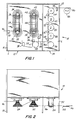
- FIGS. 1 and 2 there is schematically shown one presently preferred embodiment of a drawing machine in accordance with the present invention generally designated by the reference numeral 10.
- the drawing machine 10 may be of the single wire class, as opposed to the multi-wire class machine to be more fully described in connection with FIGS. 5 and 6, although the machine 10 can be adapted to process two wires simultaneously.
- the drawing machine 10 has a first part or section 12 serially followed by a second part or section 14.
- An incoming elongate metallic material, such as a heavy gauge wire W i enters the first section 12 through the housing 16 and is reduced by a series of drawing blocks and associated dies to an intermediate wire diameter W m which is greater than the diameters of a predetermined range of desired output production wire sizes.
- the intermediate diameter wire W m is advanced through a further series of reduction stages wherein the intermediate wire W m is reduced to a final output wire W0.
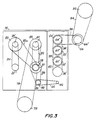
- the incoming elongate metallic material W i passes through an input die 18 and associated first cone drawing block 20 mounted for rotation with a shaft 22.
- a second cone drawing block 24 is mounted for rotation with a shaft 26, a die holder 28 being interposed between the drawing blocks 20 and 24 which support a plurality of dies positioned in the paths of movement of the wires extending between successive steps of the cone drawing blocks as shown and is well known to those skilled in the art.
- the wire Upon leaving the last step of the drawing block 24, the wire passes over idler rollers 30 and 32 and extends through a die 34 prior to engagement with a third cone drawing block 36 mounted for rotation with shaft 38.
- a fourth cone-type drawing block 40 mounted for rotation with shaft 42 cooperates with the third drawing block 36 and with a die holder 44 in a similar manner as described in connection with the first two drawing blocks 20 and 24.
- the wire After leaving the last step of the fourth drawing block 40, the wire passes through a die 46 and engages its associated drawing block 48.
- all of the drawing blocks and dies mentioned thus far are all enclosed within the housing 16 of the first part or section 12 of the drawing apparatus.
- the wire Prior to leaving the housing 16, the wire extends through a die 50 and thereupon exits the housing 16 and engages associated drawing block 56 arranged within the housing 52 of the second section 14.
- drawing block 56 Arranged downstream of the drawing block 56 are a series of tandem, serially arranged drawing blocks 58, 60, 62, 64 and a final capstan drawing block 66, each provided with associated dies 68, 70, 72, 74 and 76, respectively.
- the drawing sections 12, 14 are "wet wire drawing” sections, and, therefore, they may be filled with a lubricating solution L or alternately, the dies and/or drawing blocks can be sprayed or otherwise lubricated.
- the dies 18 and 76 are advantageously sealing dies which seal the input and outlet openings of the containers 16 and 52 to prevent or minimize the escape of lubricating fluid therefrom.
- drawing blocks and dies in the first section 12 is not critical for purposes of the present invention. Numerous known combinations of cone, tandem and/or combinations of such drawing blocks and dies can be used to reduce the incoming elongate metallic material W i to an intermediate or desired wire W m having a desired diameter or gauge. As will be discussed more fully in connection with FIGS. 4A-E, if the range of B & S wire gauges desire to be produced on the drawing apparatus includes AWG gauges 26-30, the intermediate wire W m , in the embodiment shown, may be selected at AWG 25 wire gauge.
- the wire gauge of the intermediate wire W m is selected at 12 AWG, the range of wire gauges which can be produced by the drawing apparatus includes wire gauges 13-17.
- the drawing arrangements used in arriving at the intermediate wire gauge W m is not critical and is dictated by considerations of economy, size and other factors well understood by those skilled in the art.
- the output die 76 is the last die prior to the final capstan drawing blocks 66 and is disposed within the housing 52 of the second section 14.
- a drive motor pulley 78 for the first section 12 is shown together with the various linkages, belts and gearings 79, 82, 82a, 84, 86 and 90, which engage associated pulleys, gears and sprockets 22′, 26′, 38′, 42′, 78, 81, 83, 86, 88, 89 and 92 as shown.
- This arrangement drives the first section drawing blocks, including the drawing blocks 20, 24, 36, 40, 48 and 56 to advance the intermediate wire W m at a selected first linear speed.
- the remainder of the drawing blocks 58, 60, 62, 64 and 66 are all linked to, directly or indirectly, and controlled by a second section drive motor pulley 92 which can, for example, utilize a drive belt 94 to engage a pulley 66′ mounted on the shaft carrying the final capstan 66, with belts 96, 98, 100 and 102 being used to couple the successive drawing blocks via pulleys of appropriate diameters 66'', 64′, 64'', 62′, 62'', 60′, 60'' and 58′.
- the motor pulley 92 of the second section can be advantageously adjusted at a selectible second speed to provide the desired production at the output of the final capstan drawing block 66.
- the speed of the motor pulley 78 of the first section can advantageously be modified to establish the required linear velocity of the intermediate wire W m needed to provide the necessary reductions with all the drawing blocks and dies in place as shown in FIG. 1 or with one or more drawing blocks and dies removed as will be described in connection with FIGS. 4-4E.
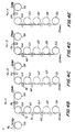
- each successive reduction by a die requires an increase in linear velocity at the output of that die of about 26%.
- the intermediate wire W m entering the first die 68 in the second section 14 is a 25 gauge wire.
- the normalized linear velocity of the wire W m in FIG. 4 is equal to 1
- the normalized velocity of the output wire W0 is approximately 3.18.
- the output of the dies 68, 70, 72, 74 and 76 are wire gauges 26, 27, 28, 29 and 30, respectively.
- the die preceding and associated with the final capstan drawing block 66 is removed or eliminated, and the remaining drawing blocks are advanced one position downstream so that the dies 68, 70, 72 and 74 are now respectively associated with the drawing blocks 60, 62, 64 and 66.
- the speed of the first section motor pulley 78 is increased to increase the rotational velocities of the various linked or coupled elements so that the last drawing block 56 which forms part of the first section is increased by a factor of 1.26 or by 26%.
- the 25 gauge wire can be advanced to the first die 68 at a sufficiently high speed to compensate for the elimination of the one reduction and thereby maintain the linear velocity of the output wire W o .
- the wire gauge can be modified within a given range to select anyone of a number of different wire gauges, in the example, wire gauges 26-30.
- the selection of wire gauges within a predetermined or desired range is achieved by increasing the velocity of the rotating components in the first section which is initially low as compared to the output velocities of the second stage. The increase in velocity of the first section does not, therefore, present a problem insofar as the capabilities of the bearings and rotating elements are concerned.
- FIGS. 5 and 6 a multi-wire system is shown which operates, and all essential features, in the way described above in connection with the single wire system.
- the only difference, of course, is that multiple wires are guided simultaneously and adjacently to each other on drawing blocks 48a, 56a, 58a, 60a, 62a, 64a and 66a, each being reduced by its own associated dies 50a, 68a, 70a, 72a, 74a and 76a.
- the modifications to the previously described embodiment would be well within the capabilities of those skilled in the art.
- the increases in efficiency in the use of the wire drawing apparatus and method of the present invention can best be illustrated by a few simple calculations. For example, on a typical wire drawing machine set up to produce a single 30 AWG gauge wire, it presently takes approximately 30 minutes to restring the machine to produce a different gauge wire. Assuming an eight hour working day and assuming two wire size changes or restringings of the machine in one day, the down time of the machine is 60 minutes out of an eight hour day. With the subject apparatus and method, the same change in wire size can be effected within approximately five minutes. There is, therefore, a saving of 50 minutes per day of down time, and this represents approximately a 12% increase in efficiency in the running time of the machine.
Landscapes
- Engineering & Computer Science (AREA)
- Mechanical Engineering (AREA)
- Metal Extraction Processes (AREA)
- Winding, Rewinding, Material Storage Devices (AREA)
Claims (17)
- Un appareil à tréfiler comprenant:(a) une première section de tréfilage pour réduire une matière métallique allongée d'arrivée en un fil intermédiaire de diamètre prédéterminé qui est supérieur aux diamètres d'une gamme prédéterminée de tailles de sortie de fils de production désirés;(b) un premier moyen d'entraînement pour entraîner ladite première section de tréfilage et faire avancer le fil intermédiaire à un premier régime linéaire sélectionnable;(c) une deuxième section de tréfilage pour recevoir et réduire sélectivement le fil d'un diamètre prédéterminé de ladite première section de tréfilage, enun fil ayant un diamètre de sortie désiré dans ladite gamme prédéterminée, ladite deuxième section de tréfilage englobant des tambours tandems de tréfilerie n et un tambour-cabestan de tréfilerie final tous accouplés les uns aux autres, et plusieurs filières n + 1 interchangeables et chacunes respectivement positionnées en amont d'un tambour de tréfilerie associé, lesdits tambours de tréfilerie et filières étant dimensionnés de manière à fournir des changements prédéterminés d'allongement et de vitesse suite à chaque réduction effectuée par une filière;
et(d) un deuxième moyen d'entraînement pour entraîner ladite deuxième section de tréfilage à un deuxième régime sélectionnable pour donner le rendement désiré à la sortie dudit tambour-cabestan de tréfilerie final, le régime du deuxième moyen d'entraînement étant réglable indépendamment du premier moyen d'entraînement, moyen par lequel les différentes tailles de fil n + 1 à l'intérieur de ladite gamme prédéterminée de tailles de sortie de fils de production désirés, peuvent être obtenues en éliminant des filières ni en amont dudit tambour-cabestan de tréfilerie final, en faisant avancer les filières restantes de ni positions en aval et en réglant ledit premier moyen d'entraînement pour qu'il fournisse un premier régime qui correspond à la vitesse du fil préalablement à la première réduction dans la première filière en amont du tambour de tréfilerie ni + 1, où ni ≦ n. - Un appareil à tréfiler comme défini dans la première revendication, dans lequel ladite première section de tréfilage comprend au moins une paire de tambours de tréfilerie coniques.
- Un appareil à tréfiler comme défini dans la deuxième revendication, dans lequel deux paires de tambours de tréfilerie coniques sont fournis.
- Un appareil à tréfiler comme défini dans la deuxième revendication, comprenant en plus au moins un tambour tandem de tréfilerie.
- Un appareil à tréfiler comme défini dans la quatrième revendication, dans lequel deux tambours tandems de tréfilerie sont fournis.
- Un appareil à tréfiler comme défini dans la quatrième revendication, dans lequel ledit tambour tandem de tréfilerie au minimum, est positionné en aval de ladite paire de tambours de tréfilerie coniques au minimum.
- Un appareil à tréfiler comme défini dans la première revendication, dans lequel ladite première section de tréfilage comprend au moins un tambour tandem de tréfilerie.
- Un appareil à tréfiler comme défini dans la première revendication, dans lequel n=4.
- Un appareil à tréfiler comme défini dans la première revendication, dans lequel ladite première section de tréfilage comprend un tambour de tréfilerie technique entraîné par ledit premier moyen d'entraînement et disposé sur ladite deuxième section de tréfilage.
- Un appareil à tréfiler comme défini dans la neuvième revendication, dans lequel ledit tambour de tréfilerie final est un tambour tandem de tréfilerie.
- Un appareil à tréfiler comme défini dans la première revendication, dans lequel l'appareil à tréfiler est une machine multifils, et dans lequel lesdites première et deuxième sections de tréfilage comprennent des tambours de tréfilerie et des filières pour traiter simultanément des fils multiples.
- Un appareil à tréfiler comme défini dans la première revendication, dans lequel n=4 et ni=0.
- Un appareil à tréfiler comme défini dans la première revendication, dans lequel 0=4 et ni=1.
- Un appareil à tréfiler comme défini dans la première revendication, dans lequel n=4 et ni=2,
- Un appareil à tréfiler comme défini dans la première revendication, dans lequel n=4 et ni=3.
- Un appareil à tréfiler comme défini dans la première revendication, dans lequel n=4 et ni=4.
- Un appareil à tréfiler comprenant les étapes suivantes:(a) réduction, dans une première section de tréfilage, d'une matière métallique allongée d'arrivée en un fil intermédiaire d'un diamètre prédéterminé qui est supérieur aux diamètres d'une gage prédéterminée de tailles de sortie de fils de production désirés;(b) ladite première section de tréfilage, fait avancez le fil intermédiaire à un premier régime linéaire sélectionnable;(c) réception et réduction sélective, dans une deuxième section de tréfilage, du fil de diamètre prédéterminé de ladite première section de tréfilage, en un fil ayant un diamètre de sortie désiré dans ladite gamme prédéterminée, ladite deuxième section de tréfilage englobant des tambours tandems de tréfilerie et un tambour-cabestan de tréfilerie final tous accouplés les uns aux autres, et plusieurs filières n + 1 interchangeables positionnées en amont d'un tambour de tréfilerie associé, lesdits tambours de tréfilerie et filières étant dimensionnés de manière à fournir des changements prédéterminés d'allongement et de vitesse suite à chaque réduction effectuée par une filière;
et(d) entraînement de ladite deuxième section de tréfilage à un deuxième régime sélectionnable, ledit deuxième régime étant sélectionnable indépendamment dudit premier régime linéaire, afin de donner le rendement désiré à la sortie dudit tambour-cabestan de tréfilerie final, moyen par lequel les différentes tailles de fil n + 1 dans ladite gamme prédéterminée de tailles de sortie de fils de production désirés, peuvent être obtenues en éliminant les filières ni en amont dudit tambour-cabestan de tréfilerie final, en faisant avancer les autres filières de ni positions en aval et en réglant ledit premier moyen d'entraînement pour donner un premier régime qui correspond à la vitesse du fil préalablement à la première réduction dans la première filière en amont du tambour de tréfilerie ni + 1, où ni ≦ n.
Priority Applications (4)
| Application Number | Priority Date | Filing Date | Title |
|---|---|---|---|
| US06/794,079 US4750344A (en) | 1985-11-01 | 1985-11-01 | Wire drawing apparatus and method |
| DE19883853586 DE3853586T2 (de) | 1988-06-13 | 1988-06-13 | Drahtziehvorrichtung und Verfahren. |
| ES88305397T ES2074439T3 (es) | 1988-06-13 | 1988-06-13 | Aparato y metodo de trefilar. |
| EP19880305397 EP0346534B1 (fr) | 1988-06-13 | 1988-06-13 | Appareil d'étirage de fils et procédé |
Applications Claiming Priority (1)
| Application Number | Priority Date | Filing Date | Title |
|---|---|---|---|
| EP19880305397 EP0346534B1 (fr) | 1988-06-13 | 1988-06-13 | Appareil d'étirage de fils et procédé |
Publications (3)
| Publication Number | Publication Date |
|---|---|
| EP0346534A2 EP0346534A2 (fr) | 1989-12-20 |
| EP0346534A3 EP0346534A3 (en) | 1990-07-25 |
| EP0346534B1 true EP0346534B1 (fr) | 1995-04-12 |
Family
ID=8200099
Family Applications (1)
| Application Number | Title | Priority Date | Filing Date |
|---|---|---|---|
| EP19880305397 Expired - Lifetime EP0346534B1 (fr) | 1985-11-01 | 1988-06-13 | Appareil d'étirage de fils et procédé |
Country Status (3)
| Country | Link |
|---|---|
| EP (1) | EP0346534B1 (fr) |
| DE (1) | DE3853586T2 (fr) |
| ES (1) | ES2074439T3 (fr) |
Families Citing this family (3)
| Publication number | Priority date | Publication date | Assignee | Title |
|---|---|---|---|---|
| DE20314589U1 (de) | 2003-09-20 | 2003-11-20 | Jagow + Pfeifer GmbH & Co. KG, 35578 Wetzlar | Drahtziehmaschine |
| JP5282683B2 (ja) * | 2009-07-02 | 2013-09-04 | 住友電装株式会社 | 伸線装置及び素線の製造方法 |
| CN112275815B (zh) * | 2020-09-30 | 2022-06-24 | 乐清志向电磁线有限公司 | 一种电磁线生产的低能耗拉丝工艺及拉丝装置 |
Family Cites Families (2)
| Publication number | Priority date | Publication date | Assignee | Title |
|---|---|---|---|---|
| US3462993A (en) * | 1966-07-29 | 1969-08-26 | Syncro Mach Co | Machine for the drawing of superfine wire |
| DE3106830A1 (de) * | 1981-02-24 | 1982-09-09 | Werner 6349 Hörbach Henrich | Verfahren zum ziehen von draehten sowie maschine zur durchfuehrung des verfahrens |
-
1988
- 1988-06-13 ES ES88305397T patent/ES2074439T3/es not_active Expired - Lifetime
- 1988-06-13 EP EP19880305397 patent/EP0346534B1/fr not_active Expired - Lifetime
- 1988-06-13 DE DE19883853586 patent/DE3853586T2/de not_active Expired - Fee Related
Also Published As
| Publication number | Publication date |
|---|---|
| DE3853586T2 (de) | 1995-11-09 |
| DE3853586D1 (de) | 1995-05-18 |
| ES2074439T3 (es) | 1995-09-16 |
| EP0346534A3 (en) | 1990-07-25 |
| EP0346534A2 (fr) | 1989-12-20 |
Similar Documents
| Publication | Publication Date | Title |
|---|---|---|
| EP0601998B1 (fr) | Appareil pour fabriquer des fils câblés et machine pour fabriquer des fils concentriquement câblés | |
| US2869316A (en) | Twisted conductors and cables and method and apparatus for making the same | |
| US4750344A (en) | Wire drawing apparatus and method | |
| US3373550A (en) | Methods of and apparatus for alternate-reverse twisting of indefinite lengths of strand material | |
| EP0346534B1 (fr) | Appareil d'étirage de fils et procédé | |
| US3842643A (en) | Processing of wires | |
| JPH04258311A (ja) | 伸線方法および伸線機 | |
| WO1989012514A1 (fr) | Appareil et procede de trefilage | |
| DE19809875A1 (de) | Vorrichtung zum Zuführen von Faserbändern an Streckwerken von Spinnereimaschinen, insbesondere von Strecken | |
| US4455817A (en) | Apparatus for the manufacture of a fancy yarn | |
| EP1273426A1 (fr) | Extrudeuse entraínée directement et méthode d'opération d'une telle extrudeuse | |
| CN219292409U (zh) | 一种拉丝机的驱动结构 | |
| US3462993A (en) | Machine for the drawing of superfine wire | |
| US3979940A (en) | Wire drawing machinery | |
| US4882923A (en) | Continuous mill plant for rolling steel plates | |
| US2956102A (en) | Twisted conductors and cables | |
| CA1264154A (fr) | Methode et machine de trefilage | |
| JP3007346B1 (ja) | 紡糸設備の繊維延伸装置 | |
| US3823543A (en) | Method of making spun multi-wire articles | |
| KR900007547B1 (ko) | 고능률 와이어 연선장치 | |
| US3293899A (en) | Methods of extrusion and wiredrawing of metallic products and devices for the practical application of said improved methods | |
| US2902886A (en) | Multiple-wire drawing machine transmission | |
| PL91100B1 (fr) | ||
| GB2058634A (en) | Wire-drawing machine | |
| US4370849A (en) | Stranding device of a stranding machine |
Legal Events
| Date | Code | Title | Description |
|---|---|---|---|
| PUAI | Public reference made under article 153(3) epc to a published international application that has entered the european phase |
Free format text: ORIGINAL CODE: 0009012 |
|
| AK | Designated contracting states |
Kind code of ref document: A2 Designated state(s): DE ES FR GB IT |
|
| PUAL | Search report despatched |
Free format text: ORIGINAL CODE: 0009013 |
|
| AK | Designated contracting states |
Kind code of ref document: A3 Designated state(s): DE ES FR GB IT |
|
| 17P | Request for examination filed |
Effective date: 19901129 |
|
| 17Q | First examination report despatched |
Effective date: 19911112 |
|
| GRAA | (expected) grant |
Free format text: ORIGINAL CODE: 0009210 |
|
| AK | Designated contracting states |
Kind code of ref document: B1 Designated state(s): DE ES FR GB IT |
|
| REF | Corresponds to: |
Ref document number: 3853586 Country of ref document: DE Date of ref document: 19950518 |
|
| ITF | It: translation for a ep patent filed | ||
| ET | Fr: translation filed | ||
| REG | Reference to a national code |
Ref country code: ES Ref legal event code: FG2A Ref document number: 2074439 Country of ref document: ES Kind code of ref document: T3 |
|
| PLBE | No opposition filed within time limit |
Free format text: ORIGINAL CODE: 0009261 |
|
| STAA | Information on the status of an ep patent application or granted ep patent |
Free format text: STATUS: NO OPPOSITION FILED WITHIN TIME LIMIT |
|
| 26N | No opposition filed | ||
| PGFP | Annual fee paid to national office [announced via postgrant information from national office to epo] |
Ref country code: GB Payment date: 19990609 Year of fee payment: 12 |
|
| PGFP | Annual fee paid to national office [announced via postgrant information from national office to epo] |
Ref country code: FR Payment date: 19990610 Year of fee payment: 12 |
|
| PGFP | Annual fee paid to national office [announced via postgrant information from national office to epo] |
Ref country code: DE Payment date: 19990614 Year of fee payment: 12 |
|
| PGFP | Annual fee paid to national office [announced via postgrant information from national office to epo] |
Ref country code: ES Payment date: 19990621 Year of fee payment: 12 |
|
| PG25 | Lapsed in a contracting state [announced via postgrant information from national office to epo] |
Ref country code: GB Free format text: LAPSE BECAUSE OF NON-PAYMENT OF DUE FEES Effective date: 20000613 |
|
| PG25 | Lapsed in a contracting state [announced via postgrant information from national office to epo] |
Ref country code: ES Free format text: THE PATENT HAS BEEN ANNULLED BY A DECISION OF A NATIONAL AUTHORITY Effective date: 20000614 |
|
| GBPC | Gb: european patent ceased through non-payment of renewal fee |
Effective date: 20000613 |
|
| PG25 | Lapsed in a contracting state [announced via postgrant information from national office to epo] |
Ref country code: FR Free format text: LAPSE BECAUSE OF NON-PAYMENT OF DUE FEES Effective date: 20010228 |
|
| REG | Reference to a national code |
Ref country code: FR Ref legal event code: ST |
|
| PG25 | Lapsed in a contracting state [announced via postgrant information from national office to epo] |
Ref country code: DE Free format text: LAPSE BECAUSE OF NON-PAYMENT OF DUE FEES Effective date: 20010403 |
|
| REG | Reference to a national code |
Ref country code: ES Ref legal event code: FD2A Effective date: 20020204 |
|
| PG25 | Lapsed in a contracting state [announced via postgrant information from national office to epo] |
Ref country code: IT Free format text: LAPSE BECAUSE OF NON-PAYMENT OF DUE FEES Effective date: 20050613 |