EP0346309A2 - Tool for rotation ring type barking machines - Google Patents
Tool for rotation ring type barking machines Download PDFInfo
- Publication number
- EP0346309A2 EP0346309A2 EP89850175A EP89850175A EP0346309A2 EP 0346309 A2 EP0346309 A2 EP 0346309A2 EP 89850175 A EP89850175 A EP 89850175A EP 89850175 A EP89850175 A EP 89850175A EP 0346309 A2 EP0346309 A2 EP 0346309A2
- Authority
- EP
- European Patent Office
- Prior art keywords
- beads
- grooves
- holder
- swinging arm
- ridge
- Prior art date
- Legal status (The legal status is an assumption and is not a legal conclusion. Google has not performed a legal analysis and makes no representation as to the accuracy of the status listed.)
- Granted
Links
Images
Classifications
-
- B—PERFORMING OPERATIONS; TRANSPORTING
- B27—WORKING OR PRESERVING WOOD OR SIMILAR MATERIAL; NAILING OR STAPLING MACHINES IN GENERAL
- B27L—REMOVING BARK OR VESTIGES OF BRANCHES; SPLITTING WOOD; MANUFACTURE OF VENEER, WOODEN STICKS, WOOD SHAVINGS, WOOD FIBRES OR WOOD POWDER
- B27L1/00—Debarking or removing vestiges of branches from trees or logs; Machines therefor
- B27L1/04—Debarking or removing vestiges of branches from trees or logs; Machines therefor by rubbing the trunks in rotating drums
- B27L1/05—Drums therefor
-
- F—MECHANICAL ENGINEERING; LIGHTING; HEATING; WEAPONS; BLASTING
- F16—ENGINEERING ELEMENTS AND UNITS; GENERAL MEASURES FOR PRODUCING AND MAINTAINING EFFECTIVE FUNCTIONING OF MACHINES OR INSTALLATIONS; THERMAL INSULATION IN GENERAL
- F16B—DEVICES FOR FASTENING OR SECURING CONSTRUCTIONAL ELEMENTS OR MACHINE PARTS TOGETHER, e.g. NAILS, BOLTS, CIRCLIPS, CLAMPS, CLIPS OR WEDGES; JOINTS OR JOINTING
- F16B1/00—Devices for securing together, or preventing relative movement between, constructional elements or machine parts
Definitions
- the present invention relates to a tool for rotation ring type barking machines, comprising a curved swinging arm which is adapted to carry at a first, free end a cutting edge and which is detachably connected at its opposite end by means of a screw connection with a shaft rotatably mounted in the rotor of the machine, more particularly via a holder which is preferably made in one piece with the shaft and extends at an angle relative to said shaft.
- the present invention aims at solving the above problem and at providing a tool on which the screw connection between the swinging arm and the holder functions reliably for a long time.
- this is achieved in that either the holder or the swinging arm, preferively the former, has two elongated, preferably curved grooves spaced apart by an intermediate ridge and adapted to accommodate two beads formed on the swinging arm or the holder, respectively, and spaced apart by an intermediate recess; that the two lateral faces defining the said grooves are sloping in cross-section and converge toward one another at an angle slightly less than a corresponding angle of convergence between the outer lateral faces defining said beads; and that also the inner lateral faces of said beads and said ridge are sloping, such that said beads, upon tightening of the screw at issue, are urged into the two grooves, the difference between said angles of convergence being gradually reduced toward zero until the inner bead faces come into contact with the lateral faces of the ridge, at which point the screw
- Reference numeral 1 in Fig. 1 generally designates a barking machine which includes, besides a supporting frame or housing 2, a rotor 3 on which a number of tools 4 according to the invention are mounted.
- the embodiment illustrated comprises five tools, but this number may vary.
- the rotor 3 is annular, and through the hollow space 5 thereof a log 6 can be fed lengthwise by means of a suitable number of rotating rolls 7, for example three rolls which preferably are in the form of jagged rolls pivotally mounted in journals 8. It is pointed out that the jagged rolls 7 are distinctly separate from the rotor 3 in a direction perpendicular to the plane of the drawing so that the rolls will not come into contact with the rotor. It is also pointed out that a corresponding set of feed rolls are mounted on the rear side of the housing 2, such that a log can be fed before a log end has entered into contact with the tools, or discharged after a log end has lost contact with the tools.
- the tool illustrated in Figs. 2-6 comprises the actual swinging arm 9 and a shaft 10 which is journaled in the rotor 3 and which at its end protruding from the rotor has a holder 11.
- the holder 11 preferably is formed in one piece with the shaft 10, but may also be designed as a separate part which subsequently is firmly connected with the shaft 10.
- the swinging arm 9 is curved and has at its free end remote from the holder 11 a seat 12 adapted to accommodate a detachable cutting tool (not shown) which incorporates the cutting edge performing the actual barking operation.
- a detachable cutting tool (not shown) which incorporates the cutting edge performing the actual barking operation.
- the swinging arm 9 is detachably connected with the holder 11 via a screw connection which, in the embodiment illustrated, comprises two screws 13, 13′ which are in engagement with threaded holes 14, 14′ in the holder 11 and extend through oblong holes 15, 15′ in the arm 9.
- the holder 11 is formed with two elongated grooves 16, 16′ which, in the embodiment illustrated, are curved and spaced apart by an intermediate ridge 17. These grooves are adapted to receive two beads 19, 19′ formed on the swinging arm 9 and spaced apart by an intermediate recess 18.
- the two outer lateral faces 20, 20′ defining the grooves 16, 16′ are sloping in cross-section and converge toward one another in a direction toward the bottoms of the grooves at an angle slightly less than a corresponding angle of convergence between the outer lateral faces 21, 21′ defining the beads 19, 19′ and extending upwardly along the sides of the swinging arm all the way from the beads to the upper side of the swinging arm.
- inner lateral faces 22, 22′ defining the beads 19, 19′ are sloping, but converge upwardly toward the upper side of the swinging arm. These surfaces correspond to similarly sloping and upwardly converging inner lateral faces 23, 23′ which together with the outer faces 20, 20′ define the grooves 16, 16′.
- the two bead portions 19, 19′ of the swinging arm are mutually connected by a relatively thin web portion 24.
- the side of the swinging arm 9 first struck by a log fed into the machine has a flange 25 which is slightly higher than a similar flange 26 on the opposite side of the arm and formed with a relatively sharp edge 27.
- the threaded holes 14, 14′ are located in the ridge portion 17 of the holder 11, while the oblong holes 15, 15′ through which the screw shanks extend, are positioned in the web portion 24 of the swinging arm.
- the screw heads 28 may conveniently be in the form of square heads which are not notably higher than the lowest lateral flange 26 of the swinging arm, whereby the heads are accommodated by the protected space between the flanges 25 and 26.
- the grooves 16 are formed in the holder 11 and the beads 19 in the swinging arm 19.
- the reverse is also possible, i.e. the grooves are formed in the swinging arm and the beads in the holder. The important thing is that the essentially W-shaped cross-sections of the two elements are maintained and made to cooperate in the manner described.
Landscapes
- Engineering & Computer Science (AREA)
- General Engineering & Computer Science (AREA)
- Life Sciences & Earth Sciences (AREA)
- Wood Science & Technology (AREA)
- Forests & Forestry (AREA)
- Mechanical Engineering (AREA)
- Earth Drilling (AREA)
- Harvester Elements (AREA)
- Gripping On Spindles (AREA)
- Details Of Spanners, Wrenches, And Screw Drivers And Accessories (AREA)
- Finish Polishing, Edge Sharpening, And Grinding By Specific Grinding Devices (AREA)
- Orthopedics, Nursing, And Contraception (AREA)
- Measuring Pulse, Heart Rate, Blood Pressure Or Blood Flow (AREA)
- Debarking, Splitting, And Disintegration Of Timber (AREA)
Abstract
Description
- The present invention relates to a tool for rotation ring type barking machines, comprising a curved swinging arm which is adapted to carry at a first, free end a cutting edge and which is detachably connected at its opposite end by means of a screw connection with a shaft rotatably mounted in the rotor of the machine, more particularly via a holder which is preferably made in one piece with the shaft and extends at an angle relative to said shaft.
- In prior art barking tools, for example of the type described in Swedish Patent Specification 7712802-3, the screw connection between the pivot shaft and the holder frequently causes trouble. During operation, the swinging arms of the machine are under severe strain in the form of violent jolts, not only when the leading end of a log fed into the machine bumps against the arms to open them, but also when the arms after barking leave the trailing log end and are quickly swung back into their central initial positions. Unless the screws of the connection have been tightened with a specific and relatively large tensioning force, they will sooner or later work loose in their threaded holes, and the result is that also the swinging arm will sit loose on its holder and rattle. Furthermore, the lost gripping power of the screw detracts from the barking efficiency. In more serious cases, the arm may even break loose from the holder, with serious consequences to those standing around.
- The present invention aims at solving the above problem and at providing a tool on which the screw connection between the swinging arm and the holder functions reliably for a long time. According to the principal features of the invention, this is achieved in that either the holder or the swinging arm, preferably the former, has two elongated, preferably curved grooves spaced apart by an intermediate ridge and adapted to accommodate two beads formed on the swinging arm or the holder, respectively, and spaced apart by an intermediate recess; that the two lateral faces defining the said grooves are sloping in cross-section and converge toward one another at an angle slightly less than a corresponding angle of convergence between the outer lateral faces defining said beads; and that also the inner lateral faces of said beads and said ridge are sloping, such that said beads, upon tightening of the screw at issue, are urged into the two grooves, the difference between said angles of convergence being gradually reduced toward zero until the inner bead faces come into contact with the lateral faces of the ridge, at which point the screw has been tightened with sufficient tensioning force.
- In the drawings
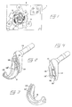
- Fig. 1 is a schematic front view of a rotation ring type barking machine;
- Fig. 2 is an enlarged perspective view of a tool according to the invention, included in the machine;
- Fig. 3 is a perspective view of a swinging arm included in the tool as shown in Fig. 2;
- Fig. 4 is a perspective view of a pivot shaft included in the tool, and the holder associated therewith;
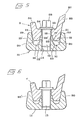
- Fig. 5 is a cross-sectional view of the tool in the assembled state, the screw connection being but partly screwed in; and
- Fig. 6 is the same cross-sectional view as in Fig. 5, but with the screw connection fully tightened.
-
Reference numeral 1 in Fig. 1 generally designates a barking machine which includes, besides a supporting frame orhousing 2, arotor 3 on which a number oftools 4 according to the invention are mounted. The embodiment illustrated comprises five tools, but this number may vary. Therotor 3 is annular, and through thehollow space 5 thereof alog 6 can be fed lengthwise by means of a suitable number of rotating rolls 7, for example three rolls which preferably are in the form of jagged rolls pivotally mounted injournals 8. It is pointed out that the jagged rolls 7 are distinctly separate from therotor 3 in a direction perpendicular to the plane of the drawing so that the rolls will not come into contact with the rotor. It is also pointed out that a corresponding set of feed rolls are mounted on the rear side of thehousing 2, such that a log can be fed before a log end has entered into contact with the tools, or discharged after a log end has lost contact with the tools. - The tool illustrated in Figs. 2-6 comprises the actual swinging
arm 9 and ashaft 10 which is journaled in therotor 3 and which at its end protruding from the rotor has aholder 11. Theholder 11 preferably is formed in one piece with theshaft 10, but may also be designed as a separate part which subsequently is firmly connected with theshaft 10. The swingingarm 9 is curved and has at its free end remote from the holder 11 aseat 12 adapted to accommodate a detachable cutting tool (not shown) which incorporates the cutting edge performing the actual barking operation. Instead of using a separate exchangeable cutting tool, it is also possible to form the cutting edge directly on the pivot shaft proper. - As will appear from Figs. 2-6, the swinging
arm 9 is detachably connected with theholder 11 via a screw connection which, in the embodiment illustrated, comprises twoscrews holes holder 11 and extend throughoblong holes arm 9. - In accordance with the principle of the invention, the
holder 11 is formed with twoelongated grooves intermediate ridge 17. These grooves are adapted to receive twobeads arm 9 and spaced apart by anintermediate recess 18. The two outerlateral faces grooves lateral faces beads lateral faces beads lateral faces outer faces grooves - The two
bead portions thin web portion 24. It is pointed out that the side of the swingingarm 9 first struck by a log fed into the machine has aflange 25 which is slightly higher than asimilar flange 26 on the opposite side of the arm and formed with a relativelysharp edge 27. The threadedholes ridge portion 17 of theholder 11, while theoblong holes web portion 24 of the swinging arm. Thescrew heads 28 may conveniently be in the form of square heads which are not notably higher than the lowestlateral flange 26 of the swinging arm, whereby the heads are accommodated by the protected space between theflanges - It is also pointed out that not only the
grooves beads oblong holes 15 are circularly curved, whereby the swinging arm can be displaced along a part-circular path relative to the holder. The displaceability makes it possible to adjust the swinging arm into different selecable positions relative to the holder for variation of the distance between the center of gravity of the swinging arm and the center of thepivot shaft 10. - In Fig. 5, the
screw 15 has been initially screwed into the threadedhole 14 but not finally tightened. In this condition, the outer slopinglateral faces lateral faces holder 11 only in theupper edge area 29, in that the angle of convergence between thelateral faces faces inner faces beads lateral faces grooves - When the two
screws beads grooves faces faces inner faces ridge 17. At this point, the swinging arm is stopped by the holder, and the torque required for pushing the swinging arm further inwardly relative to the holder is increased drastically. This torque is equivalent to the tensioning force with which the screws must be tightened to gain adequate gripping power for a long time. In this manner, there is conveniently obtained a specific and adequate tensioning force in the screw connection. - The above-mentioned reduction of the angular difference between the faces 20-20′ and 21-21′ is achieved by a partial deformation of the material of both the swinging arm and the holder, more particularly in the
lateral flanges thin web portion 24 of the swinging arm. - In the embodiment described above, the
grooves 16 are formed in theholder 11 and thebeads 19 in theswinging arm 19. However, the reverse is also possible, i.e. the grooves are formed in the swinging arm and the beads in the holder. The important thing is that the essentially W-shaped cross-sections of the two elements are maintained and made to cooperate in the manner described.
Claims (3)
Priority Applications (1)
| Application Number | Priority Date | Filing Date | Title |
|---|---|---|---|
| AT89850175T ATE94798T1 (en) | 1988-06-08 | 1989-05-30 | TOOL FOR DEBARKING MACHINES WITH ONE ROTATING RING. |
Applications Claiming Priority (2)
| Application Number | Priority Date | Filing Date | Title |
|---|---|---|---|
| SE8802141A SE463662B (en) | 1988-06-08 | 1988-06-08 | TOOLS FOR HALTING TYPE BARKING MACHINES |
| SE8802141 | 1988-06-08 |
Publications (3)
| Publication Number | Publication Date |
|---|---|
| EP0346309A2 true EP0346309A2 (en) | 1989-12-13 |
| EP0346309A3 EP0346309A3 (en) | 1991-09-25 |
| EP0346309B1 EP0346309B1 (en) | 1993-09-22 |
Family
ID=20372557
Family Applications (1)
| Application Number | Title | Priority Date | Filing Date |
|---|---|---|---|
| EP89850175A Expired - Lifetime EP0346309B1 (en) | 1988-06-08 | 1989-05-30 | Tool for rotation ring type barking machines |
Country Status (8)
| Country | Link |
|---|---|
| US (1) | US4872495A (en) |
| EP (1) | EP0346309B1 (en) |
| AT (1) | ATE94798T1 (en) |
| CA (1) | CA1316081C (en) |
| DE (1) | DE68909314T2 (en) |
| FI (1) | FI84704C (en) |
| NO (1) | NO170464C (en) |
| SE (1) | SE463662B (en) |
Families Citing this family (8)
| Publication number | Priority date | Publication date | Assignee | Title |
|---|---|---|---|---|
| USD315355S (en) | 1988-06-08 | 1991-03-12 | Mecania Ab | Debarking tool |
| USD336905S (en) | 1990-07-13 | 1993-06-29 | Mecania Ab | Swinging arm for a debarking tool |
| SE469117C (en) * | 1990-12-21 | 1997-12-08 | Soederhamns Verkstaeder Ab | Barking tools for hollow rotor barking machines |
| CA2131066C (en) * | 1994-08-29 | 2001-01-30 | Denis Johnson | Debarker arms and debarker tips for mounting on log barking machines |
| CA2207579A1 (en) * | 1997-05-28 | 1998-11-28 | Paul Caron | A sintered part with an abrasion-resistant surface and the process for producing it |
| USD419854S (en) | 1998-03-13 | 2000-02-01 | Forano International Inc. | Debarker arm |
| USD411097S (en) | 1998-08-05 | 1999-06-15 | Forano International Inc. | Holder for a debarker arm |
| USD903472S1 (en) * | 2019-07-17 | 2020-12-01 | Pmc Industries, Inc. | Top bracket for mounting device |
Family Cites Families (5)
| Publication number | Priority date | Publication date | Assignee | Title |
|---|---|---|---|---|
| US3709272A (en) * | 1971-07-08 | 1973-01-09 | R Bowers | Log debarking apparatus |
| SE415078B (en) * | 1974-09-25 | 1980-09-08 | Jonsson Karl Erik Arnold | DEBARKING TOOLS |
| SE430391B (en) * | 1977-11-11 | 1983-11-14 | Jonsson Karl Erik Arnold | WORKING BODY IN HALROTOR TYPE BARKING MACHINES |
| US4438794A (en) * | 1979-07-23 | 1984-03-27 | Carpenter Aaron R | Bark tool and connection |
| US4280541A (en) * | 1980-01-10 | 1981-07-28 | Reimler Associates, Inc. | Debarking tool for log debarking machines |
-
1988
- 1988-06-08 SE SE8802141A patent/SE463662B/en not_active IP Right Cessation
- 1988-10-26 CA CA000581379A patent/CA1316081C/en not_active Expired - Lifetime
- 1988-10-27 US US07/263,524 patent/US4872495A/en not_active Expired - Lifetime
-
1989
- 1989-05-30 EP EP89850175A patent/EP0346309B1/en not_active Expired - Lifetime
- 1989-05-30 AT AT89850175T patent/ATE94798T1/en not_active IP Right Cessation
- 1989-05-30 DE DE89850175T patent/DE68909314T2/en not_active Expired - Fee Related
- 1989-06-07 NO NO892342A patent/NO170464C/en not_active IP Right Cessation
- 1989-06-07 FI FI892800A patent/FI84704C/en not_active IP Right Cessation
Also Published As
| Publication number | Publication date |
|---|---|
| FI892800L (en) | 1989-12-09 |
| FI84704B (en) | 1991-09-30 |
| NO170464B (en) | 1992-07-13 |
| EP0346309B1 (en) | 1993-09-22 |
| SE8802141D0 (en) | 1988-06-08 |
| NO170464C (en) | 1992-10-21 |
| EP0346309A3 (en) | 1991-09-25 |
| US4872495A (en) | 1989-10-10 |
| DE68909314T2 (en) | 1994-04-21 |
| SE463662B (en) | 1991-01-07 |
| FI892800A0 (en) | 1989-06-07 |
| FI84704C (en) | 1992-01-10 |
| NO892342L (en) | 1989-12-11 |
| SE8802141L (en) | 1989-12-09 |
| NO892342D0 (en) | 1989-06-07 |
| CA1316081C (en) | 1993-04-13 |
| ATE94798T1 (en) | 1993-10-15 |
| DE68909314D1 (en) | 1993-10-28 |
Similar Documents
| Publication | Publication Date | Title |
|---|---|---|
| EP0502863B1 (en) | Cutting bit and block mount | |
| JP3392827B2 (en) | Chisel holder exchange system | |
| EP0830229B1 (en) | High-speed, cartridge-type milling cutter | |
| US20090205472A1 (en) | Mountings for riving knives of table saws | |
| EP0376204B1 (en) | Adjustable boring bar cartridge | |
| CA2386846A1 (en) | Milling cutter and cutting insert therefor | |
| EP0319499B1 (en) | Debarking means for rotation ring type barking machines | |
| EP0346309A2 (en) | Tool for rotation ring type barking machines | |
| US5816301A (en) | Knife supporting structure | |
| KR100259549B1 (en) | Multi-Oriented Milling Cutters with Indexable Wedge Supports and Inserts | |
| JPH0125642B2 (en) | ||
| US5081769A (en) | Cutter head with flexible stabilizer | |
| US5992199A (en) | Modular knurling tool | |
| US5080153A (en) | Blade adjusting means for the cutter heads of wood chippers | |
| JP2606628Y2 (en) | Stepless variable clamp tool | |
| EP0008798B1 (en) | A cutterhead for a portable power planer | |
| US5593253A (en) | Router bit with interchangeable knives | |
| JP3007291B2 (en) | Exchangeable tool support | |
| US4865095A (en) | Tool for rotation ring type barking machines | |
| US4484505A (en) | Carpet beveling head device | |
| CN216543529U (en) | Thin type edge tearing knife rest for printing paper processing | |
| JP2978674B2 (en) | Position adjustment device for circular saw blade of cutting machine | |
| JPH0445792Y2 (en) | ||
| JPH06344214A (en) | Milling cutter | |
| JPS5852881Y2 (en) | Chamfer plane stand for woodworking |
Legal Events
| Date | Code | Title | Description |
|---|---|---|---|
| PUAI | Public reference made under article 153(3) epc to a published international application that has entered the european phase |
Free format text: ORIGINAL CODE: 0009012 |
|
| AK | Designated contracting states |
Kind code of ref document: A2 Designated state(s): AT DE FR |
|
| PUAL | Search report despatched |
Free format text: ORIGINAL CODE: 0009013 |
|
| AK | Designated contracting states |
Kind code of ref document: A3 Designated state(s): AT DE FR |
|
| 17P | Request for examination filed |
Effective date: 19911206 |
|
| 17Q | First examination report despatched |
Effective date: 19920722 |
|
| GRAA | (expected) grant |
Free format text: ORIGINAL CODE: 0009210 |
|
| AK | Designated contracting states |
Kind code of ref document: B1 Designated state(s): AT DE FR |
|
| PG25 | Lapsed in a contracting state [announced via postgrant information from national office to epo] |
Ref country code: FR Effective date: 19930922 |
|
| REF | Corresponds to: |
Ref document number: 94798 Country of ref document: AT Date of ref document: 19931015 Kind code of ref document: T |
|
| REF | Corresponds to: |
Ref document number: 68909314 Country of ref document: DE Date of ref document: 19931028 |
|
| EN | Fr: translation not filed | ||
| PLBE | No opposition filed within time limit |
Free format text: ORIGINAL CODE: 0009261 |
|
| STAA | Information on the status of an ep patent application or granted ep patent |
Free format text: STATUS: NO OPPOSITION FILED WITHIN TIME LIMIT |
|
| 26N | No opposition filed | ||
| PGFP | Annual fee paid to national office [announced via postgrant information from national office to epo] |
Ref country code: AT Payment date: 20040521 Year of fee payment: 16 |
|
| PGFP | Annual fee paid to national office [announced via postgrant information from national office to epo] |
Ref country code: DE Payment date: 20040727 Year of fee payment: 16 |
|
| PG25 | Lapsed in a contracting state [announced via postgrant information from national office to epo] |
Ref country code: AT Free format text: LAPSE BECAUSE OF NON-PAYMENT OF DUE FEES Effective date: 20050530 |
|
| PG25 | Lapsed in a contracting state [announced via postgrant information from national office to epo] |
Ref country code: DE Free format text: LAPSE BECAUSE OF NON-PAYMENT OF DUE FEES Effective date: 20051201 |