EP0346183B1 - Prothèse à glissement pour le genou - Google Patents
Prothèse à glissement pour le genou Download PDFInfo
- Publication number
- EP0346183B1 EP0346183B1 EP19890401468 EP89401468A EP0346183B1 EP 0346183 B1 EP0346183 B1 EP 0346183B1 EP 19890401468 EP19890401468 EP 19890401468 EP 89401468 A EP89401468 A EP 89401468A EP 0346183 B1 EP0346183 B1 EP 0346183B1
- Authority
- EP
- European Patent Office
- Prior art keywords
- piece
- block
- endoprosthesis according
- tibial
- pairs
- Prior art date
- Legal status (The legal status is an assumption and is not a legal conclusion. Google has not performed a legal analysis and makes no representation as to the accuracy of the status listed.)
- Expired - Lifetime
Links
- 210000003127 knee Anatomy 0.000 title claims description 14
- 210000002303 tibia Anatomy 0.000 claims description 16
- 210000000689 upper leg Anatomy 0.000 claims description 15
- 239000000463 material Substances 0.000 claims description 9
- 229910052751 metal Inorganic materials 0.000 claims description 8
- 239000002184 metal Substances 0.000 claims description 8
- 238000005452 bending Methods 0.000 claims description 7
- 210000002967 posterior cruciate ligament Anatomy 0.000 claims description 6
- 210000000988 bone and bone Anatomy 0.000 claims description 5
- 230000001054 cortical effect Effects 0.000 claims description 3
- 229920001903 high density polyethylene Polymers 0.000 claims description 3
- 239000004700 high-density polyethylene Substances 0.000 claims description 3
- 210000004439 collateral ligament Anatomy 0.000 description 4
- 210000002414 leg Anatomy 0.000 description 4
- 238000007789 sealing Methods 0.000 description 3
- 230000005540 biological transmission Effects 0.000 description 2
- 239000004744 fabric Substances 0.000 description 2
- 230000002349 favourable effect Effects 0.000 description 2
- 150000002739 metals Chemical class 0.000 description 2
- GDOPTJXRTPNYNR-UHFFFAOYSA-N CC1CCCC1 Chemical compound CC1CCCC1 GDOPTJXRTPNYNR-UHFFFAOYSA-N 0.000 description 1
- DCHOHQFFTBQGRB-UHFFFAOYSA-N CS1C=CCC1 Chemical compound CS1C=CCC1 DCHOHQFFTBQGRB-UHFFFAOYSA-N 0.000 description 1
- 229910001069 Ti alloy Inorganic materials 0.000 description 1
- 230000037396 body weight Effects 0.000 description 1
- IUWCPXJTIPQGTE-UHFFFAOYSA-N chromium cobalt Chemical compound [Cr].[Co].[Co].[Co] IUWCPXJTIPQGTE-UHFFFAOYSA-N 0.000 description 1
- 239000000470 constituent Substances 0.000 description 1
- 238000010276 construction Methods 0.000 description 1
- 238000006073 displacement reaction Methods 0.000 description 1
- 210000000629 knee joint Anatomy 0.000 description 1
- 210000003041 ligament Anatomy 0.000 description 1
- 238000003754 machining Methods 0.000 description 1
- 238000012423 maintenance Methods 0.000 description 1
- 238000004519 manufacturing process Methods 0.000 description 1
- 238000005259 measurement Methods 0.000 description 1
- 210000002445 nipple Anatomy 0.000 description 1
- 230000000149 penetrating effect Effects 0.000 description 1
- 238000002271 resection Methods 0.000 description 1
- 239000010935 stainless steel Substances 0.000 description 1
- 229910001220 stainless steel Inorganic materials 0.000 description 1
- 238000006467 substitution reaction Methods 0.000 description 1
Images


Classifications
-
- A—HUMAN NECESSITIES
- A61—MEDICAL OR VETERINARY SCIENCE; HYGIENE
- A61F—FILTERS IMPLANTABLE INTO BLOOD VESSELS; PROSTHESES; DEVICES PROVIDING PATENCY TO, OR PREVENTING COLLAPSING OF, TUBULAR STRUCTURES OF THE BODY, e.g. STENTS; ORTHOPAEDIC, NURSING OR CONTRACEPTIVE DEVICES; FOMENTATION; TREATMENT OR PROTECTION OF EYES OR EARS; BANDAGES, DRESSINGS OR ABSORBENT PADS; FIRST-AID KITS
- A61F2/00—Filters implantable into blood vessels; Prostheses, i.e. artificial substitutes or replacements for parts of the body; Appliances for connecting them with the body; Devices providing patency to, or preventing collapsing of, tubular structures of the body, e.g. stents
- A61F2/02—Prostheses implantable into the body
- A61F2/30—Joints
- A61F2/38—Joints for elbows or knees
- A61F2/3868—Joints for elbows or knees with sliding tibial bearing
-
- A—HUMAN NECESSITIES
- A61—MEDICAL OR VETERINARY SCIENCE; HYGIENE
- A61F—FILTERS IMPLANTABLE INTO BLOOD VESSELS; PROSTHESES; DEVICES PROVIDING PATENCY TO, OR PREVENTING COLLAPSING OF, TUBULAR STRUCTURES OF THE BODY, e.g. STENTS; ORTHOPAEDIC, NURSING OR CONTRACEPTIVE DEVICES; FOMENTATION; TREATMENT OR PROTECTION OF EYES OR EARS; BANDAGES, DRESSINGS OR ABSORBENT PADS; FIRST-AID KITS
- A61F2/00—Filters implantable into blood vessels; Prostheses, i.e. artificial substitutes or replacements for parts of the body; Appliances for connecting them with the body; Devices providing patency to, or preventing collapsing of, tubular structures of the body, e.g. stents
- A61F2/02—Prostheses implantable into the body
- A61F2/30—Joints
- A61F2/38—Joints for elbows or knees
- A61F2/3886—Joints for elbows or knees for stabilising knees against anterior or lateral dislocations
Definitions
- the present invention relates to a knee endoprosthesis as defined in the first part of claim 1
- the embodiment which has been described has certain drawbacks which make it hardly usable in practice, because in fact corresponding only to cases limited to knees whose ligaments are destroyed, whereas in many cases it is possible to keep at least the posterior cruciate ligament, in addition to the lateral ligaments.
- connection between the parts by axis and roller moving in a slot provided on one of the parts causes metal-to-metal friction, at least between the ends of the axis and the walls of the femoral part between which the roller is placed, which is harmful.
- the presence of the oblong opening for guiding the roller requires great precision in the machining of this opening or of the difficult adjustments, so that the sliding surfaces of different spokes are in correct support during the operation of the joint.
- the two parts respectively integral with the femur and the tibia, and which are in sliding contact on parallel supports, some convex and the other concave, shaped with two spokes of different curvature to achieve the movement in two stages, are simply applied one against the other by said supports, without a material articulation axis.
- the rotation which accompanies the knee flexion is ensured simply by the cooperation of the shaped supports which can rotate while sliding on each other.
- the tibial piece of conical outer shape receives a nested conical support plate also symmetrically provided with two sliding tracks for the convex surfaces of the femoral piece. These two tracks have only the large radius of curvature R, so that in the folding of the knee, the parts of the femoral part with small radius r come punctually to touch the tibial part.
- the sliding parts which is made of a material with a low coefficient of friction, such as high density polyethylene, and which is carried by a metal support integral with the tibia, is produced in the form of a plate. thick of which two opposite edges carry the concave supports conformed to the respective radii and which is provided with means of connection to the tibial part.
- Said plate is preferably removably fixed on its metal support, which allows its rapid change as its replacement by a more or less thick plate to adjust the prosthesis to the wearer.
- the device for fixing the wafer is advantageously of the kind with rotation connection about an axis which is housed in the wafer. This allows a certain mobility in vertical rotation of the tibia, as in the natural joint.
- the femoral piece which is in one piece and whose shape recalls that of a saddle, comprises, on its face facing the femur, housings in which the condyles of the femur can fit together, previously shaped and adjusted, as well as one or more several appendages intended to be sealed in the femur.
- the tibial piece is in the form of a plate, provided with a sealing appendage in the medullary canal of the tibia, and wide enough to rest on the cortical part of the bone which alone has the resistance necessary to support the weight. from the body. It also carries one or two eccentric appendages which, penetrating into the bone, ensure its fixity.
- the combination of these means provides a prosthesis which, while having the advantages of the cooperation of sliding surfaces of different radii, restoring the movement of the natural joint and not requiring significant bone resection, is furthermore of simple constitution, easy adjustment, better suited to the requirements of a prosthesis and in many cases to keep the posterior cruciate ligament in addition to the lateral ligaments.
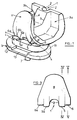
- Figure 1 is a perspective view of the prosthesis in a first embodiment suitable for the conservation of the lateral ligaments.
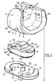
- Figure 2 also shows in perspective, but separated, the three constituent parts of the prosthesis.
- Figure 3 is a front view of the part (a).
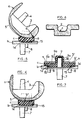
- Figures 4 and 5 are sections through IV-IV and V-V showing the prosthesis seen from the side, respectively leg in extension ( Figure 4) and in flexion ( Figure 5).
- Figure 6 is a section along VI-VI.
- Figure 7 shows in section the edge of the plate and illustrates its fixing device, on the tibial part.
- Figures 8 to 12 relate to another embodiment of the prosthesis which has advantageous features.
- Figure 8 is a perspective view of this embodiment.
- Figure 9 is a front view of the femoral part.
- Figure 10 is a section along X-X.
- Figures 11 and 12 show a horizontal projection view of the tibial pad and a sectional view along XII-XII.
- a designates the part or piece of the prosthesis which is integral with the femur.
- a groove 1 delimited by two parallel cheeks 2
- a relief 3 on the back of the part whose shape recalls that of a saddle.
- an appendix 4 intended to be sealed in the medullary canal of the femur whose condyles, suitably prepared and adjusted, are housed astride relief 3, in the cavities such as 3a and 3b which exist on both sides. other of this relief.
- the outer face of the part a has the support ramps 5, 6 and 5a, 6a shaped with different radii.
- the part b integral with the tibia, is constituted by a metal plate carrying below an appendage 7 for the sealing in the medial channel of the tibia, as well as two smaller appendages such as 8 which are introduced into the end of the tibia suitably shaped to prevent displacement.
- the plate constituting the part b has a sufficient surface to rest on the cortical part of the tibia which is the most resistant.
- this plate includes a boss 9 which has come from manufacturing with the plate, and carrying a blind cylindrical hole in which engages, during assembly, a cylindrical pin 10 provided on the upper face of the tibial plate b .
- the boss 9 comprises two opposite flats 9a separated by a distance which is equal, apart from play, to the interval between the cheeks 2 of the groove 1 existing on the femoral part a .
- the plate c on the tibial part b it is hollowed out on its upper surface so as to leave in relief, at its ends, two half-crowns 11 and 12, separated by a gap 13 very slightly larger that the width of the plate c .
- the half-rings in relief 11, 12 have at their base a semi-circular groove 14, which corresponds to the underside of the wafer c a semi-circular projecting collar 15 ( Figure 7).
- the tibial piece b has in its center, on its upper face, a cylindrical stud 10 which can engage with gentle friction in the blind hole of the boss 10 of the plate c .
- the metal femoral part a cooperates with the plate c made of a material with low coefficient of friction, linked to the tibial part b , to allow the sliding c on a at the same time as the rotation which accompany the bending of the knee, and this without axis articulation material.
- the plate Near its small edges and on either side of the boss 9, the plate has two symmetrical pairs of sliding paths or concave ramps 5 ', 6';5'a,6'a which cooperate with two symmetrical pairs of sliding paths or convex ramps 5, 6; 5a, 6a provided on the femoral part a , on either side of the groove 1.
- the concave ramps as well as the corresponding convex ramps constitute four associated pairs (5, 5'- 6, 6'- 5a, 5'a and 6a, 6'a) located in four different parallel planes, as can be seen on the Figures 1, 2, 3, 7 and 11.
- the ramps 5 and 5 'and the cooperating ramps 5a, 5'a have the greatest radius of curvature large, equal to the radius of the anterior aspect of the condyles of the femur. It is the spoke which has been called R in the above mentioned utility certificate and which is used for walking.
- sliding paths 6 'and 6'a are each supplemented by a projection s which opposes posterior dislocation of the knee by replacing or completing the function of the posterior cruciate ligament.
- the femoral part a is hollowed out for this purpose from a wide slot 20 having its origin at 21 at the bottom of the anterior face of the femoral part.
- the remaining wings 22 and 23 are each provided with an appendage 24 (one of them is hidden in Figure 8) for sealing on the femur.
- the wings 22 and 23 On their face facing the plate c , the wings 22 and 23 have the convex sliding surfaces 5, 6, 5a, 6a cooperating respectively with the concave surfaces 5 ', 6', 5'a, 6'a of the plate.
- the boss 9 of the plate is eliminated, the pivot 10 being short enough to be accommodated in the thickness of the plate. .
- the femoral part is guided on the plate by increasing --- the projection of the sliding surfaces 5, 5a, relative to the surfaces 6, 6a and by reciprocally conforming the cooperating concave surfaces 5 ', 5'a, 6 ', 6'a of the brochure. Thanks to this measure, a good fitting of the femoral part on the wafer is obtained, and this fitting ensures the guidance.
- the metals used, on the tibia side, as on the femur side, are of the stainless steel, chromium-cobalt or titanium alloy type, all compatible with fabrics. However, without departing from the scope of the invention, all or part of the metals may be replaced by a hard material compatible with fabrics.
Landscapes
- Health & Medical Sciences (AREA)
- Orthopedic Medicine & Surgery (AREA)
- Physical Education & Sports Medicine (AREA)
- Cardiology (AREA)
- Oral & Maxillofacial Surgery (AREA)
- Transplantation (AREA)
- Engineering & Computer Science (AREA)
- Biomedical Technology (AREA)
- Heart & Thoracic Surgery (AREA)
- Vascular Medicine (AREA)
- Life Sciences & Earth Sciences (AREA)
- Animal Behavior & Ethology (AREA)
- General Health & Medical Sciences (AREA)
- Public Health (AREA)
- Veterinary Medicine (AREA)
- Prostheses (AREA)
Description
- La présente invention concerne une endoprothèse du genou telle que définie dans la première partie de la revendication 1
- Dans son certificat d'utilité 84.10261 du 28 Juin 1984 (numéro de publication 2 566 657), la demanderesse a décrit une endoprothèse à glissement pour le genou, comprenant deux pièces solidaires respectivement du tibia et du fémur et une pièce intermédiaire en matière à faible coefficient de frottement, cette pièce et la pièce fémorale pouvant glisser l'une sur l'autre par des surfaces comportant deux fractions qui viennent successivement en appui lors du mouvement de flexion, les rayons de ces fractions étant différents et correspondant aux centres de rotation de l'articulation naturelle. Cette endoprothèse présente par rapport aux prothèses antérieures connues un certain nombre d'avantages importants qui ont été indiqués dans le préambule dudit certificat d'utilité.
- Toutefois, le mode de réalisation qui a été décrit présente certains inconvénients qui le rendent peu utilisable en pratique, parce que ne correspondant en fait qu'à des cas limités à des genoux dont les ligaments sont détruits, alors que dans de nombreux cas on peut conserver au moins le ligament croisé postérieur, en plus des ligaments latéraux.
- La liaison entre les pièces par axe et galet se déplaçant dans une fente prévue sur l'une des pièces, entraîne un frottement métal sur métal, au moins entre les extrémités de l'axe et les parois de la pièce fémorale entre lesquelles le galet est placé, ce qui est nuisible.
- D'autre part, le montage de cette liaison nécessite que l'un des flasques soit démontable, ce qui requiert la présence de vis pour la fixation de ce flasque.
- Par ailleurs la présence de l'ouverture oblongue pour le guidage du galet nécessite une grande précision dans l'usinage de cette ouverture ou des ajustages difficiles, afin que les surfaces de glissement de rayons différents soient en appui correct lors du fonctionnement de l'articulation.
- L'invention permet d'éviter ces inconvénients et d'obtenir d'autres avantages qui ressortiront de la description suivante.
- Dans l'endoprothèse perfectionnée qui fait l'objet de l'invention, les deux parties, solidaires respectivement du fémur et du tibia, et qui sont en contact glissant sur des appuis parallèles, les uns convexes et les autres concaves, conformés avec deux rayons de courbure différents pour réaliser le mouvement en deux temps, sont simplement appliquées l'une contre l'autre par lesdits appuis, sans axe d'articulation matériel. De la sorte, la rotation qui accompagne la flexion du genou est assurée simplement par la coopération des appuis conformés qui peuvent tourner en glissant les uns sur les autres.
- Il est vrai que dans le brevet anglais GB-A-2 120 943, sur lequel se fonde le préambule de la revendication 1, a déjà été décrit une prothèse à glissement sans axe matériel entre les pièces fémorales et tibiales qui s'appuient et glissent l'une sur l'autre. Dans cette prothèse la pièce fémorale de forme conique présente de chaque côté du plan de symétrie de l'ensemble, une surface de glissement convexe comportant à l'avant, une première partie à grand rayon de courbure et à l'arrière immédiatement à la suite de la première partie, une seconde partie également convexe mais de rayon de courbure r plus petit, comme dans l'articulation naturelle. La pièce tibiale de forme extérieure conique reçoit une plaquette d'appui emboîtée également conique munie symétriquement de deux pistes de glissement pour les surfaces convexes de la pièce fémorale. Ces deux pistes ont seulement le grand rayon de courbure R, de sorte que dans le repliement du genou, les parties de la pièce fémorale à petit rayon r viennent toucher ponctuellement la pièce tibiale.
- Il résulte de ce contact, qui se fait uniquement le long d'une générative des surfaces, que la pression transmise à la pièce tibiale par la pièce fémorale peut devenir très élevée en entraînant une usure rapide des surfaces de glissement.
- Des mesures ont en effet montré qu'en raison de la variation des bras de levier, lors d'une rotation du fémur par rapport au tibia par exemple dans le franchissement d'un escalier, la force transmise au tibia par le fémur peut atteindre ou même dépasser le quadruple du poids du corps.
- Cet inconvénient est évité dans la prothèse selon l'invention grâce aux particularités exposées dans la revendication 1.
- Dans une telle disposition, il est possible de caler angulairement les surfaces d'appui de grand et de petit rayon respectivement, de manière que dans la flexion du genou, les surfaces de petit rayon de la pièce fémorale commencent à épouser les surfaces correspondantes de la pièce tibiale avant que les surfaces correspondantes de la pièce tibiale avant que les surfaces de grand rayon se séparent et ainsi qu'un appui de surface soit maintenu.
- Une autre particularité de la prothèse est que celle des parties glissantes qui est en matière à faible coefficient de frottement, telle que du polyéthylène haute densité, et qui est portée par un support métallique solidaire du tibia, est réalisée sous la forme d'une plaquette épaisse dont deux bords opposés portent les appuis concaves conformés aux rayons respectifs et qui est munie de moyens de liaison à la pièce tibiale.
- Ladite plaquette est de préférence fixée de façon amovible sur son support métallique, ce qui permet son changement rapide comme son remplacement par une plaquette plus ou moins épaisse pour ajuster la prothése au porteur.
- Le dispositif de fixation de la plaquette est avantageusement du genre à liaison par rotation autour d'un axe qui se loge dans la plaquette. Ceci permet de disposer d'une certaine mobilité en rotation verticale du tibia, comme dans l'articulation naturelle.
- Au contraire dans le brevet anglais 2 120 943, l'encastrement de la plaquette à contour polygonal dans la pièce tibiale, ne lui permet pas de tourner dans cette pièce, de sorte que la facilité de rotation autour de l'axe du tibia, qui existe dans l'articulation naturelle, fait défaut.
- La pièce fémorale, qui est monobloc et dont la forme rappelle celle d'une selle, comporte, sur sa face tournée vers le fémur, des logements où peuvent s'emboîter les condyles du fémur, préalablement conformés et ajustés, ainsi qu'un ou plusieurs appendices destinés à être scellés dans le fémur. Un bon appui entre la pièce et l'os, favorable à une transmission correcte des efforts et à la fixité en rotation, est ainsi assuré.
- La pièce tibiale a la forme d'une plaque, munie d'un appendice de scellement dans le canal médullaire du tibia, et assez large pour s'appuyer sur la partie corticale de l'os qui seule a la résistance nécessaire pour supporter le poids du corps. Elle porte en outre un ou deux appendices excentrés qui, en pénétrant dans l'os, assurent sa fixité.
- La combinaison de ces moyens procure une prothèse qui, tout en présentant les avantages de la coopération de surfaces glissantes de rayons différents, restituant le mouvement de l'articulation naturelle et n'exigeant pas de résection osseuse importante, est en outre de constitution simple, de réglage facile, mieux adaptée aux désidérata auxquels doit satisfaire une prothèse et permettant dans de nombreux cas de conserver le ligament croisé postérieur en plus des ligaments latéraux.
- Dans ce qui suit, on décrira en regard du dessin annexé deux modes de réalisation particuliers de la prothèse perfectionnée, donnés à titre d'exemple non limitatif.
- La figure 1 est une vue en perspective de la prothèse dans un premier mode de réalisation convenant à la conservation des ligaments latéraux.
- La figure 2 montre également en perspective, mais séparées, les trois parties constitutives de la prothèse.
- La figure 3 est une vue de face de la pièce (a).
- Les figures 4 et 5 sont des coupes par IV-IV et V-V montrant la prothèse vue de côté, respectivement jambe en extension (figure 4) et en flexion (figure 5).
- La figure 6 est une coupe selon VI-VI.
- La figure 7 montre en coupe le bord de la plaquette et illustre son dispositif de fixation, sur la pièce tibiale.
- Les figures 8 à12 sont relatives à un autre mode de réalisation de la prothèse qui comporte des particularités avantageuses.
- La figure 8 est une vue en perspective de ce mode de réalisation.
- La figure 9 est une vue de face de la pièce fémorale.
- La figure 10 est une coupe selon X-X.
- Les figures 11 et 12 montrent une vue en projection horizontale de la plaquette tibiale et une vue en coupe selon XII-XII.
- Sur le dessin, a désigne la partie ou pièce de la prothèse qui est solidaire du fémur. Dans le mode de réalisation des figures 1 à 7, une rainure 1, délimitée par deux joues parallèles 2, se poursuit d'avant en arrière en procurant un relief 3 sur le dos de la pièce dont la forme rappelle celle d'une selle. Sur ce relief se trouve un appendice 4 destiné à être scellé dans le canal médullaire du fémur dont les condyles, convenablement préparés et ajustés, viennent se loger à cheval sur le relief 3, dans les cavités telles que 3a et 3b qui existent de part et d'autre de ce relief. On obtient ainsi entre le fémur et la pièce a de la prothèse une liaison favorable à la bonne transmission des efforts et à sa fixité.
- La face extérieure de la pièce a comporte les rampes d'appui 5, 6 et 5a, 6a conformées avec des rayons différents.
- La pièce b, solidaire du tibia, est constituée par une plaque en métal portant en-dessous un appendice 7 pour le scellement dans le canal médulaire du tibia, ainsi que deux appendices plus petits tels que 8 qui sont introduits dans l'extrémité du tibia convenablement conformée, pour empêcher tout déplacement. La plaque constituant la pièce b a une surface suffisante pour s'appuyer sur la partie corticale du tibia qui est la plus résistante.
- Entre les deux parties a et b se trouve une plaquette c de forme oblongue et relativement épaisse, en matière à faible coefficient de frottement, telle que le polyéthylène haute densité. En son centre cette plaquette comporte un bossage 9 venu de fabrication avec la plaquette, et portant un trou cylindrique borgne dans lequel vient s'engager, lors de l'assemblage, un téton cylindrique 10 prévu sur la face supérieure de la plaque tibiale b.
- Le bossage 9 comporte deux méplats opposés 9a séparés par une distance qui est égale, au jeu près, à l'intervalle entre les joues 2 de la rainure 1 existant sur la pièce fémorale a.
- Pour la fixation de la plaquette c sur la pièce tibiale b, celle-ci est évidée sur sa surface supérieure de manière à laisser en relief, à ses extrémités, deux demi-couronnes 11 et 12, séparées par un intervalle 13 très légèrement plus grand que la largeur de la plaquette c. De plus, les demi-couronnes en relief 11, 12 présentent à leur base une rainure semi-circulaire 14, à laquelle correspond sur la face inférieure de la plaquette c une collerette semi-circulaire en saillie 15 (figure 7). Enfin la pièce tibiale b comporte en son centre, sur sa face supérieure, un téton cylindrique 10 qui peut s'engager à frottement doux dans le trou borgne du bossage 10 de la plaquette c.
- Pour fixer celle-ci sur la pièce tibiale b, on engage le téton 10 dans le trou du bossage 9, en présentant la plaquette c perpendiculairement à la position qu'elle occupe sur la figure 2, de manière qu'elle repose sur la partie centrale de la pièce b en s'emboîtant dans les intervalles 13 entre les demi-couronnes 11 et 12, puis on fait tourner la plaquette de 90° de manière que les collerettes 15 s'engagent dans les rainures 14, en solidarisant ainsi les pièces b et c dans les position angulaires relatives que montre la figure 2.
- On remarque la facilité de ce montage qui offre des possibilités de remplacement rapide de la plaquette c ou pour mettre une plaquette plus ou moins épaisse afin d'ajuster la prothèse à la morphologie du porteur.
- On remarque aussi que le montage laisse une faculté de rotation d'un petit angle, sans désassemblage, autour de l'axe du tibia (axe du téton 10) comme dans l'articulation naturelle.
- La pièce fémorale en métal a coopère avec la plaquette c en matière à faible coefficient de frottement, liée à la pièce tibiale b, pour permettre le glissement c sur a en même temps que la rotation qui accompagnent la flexion du genou, et ce sans axe matériel d'articulation.
- Près de ses petits bords et de part et d'autre du bossage 9, la plaquette comporte deux paires symétriques de chemins de glissement ou rampes concaves 5', 6' ; 5'a, 6'a qui coopèrent avec deux paires symétriques de chemins de glissement ou rampes convexes 5, 6 ; 5a, 6a prévues sur la pièce fémorale a, de part et d'autre de la rainure 1.
- Les rampes concaves ainsi que les rampes convexes correspondantes constituent quatre paires associées (5, 5'- 6, 6'- 5a, 5'a et 6a, 6'a) situées dans quatre plans parallèles différentes, comme on le voit bien sur les figures 1, 2, 3, 7 et 11.
- Les rampes 5 et 5' ainsi que les rampes coopérantes 5a, 5'a ont le rayon de courbure le plus grand, égal au rayon de la face antérieure des condyles du fémur. C'est le rayon qui a été appelé R dans le certificat d'utilité susmentionné et qui sert à la marche.
- Quand la jambe est en extension (figure 4), les rampes 5 et 5a s'appuient sur les rampes 5' et 5'a respectivement et, comme les rayons de courbure sont les mêmes, l'appui se fait sur pratiquement toute la surface des rampes 5' et 5'a de la plaquette, surface qui peut être rendue importante par construction. On peut donc supprimer complètement l'inconvénient des charges ponctuelles.
- Quand on fléchit la jambe, le début de la flexion se fait encore par appui des rampes 5 et 5a sur les rampes 5' et 5'a du même rayon, ceci jusqu'à un angle de flexion d'environ 35 à 40°, les rampes 5 et 5a étant suffisamment prolongées sur la pièce fémorale a.
- A ce moment, les rampes 6 et 6a de la pièce fémorale a qui ont un rayon de courbure plus petit r et qui ont commencé à être au contact des rampes convexes correspondantes 6', 6'a de même rayon, prévues sur la plaquette, viennent en coïncidence avec ces rampes (figure 5), tandis que les rampes 5 et 5a sont hors d'action. Dans ce cas encore, l'appui des pièces se fait sur une surface importante.
- Il est important que le calage angulaire des rampes d'appui de grand et de petit rayon soit tel que les rampes de petit rayon 6 et 6a viennent épouser les rampes correspondantes 6' et 6'a de la plaquette c, avant que les rampes 5 et 5a de grand rayon cessent leur action. On peut ainsi obtenir une continuité dans le mouvement tout en évitant les charges ponctuelles.
- De plus, les chemins de glissement 6' et 6'a sont complétés chacun par une saillie s qui s'oppose à une luxation postérieure du genou en remplaçant ou complétant la fonction du ligament croisé postérieur.
- Le maintien en appui des pièces de la prothèse, quand le pied n'est pas en appui sur le sol, résulte de l'action des ligaments latéraux de l'articulation naturelle.
- Le mode de réalisation qui va maintenant être décrit en regard des figures 8 à 12 a été conçu pour tenir compte de la possibilité avantageuse de conserver le ligament croisé postérieur de l'articulation du genou.
- La pièce fémorale a est évidée à cet effet d'une large fente 20 ayant son origine en 21 au bas de la face antérieure de la pièce fémorale. De part et d'autre de cette fente les ailes restantes 22 et 23 sont munies chacune d'un appendice 24 (l'un d'eux est caché sur la figure 8) pour le scellement sur le fémur. Sur leur face tournée vers la plaquette c, les ailes 22 et 23 comportent les surfaces de glissement convexes 5, 6, 5a, 6a coopérant respectivement avec les surfaces concaves 5', 6', 5'a, 6'a de la plaquette.
- Comme la fente 20 doit rester libre pour le passage du ligament croisé postérieur de l'articulation naturelle le bossage 9 de la plaquette, ci-dessus décrit, est supprimé, le pivot 10 étant assez court pour se loger dans l'épaisseur de la plaquette. Le guidage de la pièce fémorale sur la plaquette est assuré en augmentant --- la saillie des surfaces glissantes 5, 5a, par rapport aux surfaces 6, 6a et en conformant de façon réciproque les surfaces concaves coopérantes 5', 5'a, 6', 6'a de la plaquette. Grâce à cette mesure on obtient un bon emboitement de la pièce fémorale sur la plaquette, et cet emboîtement assure le guidage.
- On voit bien sur les figures 10 à 12 les surfaces convexes à grand rayon (centre 26) de la pièce fémorale qui ont un assez fort relief par rapport aux surfaces de petit rayon dont le centre est en 27 quand la jambe est en extension. Réciproquement les surfaces concaves de petit rayon 6', 6'a de la plaquette c ont un certain relief par rapport aux surfaces concaves de grand rayon 5', 5'a de cette plaquette. Pour illustrer ce relief qui assure le maintien de l'emboitement de guidage, lors de la flexion du genou, on l'a représenté en grisé sur les figures 10 et 12.
- 28 désigne le joint où s'arrêtent les surfaces à grand rayon 5 et 5a et où commencent les surfaces à petit rayon 6 et 6a.
- Les métaux utilisés, côté tibia, comme côté fémur, sont du type acier inoxydable, alliages chrome-cobalt ou titane, tous compatibles avec les tissus. Mais on pourrait sans sortir du cadre de l'invention remplacer tout ou partie des métaux par un matériau dur, compatible avec les tissus.
- Il va d'ailleurs de soi que les modes de réalisation décrits pourraient être modifiés, notamment par substitution d'équivalents techniques, sans que l'on sorte pour cela du cadre de l'invention.
Claims (10)
- Endoprothèse du genou dans laquelle deux parties, liées respectivement au fémur et au tibia, et qui sont en contact glissant par des surfaces conformées avec deux rayons de courbure différents (R respectivement r) correspondant aux rayons de courbure de l'articulation naturelle et de même centres que ceux de cette articulation, les mises en coïncidence successives des surfaces coopérantes lors de la flexion du genou, se faisant par un simple guidage de ces surfaces en appui mutuel, sans axes d'articulation matériel, caractérisée en ce que la pièce tibiale (6) comporte deux paires de surfaces d'appui et de glissement (5', 5'a, 6', 6'a) concaves et situées dans des plans différentes symétriquement placés par rapport au plan de symétrie vertical de la prothèse, les surfaces (5', 5'a) de l'une des paires ayant le grand rayon de courbure (R) et les surfaces (6', 6'a) de l'autre paire ayant le petit rayon de courbure (r) tandis que la pièce fémorale (a) comporte deux paires de surfaces d'appui et de glissement convexes (5, 5a, 6, 6a), correspondant dans leur symétrie et leurs rayons aux surfaces respectives de la pièce tibiale.
- Endoprothèse selon la revendication 1, caractérisée par un calage angulaire des surfaces d'appui de grand et de petit rayon respectivement, tel que dans la flexion du genou les surfaces de petit rayon (6, 6') de la pièce fémorale commencent à épouser les surfaces correspondantes (6a, 6'a) de la pièce tibiale, avant que les surfaces de grand rayon (5, 5', 5a, 5'a) se séparent, de manière à maintenir un appui de surface.
- Endroprothèse selon l'une des revendications 1 et 2, dans laquelle l'une des parties glissantes (C) est en matière à faible coefficient de frottement, telle que du polyéthylène haute densité, caractérisée en ce que ladite partie est en forme de plaquette épaisse sur laquelle sont évidées symétriquement et parallèlement, les paires de surfaces concaves d'appui conformées (5', 6', 5'a, 6'a) homologues des paires de surfaces convexes (5, 6, 5a, 6a) prévues sur la pièce fémorale (a).
- Endoprothèse selon la revendication 3, caractérisée en ce que la plaquette (c) est munie d'un bossage central à méplats (9) de petite hauteur, introduit et guidé dans une rainure (1) à bords parallèles de la partie en métal (a) solidaire du fémur qui est monobloc.
- Endoprothèse selon l'une des revendications 3 et 4, caractérisée en ce que la plaquette (c) est fixée de façon amovible sur un support métallique (b) destiné à être solidarisé du tibia.
- Endoprothèse selon la revendication 5, caractérisée en ce que le dispositif de fixation de la plaquette est du genre à liaison par rotation autour d'un pivot porté par la pièce tibiale (b) et se logeant dans la plaquette.
- Endoprothèse selon la revendication 6, caractérisée en ce que le dispositif de fixation de la plaquette est agencé pour permettre en fonctionnement, une petite rotation de la plaquette autour de son pivot.
- Endoprothèse selon la revendication 6, caractérisée en ce que la pièce tibiale (b) se compose d'un support métallique en forme de plaque, assez large pour s'appuyer sur la partie corticale de l'os et munie vers ses extrémités de deux demi-couronnes en saillie (11, 12) comportant une rainure semi-circulaire (14) dans laquelle vient s'engager par rotation une collerette (15) de la plaquette (c) en matière à faible coefficient de frottement.
- Endoprothèse selon l'une des revendications 1 à 3 et 5 à 8, caractérisée en ce que le guidage de la pièce tibiale (b et c) par rapport à la pièce fémorale (a) lors de la flexion du genou est assuré par le fait qu'une paire de surfaces cylindriques de glissement (5, 5a) est décalée en hauteur par rapport à l'autre paire (6, 6a) avec un décalage correspondant dans les autres surfaces coopérantes (5', 5'a et 6', 6'a) de manière que le relief ainsi créé assure un emboîtement s'opposant aux mouvements relatifs latéraux des pièces.
- Endoprothèse selon la revendication 9, caractérisée en ce que la partie postérieure de la pièce fémorale comporte une large fente médiane (20) entre les paires (5-6, 5a-6a) de surfaces coopérantes pour le passage du ligament croisé postérieur de l'articulation naturelle.
Applications Claiming Priority (2)
| Application Number | Priority Date | Filing Date | Title |
|---|---|---|---|
| FR8807205 | 1988-05-31 | ||
| FR8807205A FR2631814A1 (fr) | 1988-05-31 | 1988-05-31 | Prothese a glissement pour le genou |
Publications (2)
| Publication Number | Publication Date |
|---|---|
| EP0346183A1 EP0346183A1 (fr) | 1989-12-13 |
| EP0346183B1 true EP0346183B1 (fr) | 1993-04-21 |
Family
ID=9366757
Family Applications (1)
| Application Number | Title | Priority Date | Filing Date |
|---|---|---|---|
| EP19890401468 Expired - Lifetime EP0346183B1 (fr) | 1988-05-31 | 1989-05-30 | Prothèse à glissement pour le genou |
Country Status (3)
| Country | Link |
|---|---|
| EP (1) | EP0346183B1 (fr) |
| DE (1) | DE68906082T2 (fr) |
| FR (1) | FR2631814A1 (fr) |
Cited By (51)
| Publication number | Priority date | Publication date | Assignee | Title |
|---|---|---|---|---|
| US6413279B1 (en) | 1999-03-01 | 2002-07-02 | Biomet, Inc. | Floating bearing knee joint prosthesis with a fixed tibial post |
| US6726723B2 (en) | 1998-09-21 | 2004-04-27 | Depuy Orthopaedics, Inc. | Posterior stabilized mobile bearing knee |
| US7500983B1 (en) | 2004-06-09 | 2009-03-10 | Biomet Sports Medicine, Llc | Apparatus for soft tissue attachment |
| US7520901B2 (en) | 2001-06-14 | 2009-04-21 | Alexandria Research Technologies, Inc. | Bicompartmental implants and method of use |
| US7601165B2 (en) | 2006-09-29 | 2009-10-13 | Biomet Sports Medicine, Llc | Method and apparatus for forming a self-locking adjustable suture loop |
| US7608092B1 (en) | 2004-02-20 | 2009-10-27 | Biomet Sports Medicince, LLC | Method and apparatus for performing meniscus repair |
| US7695503B1 (en) | 2004-06-09 | 2010-04-13 | Biomet Sports Medicine, Llc | Method and apparatus for soft tissue attachment |
| US7749250B2 (en) | 2006-02-03 | 2010-07-06 | Biomet Sports Medicine, Llc | Soft tissue repair assembly and associated method |
| US7819898B2 (en) | 2004-06-09 | 2010-10-26 | Biomet Sports Medicine, Llc | Method and apparatus for soft tissue fixation |
| US7828820B2 (en) | 2006-03-21 | 2010-11-09 | Biomet Sports Medicine, Llc | Method and apparatuses for securing suture |
| US7857830B2 (en) | 2006-02-03 | 2010-12-28 | Biomet Sports Medicine, Llc | Soft tissue repair and conduit device |
| US7905904B2 (en) | 2006-02-03 | 2011-03-15 | Biomet Sports Medicine, Llc | Soft tissue repair device and associated methods |
| US7905903B2 (en) | 2006-02-03 | 2011-03-15 | Biomet Sports Medicine, Llc | Method for tissue fixation |
| US7909851B2 (en) | 2006-02-03 | 2011-03-22 | Biomet Sports Medicine, Llc | Soft tissue repair device and associated methods |
| US7959650B2 (en) | 2006-09-29 | 2011-06-14 | Biomet Sports Medicine, Llc | Adjustable knotless loops |
| US8088130B2 (en) | 2006-02-03 | 2012-01-03 | Biomet Sports Medicine, Llc | Method and apparatus for coupling soft tissue to a bone |
| US8109965B2 (en) | 2004-06-09 | 2012-02-07 | Biomet Sports Medicine, LLP | Method and apparatus for soft tissue fixation |
| US8118836B2 (en) | 2004-11-05 | 2012-02-21 | Biomet Sports Medicine, Llc | Method and apparatus for coupling soft tissue to a bone |
| US8128658B2 (en) | 2004-11-05 | 2012-03-06 | Biomet Sports Medicine, Llc | Method and apparatus for coupling soft tissue to bone |
| US8137382B2 (en) | 2004-11-05 | 2012-03-20 | Biomet Sports Medicine, Llc | Method and apparatus for coupling anatomical features |
| US8251998B2 (en) | 2006-08-16 | 2012-08-28 | Biomet Sports Medicine, Llc | Chondral defect repair |
| US8298262B2 (en) | 2006-02-03 | 2012-10-30 | Biomet Sports Medicine, Llc | Method for tissue fixation |
| US8303604B2 (en) | 2004-11-05 | 2012-11-06 | Biomet Sports Medicine, Llc | Soft tissue repair device and method |
| US8317825B2 (en) | 2004-11-09 | 2012-11-27 | Biomet Sports Medicine, Llc | Soft tissue conduit device and method |
| US8343227B2 (en) | 2009-05-28 | 2013-01-01 | Biomet Manufacturing Corp. | Knee prosthesis assembly with ligament link |
| US8361113B2 (en) | 2006-02-03 | 2013-01-29 | Biomet Sports Medicine, Llc | Method and apparatus for coupling soft tissue to a bone |
| US8500818B2 (en) | 2006-09-29 | 2013-08-06 | Biomet Manufacturing, Llc | Knee prosthesis assembly with ligament link |
| US8506597B2 (en) | 2011-10-25 | 2013-08-13 | Biomet Sports Medicine, Llc | Method and apparatus for interosseous membrane reconstruction |
| US8562647B2 (en) | 2006-09-29 | 2013-10-22 | Biomet Sports Medicine, Llc | Method and apparatus for securing soft tissue to bone |
| US8562645B2 (en) | 2006-09-29 | 2013-10-22 | Biomet Sports Medicine, Llc | Method and apparatus for forming a self-locking adjustable loop |
| US8574235B2 (en) | 2006-02-03 | 2013-11-05 | Biomet Sports Medicine, Llc | Method for trochanteric reattachment |
| US8597327B2 (en) | 2006-02-03 | 2013-12-03 | Biomet Manufacturing, Llc | Method and apparatus for sternal closure |
| US8652171B2 (en) | 2006-02-03 | 2014-02-18 | Biomet Sports Medicine, Llc | Method and apparatus for soft tissue fixation |
| US8652172B2 (en) | 2006-02-03 | 2014-02-18 | Biomet Sports Medicine, Llc | Flexible anchors for tissue fixation |
| US8672969B2 (en) | 2006-09-29 | 2014-03-18 | Biomet Sports Medicine, Llc | Fracture fixation device |
| US8771352B2 (en) | 2011-05-17 | 2014-07-08 | Biomet Sports Medicine, Llc | Method and apparatus for tibial fixation of an ACL graft |
| US8801783B2 (en) | 2006-09-29 | 2014-08-12 | Biomet Sports Medicine, Llc | Prosthetic ligament system for knee joint |
| US8840645B2 (en) | 2004-11-05 | 2014-09-23 | Biomet Sports Medicine, Llc | Method and apparatus for coupling soft tissue to a bone |
| US8936621B2 (en) | 2006-02-03 | 2015-01-20 | Biomet Sports Medicine, Llc | Method and apparatus for forming a self-locking adjustable loop |
| US8968364B2 (en) | 2006-02-03 | 2015-03-03 | Biomet Sports Medicine, Llc | Method and apparatus for fixation of an ACL graft |
| US8998949B2 (en) | 2004-11-09 | 2015-04-07 | Biomet Sports Medicine, Llc | Soft tissue conduit device |
| US9017381B2 (en) | 2007-04-10 | 2015-04-28 | Biomet Sports Medicine, Llc | Adjustable knotless loops |
| US9078644B2 (en) | 2006-09-29 | 2015-07-14 | Biomet Sports Medicine, Llc | Fracture fixation device |
| US9149267B2 (en) | 2006-02-03 | 2015-10-06 | Biomet Sports Medicine, Llc | Method and apparatus for coupling soft tissue to a bone |
| US9259217B2 (en) | 2012-01-03 | 2016-02-16 | Biomet Manufacturing, Llc | Suture Button |
| US9271713B2 (en) | 2006-02-03 | 2016-03-01 | Biomet Sports Medicine, Llc | Method and apparatus for tensioning a suture |
| US9314241B2 (en) | 2011-11-10 | 2016-04-19 | Biomet Sports Medicine, Llc | Apparatus for coupling soft tissue to a bone |
| US9357991B2 (en) | 2011-11-03 | 2016-06-07 | Biomet Sports Medicine, Llc | Method and apparatus for stitching tendons |
| US9370350B2 (en) | 2011-11-10 | 2016-06-21 | Biomet Sports Medicine, Llc | Apparatus for coupling soft tissue to a bone |
| US9381013B2 (en) | 2011-11-10 | 2016-07-05 | Biomet Sports Medicine, Llc | Method for coupling soft tissue to a bone |
| US9538998B2 (en) | 2006-02-03 | 2017-01-10 | Biomet Sports Medicine, Llc | Method and apparatus for fracture fixation |
Families Citing this family (63)
| Publication number | Priority date | Publication date | Assignee | Title |
|---|---|---|---|---|
| US4888021A (en) * | 1988-02-02 | 1989-12-19 | Joint Medical Products Corporation | Knee and patellar prosthesis |
| DE69128961T2 (de) * | 1990-11-14 | 1998-10-08 | Arch Development Corp., Chicago, Ill. | Verbesserte knieprothese mit beweglichem lager |
| ATE137950T1 (de) * | 1991-01-18 | 1996-06-15 | Sulzer Medizinaltechnik Ag | Kniegelenkprothese |
| FR2672798B1 (fr) * | 1991-02-19 | 1998-01-30 | Erato | Prothese du genou. |
| US5203807A (en) * | 1991-07-10 | 1993-04-20 | Smith & Nephew Richards Inc. | Knee joint prosthesis articular surface |
| US5470354A (en) * | 1991-11-12 | 1995-11-28 | Biomet Inc. | Force sensing apparatus and method for orthopaedic joint reconstruction |
| FR2685632B1 (fr) * | 1991-12-31 | 1995-08-04 | Procom Sa | Ensemble prothetique pour la realisation d'une prothese du genou. |
| FR2691356B1 (fr) * | 1992-05-20 | 1999-07-23 | Bouvet Jean Claude | Prothese de genou. |
| DE69319332D1 (de) * | 1993-04-05 | 1998-07-30 | Procom S A | Prothesenteile zum Aufbau eines Kniegelenks |
| IT1277091B1 (it) * | 1994-12-30 | 1997-11-04 | Jbs Sa | Protesi di ripresa stabilizzata da dietro per articolazione del ginocchio |
| AUPN089495A0 (en) * | 1995-02-03 | 1995-03-02 | Denupo Pty. Ltd. | Knee prosthesis |
| US5683468A (en) * | 1995-03-13 | 1997-11-04 | Pappas; Michael J. | Mobile bearing total joint replacement |
| FR2735017B1 (fr) * | 1995-06-08 | 1997-08-14 | Groupe Lepine | Prothese de genou a plateau mobile |
| US5871543A (en) * | 1996-02-23 | 1999-02-16 | Hofmann; Aaron A. | Tibial prosthesis with mobile bearing member |
| FR2750036B1 (fr) * | 1996-06-19 | 1998-11-27 | Martin Jean Jacques | Ensemble d'elements pour la constitution d'une prothese de genou |
| US5964808A (en) * | 1996-07-11 | 1999-10-12 | Wright Medical Technology, Inc. | Knee prosthesis |
| GB2323034B (en) * | 1997-03-13 | 2001-07-25 | Zimmer Ltd | Prosthesis for knee replacement |
| US6039764A (en) * | 1997-08-18 | 2000-03-21 | Arch Development Corporation | Prosthetic knee with adjusted center of internal/external rotation |
| FR2768613B1 (fr) * | 1997-09-23 | 1999-12-17 | Tornier Sa | Prothese de genou a plateau rotatoire |
| US6010534A (en) * | 1997-09-25 | 2000-01-04 | Johnson & Johnson Professional, Inc. | Rotatable tibial prosthesis with keyed axial securement |
| US6053945A (en) * | 1997-09-25 | 2000-04-25 | Johnson & Johnson Professional, Inc. | Joint prosthesis having controlled rotation |
| US5951603A (en) * | 1997-09-25 | 1999-09-14 | Johnson & Johnson Professional, Inc. | Rotatable joint prosthesis with axial securement |
| AUPP000797A0 (en) * | 1997-10-24 | 1997-11-20 | Cryptych Pty Ltd | Fixation of cruciate ligament grafts |
| FR2772259B1 (fr) * | 1997-12-12 | 2000-03-03 | Tornier Sa | Perfectionnements apportes aux protheses totales de genou comportant un element femoral et un plateau tibial |
| US6123729A (en) * | 1998-03-10 | 2000-09-26 | Bristol-Myers Squibb Company | Four compartment knee |
| US6972039B2 (en) | 1999-03-01 | 2005-12-06 | Biomet, Inc. | Floating bearing knee joint prosthesis with a fixed tibial post |
| US6210444B1 (en) * | 1999-10-26 | 2001-04-03 | Bristol-Myers Squibb Company | Tibial knee component with a mobile bearing |
| DE10012060C2 (de) * | 2000-03-14 | 2002-10-31 | Saint Paul Bernd | Endoprothese für ein Kniegelenk |
| US6503280B2 (en) * | 2000-12-26 | 2003-01-07 | John A. Repicci | Prosthetic knee and method of inserting |
| FR2838330B1 (fr) * | 2002-04-12 | 2005-03-04 | Medical Solution | Ensemble tibial pour l'articulation du genou |
| US6946001B2 (en) * | 2003-02-03 | 2005-09-20 | Zimmer Technology, Inc. | Mobile bearing unicompartmental knee |
| DE10220591B4 (de) * | 2002-05-08 | 2004-03-18 | Mathys Medizinaltechnik Ag | Gelenkprothese mit Zwischenelement mit unterschiedlichen Krümmungsradien |
| JP4045194B2 (ja) * | 2003-02-25 | 2008-02-13 | 京セラ株式会社 | 人工膝関節 |
| US7544209B2 (en) | 2004-01-12 | 2009-06-09 | Lotke Paul A | Patello-femoral prosthesis |
| US8535383B2 (en) | 2004-01-12 | 2013-09-17 | DePuy Synthes Products, LLC | Systems and methods for compartmental replacement in a knee |
| US8002840B2 (en) | 2004-01-12 | 2011-08-23 | Depuy Products, Inc. | Systems and methods for compartmental replacement in a knee |
| CN1972646B (zh) | 2004-01-12 | 2010-05-26 | 德普伊产品公司 | 用于膝中隔间置换的系统和方法 |
| US9801708B2 (en) | 2004-11-05 | 2017-10-31 | Biomet Sports Medicine, Llc | Method and apparatus for coupling soft tissue to a bone |
| US11259792B2 (en) | 2006-02-03 | 2022-03-01 | Biomet Sports Medicine, Llc | Method and apparatus for coupling anatomical features |
| US11311287B2 (en) | 2006-02-03 | 2022-04-26 | Biomet Sports Medicine, Llc | Method for tissue fixation |
| US10517587B2 (en) | 2006-02-03 | 2019-12-31 | Biomet Sports Medicine, Llc | Method and apparatus for forming a self-locking adjustable loop |
| US11259794B2 (en) | 2006-09-29 | 2022-03-01 | Biomet Sports Medicine, Llc | Method for implanting soft tissue |
| US9918826B2 (en) | 2006-09-29 | 2018-03-20 | Biomet Sports Medicine, Llc | Scaffold for spring ligament repair |
| US12502169B2 (en) | 2007-01-16 | 2025-12-23 | Biomet Sports Medicine, Llc | Soft tissue repair device and associated methods |
| FR2916136B1 (fr) * | 2007-05-18 | 2009-08-21 | Patrick Hechard | Partie de prothese apte a etre implantee sur une extremite resequee d'un os long |
| DE102007037154B4 (de) * | 2007-08-07 | 2011-05-19 | Aequos Endoprothetik Gmbh | Künstliches Gelenk und ein zu diesem Einsatz bestimmtes Gelenkteil |
| US12419632B2 (en) | 2008-08-22 | 2025-09-23 | Biomet Sports Medicine, Llc | Method and apparatus for coupling anatomical features |
| US12245759B2 (en) | 2008-08-22 | 2025-03-11 | Biomet Sports Medicine, Llc | Method and apparatus for coupling soft tissue to bone |
| US12096928B2 (en) | 2009-05-29 | 2024-09-24 | Biomet Sports Medicine, Llc | Method and apparatus for coupling soft tissue to a bone |
| US12551209B2 (en) | 2009-06-22 | 2026-02-17 | Biomet Sports Medicine, Llc | Method and apparatus for coupling soft tissue to a bone |
| US12616462B2 (en) | 2009-09-30 | 2026-05-05 | Biomet Sports Medicine, Llc | Soft tissue repair device and method |
| US8308808B2 (en) | 2010-02-19 | 2012-11-13 | Biomet Manufacturing Corp. | Latent mobile bearing for prosthetic device |
| US12329373B2 (en) | 2011-05-02 | 2025-06-17 | Biomet Sports Medicine, Llc | Method and apparatus for soft tissue fixation |
| US12582395B2 (en) | 2011-11-03 | 2026-03-24 | Biomet Sports Medicine, Llc | Method and apparatus for forming a self-locking adjustable loop |
| US9757119B2 (en) | 2013-03-08 | 2017-09-12 | Biomet Sports Medicine, Llc | Visual aid for identifying suture limbs arthroscopically |
| US9918827B2 (en) | 2013-03-14 | 2018-03-20 | Biomet Sports Medicine, Llc | Scaffold for spring ligament repair |
| US10136886B2 (en) | 2013-12-20 | 2018-11-27 | Biomet Sports Medicine, Llc | Knotless soft tissue devices and techniques |
| US9615822B2 (en) | 2014-05-30 | 2017-04-11 | Biomet Sports Medicine, Llc | Insertion tools and method for soft anchor |
| US9700291B2 (en) | 2014-06-03 | 2017-07-11 | Biomet Sports Medicine, Llc | Capsule retractor |
| US10039543B2 (en) | 2014-08-22 | 2018-08-07 | Biomet Sports Medicine, Llc | Non-sliding soft anchor |
| US9955980B2 (en) | 2015-02-24 | 2018-05-01 | Biomet Sports Medicine, Llc | Anatomic soft tissue repair |
| US9974534B2 (en) | 2015-03-31 | 2018-05-22 | Biomet Sports Medicine, Llc | Suture anchor with soft anchor of electrospun fibers |
| CN105030384B (zh) * | 2015-08-03 | 2018-04-10 | 北京威高亚华人工关节开发有限公司 | 一种全膝关节置换假体 |
Family Cites Families (5)
| Publication number | Priority date | Publication date | Assignee | Title |
|---|---|---|---|---|
| US4081866A (en) * | 1977-02-02 | 1978-04-04 | Howmedica, Inc. | Total anatomical knee prosthesis |
| US4353135A (en) * | 1980-05-09 | 1982-10-12 | Minnesota Mining And Manufacturing Company | Patellar flange and femoral knee-joint prosthesis |
| GB2120943B (en) * | 1982-03-13 | 1985-04-11 | Thackray C F Ltd | Knee prosthesis |
| EP0135319A3 (fr) * | 1983-08-24 | 1985-07-24 | ARTHROPLASTY RESEARCH & DEVELOPMENT (PTY) LTD. | Prothèse d'articulation du genou |
| FR2566657B3 (fr) * | 1984-06-28 | 1986-12-19 | Etude Rech Nles Protheses | Prothese du genou a glissement |
-
1988
- 1988-05-31 FR FR8807205A patent/FR2631814A1/fr not_active Withdrawn
-
1989
- 1989-05-30 DE DE1989606082 patent/DE68906082T2/de not_active Expired - Lifetime
- 1989-05-30 EP EP19890401468 patent/EP0346183B1/fr not_active Expired - Lifetime
Cited By (90)
| Publication number | Priority date | Publication date | Assignee | Title |
|---|---|---|---|---|
| US6726723B2 (en) | 1998-09-21 | 2004-04-27 | Depuy Orthopaedics, Inc. | Posterior stabilized mobile bearing knee |
| US6413279B1 (en) | 1999-03-01 | 2002-07-02 | Biomet, Inc. | Floating bearing knee joint prosthesis with a fixed tibial post |
| US7520901B2 (en) | 2001-06-14 | 2009-04-21 | Alexandria Research Technologies, Inc. | Bicompartmental implants and method of use |
| US7896922B2 (en) | 2001-06-14 | 2011-03-01 | Alexandria Research Technologies, Llc | Implants for partial knee arthroplasty |
| US8221454B2 (en) | 2004-02-20 | 2012-07-17 | Biomet Sports Medicine, Llc | Apparatus for performing meniscus repair |
| US7608092B1 (en) | 2004-02-20 | 2009-10-27 | Biomet Sports Medicince, LLC | Method and apparatus for performing meniscus repair |
| US7819898B2 (en) | 2004-06-09 | 2010-10-26 | Biomet Sports Medicine, Llc | Method and apparatus for soft tissue fixation |
| US8491632B2 (en) | 2004-06-09 | 2013-07-23 | Biomet Sports Medicine, Llc | Method and apparatus for soft tissue fixation |
| US8109965B2 (en) | 2004-06-09 | 2012-02-07 | Biomet Sports Medicine, LLP | Method and apparatus for soft tissue fixation |
| US7776077B2 (en) | 2004-06-09 | 2010-08-17 | Biomet Sports Medicince, LLC | Method for soft tissue attachment |
| US7500983B1 (en) | 2004-06-09 | 2009-03-10 | Biomet Sports Medicine, Llc | Apparatus for soft tissue attachment |
| US7695503B1 (en) | 2004-06-09 | 2010-04-13 | Biomet Sports Medicine, Llc | Method and apparatus for soft tissue attachment |
| US7967843B2 (en) | 2004-06-09 | 2011-06-28 | Biomet Sports Medicine, Llc | Method for soft tissue attachment |
| US8308780B2 (en) | 2004-06-09 | 2012-11-13 | Biomet Sports Medicine, Llc | Method for soft tissue attachment |
| US8137382B2 (en) | 2004-11-05 | 2012-03-20 | Biomet Sports Medicine, Llc | Method and apparatus for coupling anatomical features |
| US8128658B2 (en) | 2004-11-05 | 2012-03-06 | Biomet Sports Medicine, Llc | Method and apparatus for coupling soft tissue to bone |
| US9504460B2 (en) | 2004-11-05 | 2016-11-29 | Biomet Sports Medicine, LLC. | Soft tissue repair device and method |
| US8303604B2 (en) | 2004-11-05 | 2012-11-06 | Biomet Sports Medicine, Llc | Soft tissue repair device and method |
| US8551140B2 (en) | 2004-11-05 | 2013-10-08 | Biomet Sports Medicine, Llc | Method and apparatus for coupling soft tissue to bone |
| US8118836B2 (en) | 2004-11-05 | 2012-02-21 | Biomet Sports Medicine, Llc | Method and apparatus for coupling soft tissue to a bone |
| US8840645B2 (en) | 2004-11-05 | 2014-09-23 | Biomet Sports Medicine, Llc | Method and apparatus for coupling soft tissue to a bone |
| US8998949B2 (en) | 2004-11-09 | 2015-04-07 | Biomet Sports Medicine, Llc | Soft tissue conduit device |
| US8317825B2 (en) | 2004-11-09 | 2012-11-27 | Biomet Sports Medicine, Llc | Soft tissue conduit device and method |
| US8597327B2 (en) | 2006-02-03 | 2013-12-03 | Biomet Manufacturing, Llc | Method and apparatus for sternal closure |
| US9414833B2 (en) | 2006-02-03 | 2016-08-16 | Biomet Sports Medicine, Llc | Soft tissue repair assembly and associated method |
| US9561025B2 (en) | 2006-02-03 | 2017-02-07 | Biomet Sports Medicine, Llc | Soft tissue repair device and associated methods |
| US9538998B2 (en) | 2006-02-03 | 2017-01-10 | Biomet Sports Medicine, Llc | Method and apparatus for fracture fixation |
| US8273106B2 (en) | 2006-02-03 | 2012-09-25 | Biomet Sports Medicine, Llc | Soft tissue repair and conduit device |
| US8292921B2 (en) | 2006-02-03 | 2012-10-23 | Biomet Sports Medicine, Llc | Soft tissue repair device and associated methods |
| US8298262B2 (en) | 2006-02-03 | 2012-10-30 | Biomet Sports Medicine, Llc | Method for tissue fixation |
| US9532777B2 (en) | 2006-02-03 | 2017-01-03 | Biomet Sports Medicine, Llc | Method and apparatus for coupling soft tissue to a bone |
| US7909851B2 (en) | 2006-02-03 | 2011-03-22 | Biomet Sports Medicine, Llc | Soft tissue repair device and associated methods |
| US7905903B2 (en) | 2006-02-03 | 2011-03-15 | Biomet Sports Medicine, Llc | Method for tissue fixation |
| US8337525B2 (en) | 2006-02-03 | 2012-12-25 | Biomet Sports Medicine, Llc | Soft tissue repair device and associated methods |
| US9510819B2 (en) | 2006-02-03 | 2016-12-06 | Biomet Sports Medicine, Llc | Soft tissue repair device and associated methods |
| US8361113B2 (en) | 2006-02-03 | 2013-01-29 | Biomet Sports Medicine, Llc | Method and apparatus for coupling soft tissue to a bone |
| US8409253B2 (en) | 2006-02-03 | 2013-04-02 | Biomet Sports Medicine, Llc | Soft tissue repair assembly and associated method |
| US7905904B2 (en) | 2006-02-03 | 2011-03-15 | Biomet Sports Medicine, Llc | Soft tissue repair device and associated methods |
| US9492158B2 (en) | 2006-02-03 | 2016-11-15 | Biomet Sports Medicine, Llc | Method and apparatus for coupling soft tissue to a bone |
| US8932331B2 (en) | 2006-02-03 | 2015-01-13 | Biomet Sports Medicine, Llc | Method and apparatus for coupling soft tissue to bone |
| US9468433B2 (en) | 2006-02-03 | 2016-10-18 | Biomet Sports Medicine, Llc | Method and apparatus for forming a self-locking adjustable loop |
| US7857830B2 (en) | 2006-02-03 | 2010-12-28 | Biomet Sports Medicine, Llc | Soft tissue repair and conduit device |
| US8936621B2 (en) | 2006-02-03 | 2015-01-20 | Biomet Sports Medicine, Llc | Method and apparatus for forming a self-locking adjustable loop |
| US9402621B2 (en) | 2006-02-03 | 2016-08-02 | Biomet Sports Medicine, LLC. | Method for tissue fixation |
| US8574235B2 (en) | 2006-02-03 | 2013-11-05 | Biomet Sports Medicine, Llc | Method for trochanteric reattachment |
| US8968364B2 (en) | 2006-02-03 | 2015-03-03 | Biomet Sports Medicine, Llc | Method and apparatus for fixation of an ACL graft |
| US8608777B2 (en) | 2006-02-03 | 2013-12-17 | Biomet Sports Medicine | Method and apparatus for coupling soft tissue to a bone |
| US8632569B2 (en) | 2006-02-03 | 2014-01-21 | Biomet Sports Medicine, Llc | Soft tissue repair device and associated methods |
| US8652171B2 (en) | 2006-02-03 | 2014-02-18 | Biomet Sports Medicine, Llc | Method and apparatus for soft tissue fixation |
| US8652172B2 (en) | 2006-02-03 | 2014-02-18 | Biomet Sports Medicine, Llc | Flexible anchors for tissue fixation |
| US9271713B2 (en) | 2006-02-03 | 2016-03-01 | Biomet Sports Medicine, Llc | Method and apparatus for tensioning a suture |
| US9173651B2 (en) | 2006-02-03 | 2015-11-03 | Biomet Sports Medicine, Llc | Soft tissue repair device and associated methods |
| US8721684B2 (en) | 2006-02-03 | 2014-05-13 | Biomet Sports Medicine, Llc | Method and apparatus for coupling anatomical features |
| US8771316B2 (en) | 2006-02-03 | 2014-07-08 | Biomet Sports Medicine, Llc | Method and apparatus for coupling anatomical features |
| US9149267B2 (en) | 2006-02-03 | 2015-10-06 | Biomet Sports Medicine, Llc | Method and apparatus for coupling soft tissue to a bone |
| US8088130B2 (en) | 2006-02-03 | 2012-01-03 | Biomet Sports Medicine, Llc | Method and apparatus for coupling soft tissue to a bone |
| US9005287B2 (en) | 2006-02-03 | 2015-04-14 | Biomet Sports Medicine, Llc | Method for bone reattachment |
| US7749250B2 (en) | 2006-02-03 | 2010-07-06 | Biomet Sports Medicine, Llc | Soft tissue repair assembly and associated method |
| US7828820B2 (en) | 2006-03-21 | 2010-11-09 | Biomet Sports Medicine, Llc | Method and apparatuses for securing suture |
| US8506596B2 (en) | 2006-03-21 | 2013-08-13 | Biomet Sports Medicine, Llc | Methods and apparatuses for securing suture |
| US8777956B2 (en) | 2006-08-16 | 2014-07-15 | Biomet Sports Medicine, Llc | Chondral defect repair |
| US8251998B2 (en) | 2006-08-16 | 2012-08-28 | Biomet Sports Medicine, Llc | Chondral defect repair |
| US8231654B2 (en) | 2006-09-29 | 2012-07-31 | Biomet Sports Medicine, Llc | Adjustable knotless loops |
| US7658751B2 (en) | 2006-09-29 | 2010-02-09 | Biomet Sports Medicine, Llc | Method for implanting soft tissue |
| US8500818B2 (en) | 2006-09-29 | 2013-08-06 | Biomet Manufacturing, Llc | Knee prosthesis assembly with ligament link |
| US9078644B2 (en) | 2006-09-29 | 2015-07-14 | Biomet Sports Medicine, Llc | Fracture fixation device |
| US9681940B2 (en) | 2006-09-29 | 2017-06-20 | Biomet Sports Medicine, Llc | Ligament system for knee joint |
| US8672968B2 (en) | 2006-09-29 | 2014-03-18 | Biomet Sports Medicine, Llc | Method for implanting soft tissue |
| US8562647B2 (en) | 2006-09-29 | 2013-10-22 | Biomet Sports Medicine, Llc | Method and apparatus for securing soft tissue to bone |
| US9486211B2 (en) | 2006-09-29 | 2016-11-08 | Biomet Sports Medicine, Llc | Method for implanting soft tissue |
| US8801783B2 (en) | 2006-09-29 | 2014-08-12 | Biomet Sports Medicine, Llc | Prosthetic ligament system for knee joint |
| US8672969B2 (en) | 2006-09-29 | 2014-03-18 | Biomet Sports Medicine, Llc | Fracture fixation device |
| US9539003B2 (en) | 2006-09-29 | 2017-01-10 | Biomet Sports Medicine, LLC. | Method and apparatus for forming a self-locking adjustable loop |
| US7959650B2 (en) | 2006-09-29 | 2011-06-14 | Biomet Sports Medicine, Llc | Adjustable knotless loops |
| US9414925B2 (en) | 2006-09-29 | 2016-08-16 | Biomet Manufacturing, Llc | Method of implanting a knee prosthesis assembly with a ligament link |
| US7601165B2 (en) | 2006-09-29 | 2009-10-13 | Biomet Sports Medicine, Llc | Method and apparatus for forming a self-locking adjustable suture loop |
| US8562645B2 (en) | 2006-09-29 | 2013-10-22 | Biomet Sports Medicine, Llc | Method and apparatus for forming a self-locking adjustable loop |
| US9017381B2 (en) | 2007-04-10 | 2015-04-28 | Biomet Sports Medicine, Llc | Adjustable knotless loops |
| US8343227B2 (en) | 2009-05-28 | 2013-01-01 | Biomet Manufacturing Corp. | Knee prosthesis assembly with ligament link |
| US8900314B2 (en) | 2009-05-28 | 2014-12-02 | Biomet Manufacturing, Llc | Method of implanting a prosthetic knee joint assembly |
| US9216078B2 (en) | 2011-05-17 | 2015-12-22 | Biomet Sports Medicine, Llc | Method and apparatus for tibial fixation of an ACL graft |
| US8771352B2 (en) | 2011-05-17 | 2014-07-08 | Biomet Sports Medicine, Llc | Method and apparatus for tibial fixation of an ACL graft |
| US8506597B2 (en) | 2011-10-25 | 2013-08-13 | Biomet Sports Medicine, Llc | Method and apparatus for interosseous membrane reconstruction |
| US9445827B2 (en) | 2011-10-25 | 2016-09-20 | Biomet Sports Medicine, Llc | Method and apparatus for intraosseous membrane reconstruction |
| US9357991B2 (en) | 2011-11-03 | 2016-06-07 | Biomet Sports Medicine, Llc | Method and apparatus for stitching tendons |
| US9381013B2 (en) | 2011-11-10 | 2016-07-05 | Biomet Sports Medicine, Llc | Method for coupling soft tissue to a bone |
| US9370350B2 (en) | 2011-11-10 | 2016-06-21 | Biomet Sports Medicine, Llc | Apparatus for coupling soft tissue to a bone |
| US9357992B2 (en) | 2011-11-10 | 2016-06-07 | Biomet Sports Medicine, Llc | Method for coupling soft tissue to a bone |
| US9314241B2 (en) | 2011-11-10 | 2016-04-19 | Biomet Sports Medicine, Llc | Apparatus for coupling soft tissue to a bone |
| US9259217B2 (en) | 2012-01-03 | 2016-02-16 | Biomet Manufacturing, Llc | Suture Button |
Also Published As
| Publication number | Publication date |
|---|---|
| EP0346183A1 (fr) | 1989-12-13 |
| DE68906082T2 (de) | 1993-10-28 |
| FR2631814A1 (fr) | 1989-12-01 |
| DE68906082D1 (de) | 1993-05-27 |
Similar Documents
| Publication | Publication Date | Title |
|---|---|---|
| EP0346183A1 (fr) | Prothèse à glissement pour le genou | |
| CA2726034C (fr) | Prothese totale de genou | |
| CA1258554A (fr) | Composant femoral de prothese de hanche, non cimente | |
| CA1193051A (fr) | Prothese totale du genou | |
| EP0758218A1 (fr) | Prothese du genou a menisque mobile | |
| EP0684804A1 (fr) | Prothese totale du genou | |
| WO1998025550A1 (fr) | Prothese totale d'articulation du genou | |
| FR2634373A1 (fr) | Prothese totale du genou | |
| FR2760353A1 (fr) | Prothese de cheville | |
| EP0582514A1 (fr) | Prothèse du genou | |
| EP1380274A1 (fr) | Prothèse d'épaule ou de hanche facilitant l'abduction | |
| EP1196118A1 (fr) | Nouvelle prothese du genou | |
| FR2777452A1 (fr) | Prothese de genou | |
| BE1011626A3 (fr) | Prothese totale de genou a plateau tibial mobile en rotation. | |
| FR2712799A1 (fr) | Prothèse totale de genou et ensemble prothétique modulable de genou correspondant. | |
| EP2585001B1 (fr) | Dispositif orthopedique destine a equiper l'articulation d'un genou | |
| FR2664492A1 (fr) | Prothese bicondylienne du genou. | |
| FR2700260A1 (fr) | Pièce rotulienne artificielle pour prothèse de genou. | |
| EP0749734A1 (fr) | Prothèse totale d'articulation du genou | |
| BE1012454A3 (fr) | Appareil d'assistance ou de suppleance du genou. | |
| FR2835178A1 (fr) | Ensemble prothetique tibial pour prothese du genou a glissement | |
| FR2805456A1 (fr) | Prothese totale de genou, du type dit "postero-stabilisee" | |
| FR2696927A1 (fr) | Prothèse totale du genou. | |
| FR2684291A1 (fr) | Prothese de cheville. | |
| FR2735017A1 (fr) | Prothese de genou a plateau mobile |
Legal Events
| Date | Code | Title | Description |
|---|---|---|---|
| PUAI | Public reference made under article 153(3) epc to a published international application that has entered the european phase |
Free format text: ORIGINAL CODE: 0009012 |
|
| AK | Designated contracting states |
Kind code of ref document: A1 Designated state(s): CH DE FR GB IT LI |
|
| 17P | Request for examination filed |
Effective date: 19900511 |
|
| 17Q | First examination report despatched |
Effective date: 19920219 |
|
| GRAA | (expected) grant |
Free format text: ORIGINAL CODE: 0009210 |
|
| AK | Designated contracting states |
Kind code of ref document: B1 Designated state(s): CH DE FR GB IT LI |
|
| REF | Corresponds to: |
Ref document number: 68906082 Country of ref document: DE Date of ref document: 19930527 |
|
| ITF | It: translation for a ep patent filed | ||
| GBT | Gb: translation of ep patent filed (gb section 77(6)(a)/1977) |
Effective date: 19930714 |
|
| PLBE | No opposition filed within time limit |
Free format text: ORIGINAL CODE: 0009261 |
|
| STAA | Information on the status of an ep patent application or granted ep patent |
Free format text: STATUS: NO OPPOSITION FILED WITHIN TIME LIMIT |
|
| 26N | No opposition filed | ||
| REG | Reference to a national code |
Ref country code: FR Ref legal event code: TP |
|
| ITPR | It: changes in ownership of a european patent |
Owner name: CESSIONE;TORNIER S.A. |
|
| REG | Reference to a national code |
Ref country code: CH Ref legal event code: PUE Owner name: TORNIER S.A. |
|
| REG | Reference to a national code |
Ref country code: GB Ref legal event code: 732E |
|
| REG | Reference to a national code |
Ref country code: GB Ref legal event code: IF02 |
|
| PGFP | Annual fee paid to national office [announced via postgrant information from national office to epo] |
Ref country code: DE Payment date: 20080514 Year of fee payment: 20 Ref country code: CH Payment date: 20080515 Year of fee payment: 20 |
|
| PGFP | Annual fee paid to national office [announced via postgrant information from national office to epo] |
Ref country code: IT Payment date: 20080520 Year of fee payment: 20 |
|
| PGFP | Annual fee paid to national office [announced via postgrant information from national office to epo] |
Ref country code: GB Payment date: 20080506 Year of fee payment: 20 |
|
| REG | Reference to a national code |
Ref country code: CH Ref legal event code: PL |
|
| REG | Reference to a national code |
Ref country code: GB Ref legal event code: PE20 Expiry date: 20090529 |
|
| PG25 | Lapsed in a contracting state [announced via postgrant information from national office to epo] |
Ref country code: GB Free format text: LAPSE BECAUSE OF EXPIRATION OF PROTECTION Effective date: 20090529 |
|
| PGFP | Annual fee paid to national office [announced via postgrant information from national office to epo] |
Ref country code: FR Payment date: 20080429 Year of fee payment: 20 |