EP0345871A1 - Dispositif pour reproduire des images vidéo numérisées avec une restauration d'erreurs à plan incliné - Google Patents
Dispositif pour reproduire des images vidéo numérisées avec une restauration d'erreurs à plan incliné Download PDFInfo
- Publication number
- EP0345871A1 EP0345871A1 EP89201387A EP89201387A EP0345871A1 EP 0345871 A1 EP0345871 A1 EP 0345871A1 EP 89201387 A EP89201387 A EP 89201387A EP 89201387 A EP89201387 A EP 89201387A EP 0345871 A1 EP0345871 A1 EP 0345871A1
- Authority
- EP
- European Patent Office
- Prior art keywords
- picture
- picture elements
- prediction
- erroneous
- elements
- Prior art date
- Legal status (The legal status is an assumption and is not a legal conclusion. Google has not performed a legal analysis and makes no representation as to the accuracy of the status listed.)
- Granted
Links
Images


Classifications
-
- G—PHYSICS
- G11—INFORMATION STORAGE
- G11B—INFORMATION STORAGE BASED ON RELATIVE MOVEMENT BETWEEN RECORD CARRIER AND TRANSDUCER
- G11B20/00—Signal processing not specific to the method of recording or reproducing; Circuits therefor
- G11B20/10—Digital recording or reproducing
-
- H—ELECTRICITY
- H04—ELECTRIC COMMUNICATION TECHNIQUE
- H04N—PICTORIAL COMMUNICATION, e.g. TELEVISION
- H04N19/00—Methods or arrangements for coding, decoding, compressing or decompressing digital video signals
- H04N19/65—Methods or arrangements for coding, decoding, compressing or decompressing digital video signals using error resilience
-
- H—ELECTRICITY
- H04—ELECTRIC COMMUNICATION TECHNIQUE
- H04N—PICTORIAL COMMUNICATION, e.g. TELEVISION
- H04N19/00—Methods or arrangements for coding, decoding, compressing or decompressing digital video signals
- H04N19/60—Methods or arrangements for coding, decoding, compressing or decompressing digital video signals using transform coding
Definitions
- the invention generally relates to devices for reproducing digitized video pictures and more particularly to a restoration circuit used in these devices for restoring erroneous picture elements by means of some restoration method.
- Such a device may be a television receiver for receiving digital television pictures which are transmitted by a television broadcasting transmitter, but it may also be an apparatus for reproducing digitally stored pictures.
- a video picture is generally assumed to be composed of an array of M, x M 2 picture elements.
- M, x M 2 picture elements.
- For a video picture consisting of 625 lines M, 625 and M 2 is usually 720.
- a data reduction method which is very frequently used is transform coding.
- the video picture is partitioned into sub-pictures of N x N picture elements each; a typical value of N is four or eight.
- Each sub-picture is subsequently transformed by means of a two-dimensional transform into a number of so-called coefficients accurately describing this sub-picture.
- For more information relating to transform coding see, for example, pages 225-232 of Reference 1.
- Each sub-picture is considered to be a sum of a plurality of mutual orthogonal basic pictures each also consisting of N x N picture elements and each with its own weighting factor. It is these weighting factors, conventionally referred to as coefficients, which are obtained by means of the two-dimensional transform.
- Literature describes several so-called methods of restoring erroneous signal values in general. These known restoration methods are generally also applicable to video pictures, both in one and in two dimensions. References 2 and 3 describe some of these restoration methods. Notably, the restoration method proposed in Reference 3 may be very promising for video pictures.
- the restoration method proposed in Reference 3 is based on the idea that a prediction picture element s(i, j) can be determined for each picture element s(i, j) which deviates to a slight extent from the picture element and which can be considered as a linear combination of weighted versions of picture elements located in the vicinity of this picture element.
- This vicinity will be referred to as prediction field and it is thus understood to mean the collection of those picture elements which are considered for predicting another picture element, herein fter referred to as reference picture element.
- the weighting factors a(k,l) are conventionally referred to as prediction coefficients and the collection of values k,l considered determines the prediction field.
- This known restoration method is also based on the idea that the prediction coefficients should not be considered to be constant throughout the picture, but only within a limited partial region which will be referred to as reference sub-picture and which consists of P 1 x P 2 picture elements.
- reference sub-picture is chosen to be such that it comprises all erroneous picture elements of an erroneous sub-picture, enclosed by non-erroneous (correct) picture elements. This means that for each reference sub-picture the prediction coefficients should be computed again before the erroneous picture elements can be restored.
- each erroneous picture element within the reference sub-picture is firstly replaced in a preset process by a predetermined auxiliary picture element, for example, by zero, so that an up-dated reference sub-picture is obtained. Subsequently an iteration prediction process is performed.
- This process comprises a coefficient prediction step in which, as far as is possible, the associated prediction picture element is determined in accordance with expression (1) for each picture element in the up-dated reference sub-picture. Since the prediction coefficients are not known, this means that each picture element is written as a function in a(k,l) of the picture elements of the prediction field chosen.
- prediction error is thus also a function of the prediction coefficients a(k,l).
- a prediction coefficient function Q(a) is obtained which is thus defined as follows: and which is a function of all prediction coefficients. Since the erroneous picture elements were initially set at zero, a first approximation can now be obtained of the set of prediction coefficients applying to the entire reference sub-picture by minimizing the prediction coefficient function Q(a).
- this prediction coefficient function Q(a) for a given prediction coefficient is obtained by differentiating this function with respect to this prediction coefficient and by setting this derivative to zero. Since this function is quadratic in these prediction coefficients, the first approximation of each prediction coefficient thus follows.
- each prediction picture element becomes a function of the unknown picture elements.
- the preset process comprises a precorrection step in which each correct picture element of the reference sub-picture is reduced by a correction value dependent on the coordinates of the relevant correct picture element for the purpose of generating difference picture elements, all these correction values being determined by an adaptive correction function determined by a plurality of correction function coefficients, the actual values of the correction function coefficients being obtained by minimizing the sum of the square values of the difference picture elements.
- a one or two-dimensional correction function will be chosen as a starting point.
- a straight line determined by two correction function coefficients is preferably chosen as a one-dimensional correction function.
- a slant plane determined by three correction function coefficients is preferably chosen as a two-dimensional correction function.
- the invention is based on the recognition that the restoration method described in Reference 3 can be used successfully for audio signals because such signals have a mean value of zero and do not exhibit any discontinuities.
- a video picture has a completely different character as compared with an audio signal.
- the average brightness is always larger than zero and a brightness gradient can be defined which constantly changes direction.
- the correction function initially corrects the correct picture elements of the reference sub-picture for the fact that the average brightness of these picture elements is not zero, whilst the slope of the line or the plane is determined in such a way that it is correctly contiguous to the brightness gradient.
- dots indicate the picture elements of a video picture composed of 625 lines. Each line comprises 720 picture elements.
- the line numbers p are plotted vertically and the picture element numbers q of the picture elements are plotted horizontally on a line. It will be assumed that for the transmission of such a video picture this picture is subjected to a transform coding in which sub-pictures of 4 x 4 picture elements are used. If one of the coefficients of the picture transform cannot be reconstructed, this means that all picture elements of the associated sub-picture are erroneous.
- the erroneous picture elements of such an erroneous sub-picture are denoted by *.
- a reference sub-picture of P x P 2 picture elements is defined first. It comprises the erroneous picture elements of the erroneous sub-picture, as well as non-erroneous (correct) sub-pictures, the erroneous sub-picture being enclosed by the correct sub-pictures.
- RSP reference sub-picture
- a reference sub-picture of 10 x 10 picture elements has been chosen.
- Fig. 2 again shows this reference sub-picture RSP on a larger scale.
- Each picture element of this reference sub-picture is identified by its coordinates i and j.
- a picture element will hereinafter be referred to as s(i,j).
- a prediction picture element s(i,j) is determined, as far as is possible, for each picture element s(i,j) of the reference sub-picture. If the picture element for which a prediction picture element must be determined is referred to as reference picture element, its prediction picture element is equal to the sum of weighted versions of predetermined picture element located in its vicinity. The latter picture elements constitute the prediction field for the reference picture element.
- Fig. 3 further illustrates this for the purpose of clarification.
- the symbol A denotes the reference picture element s(i,j) and the symbol o denotes the picture elements of a conventional prediction field.
- this reference sub-picture is firstly converted by way of a preset process into an up-dated reference sub-picture RSP-, which differs from the original reference sub-picture RSP in that all erroneous picture elements are set to a predetermined value, for example, the value of zero.
- an iteration prediction process is performed which comprises a plurality of steps. The first step is a coefficient prediction step.
- each prediction picture element defined in accordance with (5) and the associated reference picture element in the up-dated reference sub-picture RSPo is taken.
- This difference is the prediction error e(i,j) in accordance with expression (2) and is a function of the still unknown prediction coefficients.
- Those coefficients which yield the smallest quadratic error for the entire reference sub-picture are now chosen as prediction coefficients.
- the prediction coefficient function Q(a) is defined as follows in accordance with expression (3): and this function of the prediction coefficients is minimized so that a set of eight prediction coefficients is obtained in this case.
- a second step is performed in this iteration prediction process, the so-called picture element prediction step.
- a prediction picture element in accordance with expression (5) is determined again for each picture element, using the prediction coefficients a(k.l) computed in the coefficient prediction step and thus being known, on the understanding that the erroneous picture elements now occur as unknowns.
- the prediction errors e(i,j) are again computed and all prediction errors are squared and added together.
- a correction function U(i,j) is defined which is valid for the entire reference sub-picture RSP.
- This function establishes a relation determined by correction function coefficients between a correction value for a given picture element and the coordinates i,j of this picture element. For example, this relation represents the previously mentioned straight line of the type
- Fig. 4 shows diagrammatically the structure of a reproduction device denoted by 1 in this Figure.
- An input 1 (0) of this device receives a digitized video signal from a source 2 (for example, a magnetic tape) and its output 1(1) supplies an analog video signal which is suitable for display on a monitor 3.
- the digital signal supplied by the source 2 is obtained by using a transform coding of the original video picture.
- a video picture is split up into sub-pictures of N x N picture elements in transform coding and each sub-picture is subjected to a two-dimensional transform so that a block of N x N coefficients is obtained. The value of four is used hereinbefore for N. These coefficients are subsequently recoded.
- the error correcting codes of a block of coefficients are converted in a correction device 4 into the original non-zero coefficients. These are in their turn decoded in a decoding circuit 5 which thus yields the original block of zero and non-zero coefficients.
- This block of coefficients is transformed in a two-dimensional inverse transform device 6 to a sub-picture which largely corresponds to the original sub-picture from which the received coefficients have been derived.
- This sub-picture, together with the other sub-picture constituting the picture is stored in an input picture memory 7(0) of a restoration circuit 7.
- This restoration circuit 7 also has an output picture memory 7(1) whose contents are read picture element after picture element and line after line. These picture elements are converted in a digital-to-analog converter 8 into an analog video signal which can be displayed on monitor 3.
- the correction device 4 supplies an error flag EF. It has the logic value "0" if all error correcting codes of a block can be converted into the original coefficients. If this is not the case for one or more of these error correcting codes of a block, EF will become 1. This means that the relevant error correcting codes comprise more erroneous bits than can be corrected.
- the error flag EF occurring for each block of coefficients is directly applied to the restoration circuit 7 and stored in a flag memory 7(2) at a memory location which corresponds to the location of the relevant sub-picture in the complete picture.
- the restoration circuit 7 not only comprises the input picture memory 7(0), the output picture memory 7(1) and the error flag memory 7(2), but also a processor PR which may have the form of a microcomputer.
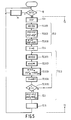
- a restoration process 72 is performed. It comprises a reference sub-picture defining step 72.1 in which the erroneous picture elements and the correct picture elements together constituting a reference sub-picture RSP are transferred from the input picture memory 7(0) to a working memory of the processor PR. This working memory then comprises, for example, the reference sub-picture RSP shown in Fig. 2. Subsequently a preset process 72.2 is performed which comprises a plurality of steps.
- a correction coefficient step 72.2(1) the correction coefficient function Q(u) indicated in expression (8) is minimized. This yields the desired correction function coefficients and hence the different correction values U(i, j) for the different picture elements of RSP.
- a difference producing step 72.2(2) the now known correction value U(i,j) is subtracted from picture element s(i.j) of RSP. This yields a difference sub-picture RSP' of difference picture elements.
- those difference picture elements located at the locations corresponding to the erroneous picture elements are set to zero in a step 72.2(3). This yields a difference sub-picture RSP o .
- an intermediate step 72.4 the value of zero is allocated to a count H and subsequently the difference sub-picture RSP is subjected to the iteration prediction process 72.3.
- This process comprises a coefficient prediction step 72.3(1) in which the prediction coefficient function Q(a) indicated in expression (6) is'minimized, starting from the difference sub-picture RSP o .
- This set is subsequently used in a picture element prediction step 72.3-(2) to determine a set of restored difference picture elements s ⁇ * (k,l) by minimizing the picture element function Q(') indicated in expression (7).
- a substitution step 72.3(3) those difference elements in the difference sub-picture RSP whose locations correspond to the erroneous picture elements in the reference sub-picture RSP are replaced by the restored difference picture elements *(k,l).
- the correction values U-(i,j), as they are known after performing correction coefficient step 72.2(1), are added in an adding step 72.4 to the picture elements of the last-obtained difference sub-picture RSP 3 .
- the restored picture elements of the reference sub-picture RSP, est with restored picture elements thus obtained are stored in adequate memory locations of the output picture memory 7(1) of the restoration circuit in a substitution step 72.5. Subsequently it is checked which error flag EF is associated with a subsequent sub-picture in input picture memory 7(0), and so forth.
- this correction function is only a rough approximation of the correction function which would have been obtained if the erroneous picture elements had been known and taken into consideration.
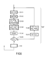
- the iteration prediction process illustrated in Fig. 6 differs from that in Fig. 5 in that in an adding step 72.3(6) a correction value U(i,j) H added to each of the difference picture elements of the difference sub-picture RSP H - 1 obtained after performing substitution step 72.3(3).
- this restored reference sub-picture RSP H is subjected to a correction coefficient step 72.3(7) in which, similarly as in step 72.2(1), the correction coefficient function Q(u) indicated in expression (8) is minimized, taking all picture elements of the restored reference sub-picture into consideration.
Priority Applications (1)
| Application Number | Priority Date | Filing Date | Title |
|---|---|---|---|
| AT89201387T ATE104102T1 (de) | 1988-06-06 | 1989-05-31 | Vorrichtung zum wiedergeben von digitalisierten bildern mittels einer fehlerwiederherstellung mit einer geneigten ebene. |
Applications Claiming Priority (2)
| Application Number | Priority Date | Filing Date | Title |
|---|---|---|---|
| NL8801440 | 1988-06-06 | ||
| NL8801440A NL8801440A (nl) | 1988-06-06 | 1988-06-06 | Inrichting voor het reproduceren van gedigitaliseerde videobeelden, met hellend vlak foutrestauratie. |
Publications (2)
| Publication Number | Publication Date |
|---|---|
| EP0345871A1 true EP0345871A1 (fr) | 1989-12-13 |
| EP0345871B1 EP0345871B1 (fr) | 1994-04-06 |
Family
ID=19852407
Family Applications (1)
| Application Number | Title | Priority Date | Filing Date |
|---|---|---|---|
| EP89201387A Expired - Lifetime EP0345871B1 (fr) | 1988-06-06 | 1989-05-31 | Dispositif pour reproduire des images vidéo numérisées avec une restauration d'erreurs à plan incliné |
Country Status (7)
| Country | Link |
|---|---|
| US (1) | US4897724A (fr) |
| EP (1) | EP0345871B1 (fr) |
| JP (1) | JP2843831B2 (fr) |
| KR (1) | KR900000885A (fr) |
| AT (1) | ATE104102T1 (fr) |
| DE (1) | DE68914330T2 (fr) |
| NL (1) | NL8801440A (fr) |
Cited By (3)
| Publication number | Priority date | Publication date | Assignee | Title |
|---|---|---|---|---|
| EP0517141A2 (fr) * | 1991-06-04 | 1992-12-09 | Kabushiki Kaisha Toshiba | Dispositif de traitement de signal à haute efficacité de codage avec réduction de l'influence de propagation d'erreurs |
| GB2286310A (en) * | 1993-11-29 | 1995-08-09 | Kokusai Electric Co Ltd | Method and apparatus for transmssion of image data |
| GB2386024B (en) * | 2000-11-28 | 2005-01-26 | Sony Electronics Inc | Robust time domain block decoding |
Families Citing this family (27)
| Publication number | Priority date | Publication date | Assignee | Title |
|---|---|---|---|---|
| JPH0722341B2 (ja) * | 1989-09-25 | 1995-03-08 | 大日本スクリーン製造株式会社 | 偽画像除去方法 |
| KR940003668B1 (ko) * | 1990-06-29 | 1994-04-25 | 삼성전자 주식회사 | 복호신호 에러 수정장치 |
| US5243428A (en) * | 1991-01-29 | 1993-09-07 | North American Philips Corporation | Method and apparatus for concealing errors in a digital television |
| WO1995003674A1 (fr) * | 1993-07-19 | 1995-02-02 | British Telecommunications Public Limited Company | Detection d'erreurs dans des images video |
| FR2751825A1 (fr) * | 1996-07-24 | 1998-01-30 | Philips Electronics Nv | Procede de filtrage temporel du bruit dans une image d'une sequence d'images numerisees et dispositif mettant en oeuvre ce procede |
| US6786420B1 (en) | 1997-07-15 | 2004-09-07 | Silverbrook Research Pty. Ltd. | Data distribution mechanism in the form of ink dots on cards |
| US6618117B2 (en) | 1997-07-12 | 2003-09-09 | Silverbrook Research Pty Ltd | Image sensing apparatus including a microcontroller |
| US6803989B2 (en) * | 1997-07-15 | 2004-10-12 | Silverbrook Research Pty Ltd | Image printing apparatus including a microcontroller |
| AUPO850597A0 (en) * | 1997-08-11 | 1997-09-04 | Silverbrook Research Pty Ltd | Image processing method and apparatus (art01a) |
| US6879341B1 (en) | 1997-07-15 | 2005-04-12 | Silverbrook Research Pty Ltd | Digital camera system containing a VLIW vector processor |
| US7110024B1 (en) | 1997-07-15 | 2006-09-19 | Silverbrook Research Pty Ltd | Digital camera system having motion deblurring means |
| US6690419B1 (en) * | 1997-07-15 | 2004-02-10 | Silverbrook Research Pty Ltd | Utilising eye detection methods for image processing in a digital image camera |
| US6948794B2 (en) * | 1997-07-15 | 2005-09-27 | Silverbrook Reserach Pty Ltd | Printhead re-capping assembly for a print and demand digital camera system |
| AUPO802797A0 (en) * | 1997-07-15 | 1997-08-07 | Silverbrook Research Pty Ltd | Image processing method and apparatus (ART54) |
| US6624848B1 (en) | 1997-07-15 | 2003-09-23 | Silverbrook Research Pty Ltd | Cascading image modification using multiple digital cameras incorporating image processing |
| US7714889B2 (en) * | 1997-07-15 | 2010-05-11 | Silverbrook Research Pty Ltd | Digital camera using exposure information for image processing |
| US6985207B2 (en) * | 1997-07-15 | 2006-01-10 | Silverbrook Research Pty Ltd | Photographic prints having magnetically recordable media |
| US7705891B2 (en) | 1997-07-15 | 2010-04-27 | Silverbrook Research Pty Ltd | Correction of distortions in digital images |
| US6820968B2 (en) * | 1997-07-15 | 2004-11-23 | Silverbrook Research Pty Ltd | Fluid-dispensing chip |
| US6476863B1 (en) * | 1997-07-15 | 2002-11-05 | Silverbrook Research Pty Ltd | Image transformation means including user interface |
| IL121521A (en) | 1997-08-11 | 2003-04-10 | Nds Ltd | Television signal glitch detector |
| AUPP702098A0 (en) | 1998-11-09 | 1998-12-03 | Silverbrook Research Pty Ltd | Image creation method and apparatus (ART73) |
| AUPQ056099A0 (en) * | 1999-05-25 | 1999-06-17 | Silverbrook Research Pty Ltd | A method and apparatus (pprint01) |
| US6404935B1 (en) * | 1999-06-02 | 2002-06-11 | Sun Microsystems, Inc. | Area efficient two-stage correction log look-up |
| US8290765B2 (en) * | 2005-03-16 | 2012-10-16 | Research In Motion Limited | Handheld electronic device with reduced keyboard and associated method of providing improved disambiguation |
| US20090228463A1 (en) * | 2008-03-10 | 2009-09-10 | Cramer Richard D | Method for Searching Compound Databases Using Topomeric Shape Descriptors and Pharmacophoric Features Identified by a Comparative Molecular Field Analysis (CoMFA) Utilizing Topomeric Alignment of Molecular Fragments |
| KR102460098B1 (ko) * | 2022-02-14 | 2022-10-28 | 주식회사 성운테크 | 플라스틱 압출생산공정에 플라스틱 입자를 신속하게 공급하기 위해서 듀얼스크린을 이용하는 플라스틱 입자 배출시스템 |
Citations (3)
| Publication number | Priority date | Publication date | Assignee | Title |
|---|---|---|---|---|
| US4189748A (en) * | 1977-08-23 | 1980-02-19 | Northrop Corporation | Video bandwidth reduction system using a two-dimensional transformation, and an adaptive filter with error correction |
| WO1987002210A1 (fr) * | 1985-10-02 | 1987-04-09 | Deutsche Thomson-Brandt Gmbh | Procede pour corriger les erreurs de transmission |
| US4703352A (en) * | 1984-12-19 | 1987-10-27 | Sony Corporation | High efficiency technique for coding a digital video signal |
Family Cites Families (4)
| Publication number | Priority date | Publication date | Assignee | Title |
|---|---|---|---|---|
| DE3028066A1 (de) * | 1980-07-24 | 1982-02-18 | Licentia Patent-Verwaltungs-Gmbh, 6000 Frankfurt | Schaltungsanordnung zur korrektur gestoerter abtastwerte bei einer pcm-uebertragungseinrichtung, insbesondere einer digital-tonplatte |
| NL8304214A (nl) * | 1983-12-07 | 1985-07-01 | Philips Nv | Werkwijze voor het korrigeren van foute waarden van monsters van een equidistant bemonsterd signaal en inrichting voor het uitvoeren van de werkwijze. |
| DE3788326T2 (de) * | 1986-09-25 | 1994-03-17 | Nec Corp | Verfahren und Apparat zur Kodierung von Bewegtbildsignalen. |
| US4785349A (en) * | 1987-10-05 | 1988-11-15 | Technology Inc. 64 | Digital video decompression system |
-
1988
- 1988-06-06 NL NL8801440A patent/NL8801440A/nl not_active Application Discontinuation
- 1988-07-20 US US07/221,692 patent/US4897724A/en not_active Expired - Lifetime
-
1989
- 1989-05-31 DE DE68914330T patent/DE68914330T2/de not_active Expired - Fee Related
- 1989-05-31 EP EP89201387A patent/EP0345871B1/fr not_active Expired - Lifetime
- 1989-05-31 AT AT89201387T patent/ATE104102T1/de not_active IP Right Cessation
- 1989-06-02 KR KR1019890007554A patent/KR900000885A/ko not_active Application Discontinuation
- 1989-06-03 JP JP1140263A patent/JP2843831B2/ja not_active Expired - Lifetime
Patent Citations (3)
| Publication number | Priority date | Publication date | Assignee | Title |
|---|---|---|---|---|
| US4189748A (en) * | 1977-08-23 | 1980-02-19 | Northrop Corporation | Video bandwidth reduction system using a two-dimensional transformation, and an adaptive filter with error correction |
| US4703352A (en) * | 1984-12-19 | 1987-10-27 | Sony Corporation | High efficiency technique for coding a digital video signal |
| WO1987002210A1 (fr) * | 1985-10-02 | 1987-04-09 | Deutsche Thomson-Brandt Gmbh | Procede pour corriger les erreurs de transmission |
Non-Patent Citations (3)
| Title |
|---|
| ELECTRONICS LETTERS, vol. 14, no. 10, 11th May 1978, pages 298-300; W. WONG et al.: "Partial correction of transmission errors in walsh transform image without recourse to error correction coding" * |
| IEEE TRANSACTIONS ON COMMUNICATIONS, vol. COM-29, no. 12, December 1981, pages 1754-1762, IEEE; O.R. MITCHELL et al.: "Channel error recovery for transform image coding" * |
| IEEE TRANSACTIONS ON COMMUNICATIONS, vol. COM-30, no. 1, January 1982, pages 257-265, IEEE, New York, US; K.N. NGAN et al.: "Enhancement of PCM and DPCM images corrupted by transmission errors" * |
Cited By (7)
| Publication number | Priority date | Publication date | Assignee | Title |
|---|---|---|---|---|
| EP0517141A2 (fr) * | 1991-06-04 | 1992-12-09 | Kabushiki Kaisha Toshiba | Dispositif de traitement de signal à haute efficacité de codage avec réduction de l'influence de propagation d'erreurs |
| EP0517141A3 (en) * | 1991-06-04 | 1993-10-20 | Toshiba Kk | High efficiency coding signal processing apparatus with error propagation influence reduction |
| US5703889A (en) * | 1991-06-04 | 1997-12-30 | Kabushiki Kaisha Toshiba | High efficiency coding signal processing apparatus with error propagation influence reduction |
| GB2286310A (en) * | 1993-11-29 | 1995-08-09 | Kokusai Electric Co Ltd | Method and apparatus for transmssion of image data |
| US5617333A (en) * | 1993-11-29 | 1997-04-01 | Kokusai Electric Co., Ltd. | Method and apparatus for transmission of image data |
| GB2286310B (en) * | 1993-11-29 | 1998-06-24 | Kokusai Electric Co Ltd | Method and apparatus for transfer of image data |
| GB2386024B (en) * | 2000-11-28 | 2005-01-26 | Sony Electronics Inc | Robust time domain block decoding |
Also Published As
| Publication number | Publication date |
|---|---|
| DE68914330T2 (de) | 1994-10-06 |
| ATE104102T1 (de) | 1994-04-15 |
| JP2843831B2 (ja) | 1999-01-06 |
| NL8801440A (nl) | 1990-01-02 |
| DE68914330D1 (de) | 1994-05-11 |
| EP0345871B1 (fr) | 1994-04-06 |
| JPH0227885A (ja) | 1990-01-30 |
| US4897724A (en) | 1990-01-30 |
| KR900000885A (ko) | 1990-01-31 |
Similar Documents
| Publication | Publication Date | Title |
|---|---|---|
| US4897724A (en) | Apparatus and method for reproducing digitized video pictures, with inclined plane error restoration | |
| US4255763A (en) | Technique for reducing transmission error propagation in an adaptively predicted DPCM video encoder | |
| US4876595A (en) | Device for reproducing digitized video pictures using an improved restoration method | |
| US4815078A (en) | Method of quantizing predictive errors | |
| US4809350A (en) | Data compression system | |
| US5751361A (en) | Method and apparatus for correcting errors in a transmitted video signal | |
| US4694336A (en) | Digital data transmission method | |
| EP0453113A1 (fr) | Appareil à coder et décoder pour données de longueur variable | |
| EP0094750B1 (fr) | Dissimulation d'erreurs dans des signaux de télévision numériques | |
| GB2092416A (en) | Method and equipment for processing gray scale facsimile signal | |
| EP0771507A1 (fr) | Procede et appareil de reduction de bruit de compression de donnees d'image | |
| EP0300775B1 (fr) | Procédé et dispositif de codage et de décodage d'un signal | |
| EP0369682B1 (fr) | Méthode de codage efficace et méthode de décodage associée | |
| EP0179560A1 (fr) | Procédé et dispositif pour le masquage d'erreurs dans des signaux de télévision numériques | |
| JPH0671237B2 (ja) | 高能率符号化方式 | |
| US4941194A (en) | Method of compressing radiation image signal | |
| JP3193437B2 (ja) | 伝送システム及び伝送システムに使用される受信機 | |
| WO1989008953A1 (fr) | Procede et appareil de transformations analogiques/numeriques/analogiques de haute resolution | |
| JP2841362B2 (ja) | 高能率符号化装置 | |
| KR100243862B1 (ko) | 전송되는 비디오 신호의 에러 은폐 방법 및 장치 | |
| US6430534B1 (en) | Method for decoding coefficients of quantization per subband using a compressed table | |
| JPH05235778A (ja) | 高能率符号化方法 | |
| JP2658094B2 (ja) | 画像情報伝送装置 | |
| KR930009187B1 (ko) | 비디오 데이타 처리방식 | |
| JP3859786B2 (ja) | 映像信号における物体の輪郭線符号化方法 |
Legal Events
| Date | Code | Title | Description |
|---|---|---|---|
| PUAI | Public reference made under article 153(3) epc to a published international application that has entered the european phase |
Free format text: ORIGINAL CODE: 0009012 |
|
| AK | Designated contracting states |
Kind code of ref document: A1 Designated state(s): AT BE CH DE ES FR GB IT LI SE |
|
| 17P | Request for examination filed |
Effective date: 19900611 |
|
| 17Q | First examination report despatched |
Effective date: 19920421 |
|
| GRAA | (expected) grant |
Free format text: ORIGINAL CODE: 0009210 |
|
| AK | Designated contracting states |
Kind code of ref document: B1 Designated state(s): AT BE CH DE ES FR GB IT LI SE |
|
| PG25 | Lapsed in a contracting state [announced via postgrant information from national office to epo] |
Ref country code: AT Effective date: 19940406 Ref country code: IT Free format text: LAPSE BECAUSE OF FAILURE TO SUBMIT A TRANSLATION OF THE DESCRIPTION OR TO PAY THE FEE WITHIN THE PRESCRIBED TIME-LIMIT;WARNING: LAPSES OF ITALIAN PATENTS WITH EFFECTIVE DATE BEFORE 2007 MAY HAVE OCCURRED AT ANY TIME BEFORE 2007. THE CORRECT EFFECTIVE DATE MAY BE DIFFERENT FROM THE ONE RECORDED. Effective date: 19940406 Ref country code: LI Effective date: 19940406 Ref country code: CH Effective date: 19940406 Ref country code: SE Free format text: THE PATENT HAS BEEN ANNULLED BY A DECISION OF A NATIONAL AUTHORITY Effective date: 19940406 Ref country code: BE Effective date: 19940406 Ref country code: ES Free format text: THE PATENT HAS BEEN ANNULLED BY A DECISION OF A NATIONAL AUTHORITY Effective date: 19940406 |
|
| REF | Corresponds to: |
Ref document number: 104102 Country of ref document: AT Date of ref document: 19940415 Kind code of ref document: T |
|
| REF | Corresponds to: |
Ref document number: 68914330 Country of ref document: DE Date of ref document: 19940511 |
|
| ET | Fr: translation filed | ||
| REG | Reference to a national code |
Ref country code: CH Ref legal event code: PL |
|
| PLBE | No opposition filed within time limit |
Free format text: ORIGINAL CODE: 0009261 |
|
| STAA | Information on the status of an ep patent application or granted ep patent |
Free format text: STATUS: NO OPPOSITION FILED WITHIN TIME LIMIT |
|
| 26N | No opposition filed | ||
| REG | Reference to a national code |
Ref country code: FR Ref legal event code: CD |
|
| REG | Reference to a national code |
Ref country code: FR Ref legal event code: CD |
|
| PGFP | Annual fee paid to national office [announced via postgrant information from national office to epo] |
Ref country code: FR Payment date: 20010523 Year of fee payment: 13 |
|
| PGFP | Annual fee paid to national office [announced via postgrant information from national office to epo] |
Ref country code: GB Payment date: 20010531 Year of fee payment: 13 |
|
| PGFP | Annual fee paid to national office [announced via postgrant information from national office to epo] |
Ref country code: DE Payment date: 20010717 Year of fee payment: 13 |
|
| REG | Reference to a national code |
Ref country code: GB Ref legal event code: IF02 |
|
| PG25 | Lapsed in a contracting state [announced via postgrant information from national office to epo] |
Ref country code: GB Free format text: LAPSE BECAUSE OF NON-PAYMENT OF DUE FEES Effective date: 20020531 |
|
| PG25 | Lapsed in a contracting state [announced via postgrant information from national office to epo] |
Ref country code: DE Free format text: LAPSE BECAUSE OF NON-PAYMENT OF DUE FEES Effective date: 20021203 |
|
| GBPC | Gb: european patent ceased through non-payment of renewal fee |
Effective date: 20020531 |
|
| PG25 | Lapsed in a contracting state [announced via postgrant information from national office to epo] |
Ref country code: FR Free format text: LAPSE BECAUSE OF NON-PAYMENT OF DUE FEES Effective date: 20030131 |
|
| REG | Reference to a national code |
Ref country code: FR Ref legal event code: ST |