EP0345525A2 - Frame, angle member for use in the frame and method of making joint portion of the angle member - Google Patents
Frame, angle member for use in the frame and method of making joint portion of the angle member Download PDFInfo
- Publication number
- EP0345525A2 EP0345525A2 EP89109258A EP89109258A EP0345525A2 EP 0345525 A2 EP0345525 A2 EP 0345525A2 EP 89109258 A EP89109258 A EP 89109258A EP 89109258 A EP89109258 A EP 89109258A EP 0345525 A2 EP0345525 A2 EP 0345525A2
- Authority
- EP
- European Patent Office
- Prior art keywords
- section
- frame
- shaped cross
- members
- inverted
- Prior art date
- Legal status (The legal status is an assumption and is not a legal conclusion. Google has not performed a legal analysis and makes no representation as to the accuracy of the status listed.)
- Withdrawn
Links
Images


Classifications
-
- B—PERFORMING OPERATIONS; TRANSPORTING
- B66—HOISTING; LIFTING; HAULING
- B66B—ELEVATORS; ESCALATORS OR MOVING WALKWAYS
- B66B23/00—Component parts of escalators or moving walkways
- B66B23/22—Balustrades
-
- E—FIXED CONSTRUCTIONS
- E04—BUILDING
- E04B—GENERAL BUILDING CONSTRUCTIONS; WALLS, e.g. PARTITIONS; ROOFS; FLOORS; CEILINGS; INSULATION OR OTHER PROTECTION OF BUILDINGS
- E04B1/00—Constructions in general; Structures which are not restricted either to walls, e.g. partitions, or floors or ceilings or roofs
- E04B1/18—Structures comprising elongated load-supporting parts, e.g. columns, girders, skeletons
- E04B1/24—Structures comprising elongated load-supporting parts, e.g. columns, girders, skeletons the supporting parts consisting of metal
- E04B1/2403—Connection details of the elongated load-supporting parts
-
- B—PERFORMING OPERATIONS; TRANSPORTING
- B66—HOISTING; LIFTING; HAULING
- B66B—ELEVATORS; ESCALATORS OR MOVING WALKWAYS
- B66B23/00—Component parts of escalators or moving walkways
- B66B23/02—Driving gear
-
- E—FIXED CONSTRUCTIONS
- E04—BUILDING
- E04B—GENERAL BUILDING CONSTRUCTIONS; WALLS, e.g. PARTITIONS; ROOFS; FLOORS; CEILINGS; INSULATION OR OTHER PROTECTION OF BUILDINGS
- E04B1/00—Constructions in general; Structures which are not restricted either to walls, e.g. partitions, or floors or ceilings or roofs
- E04B1/18—Structures comprising elongated load-supporting parts, e.g. columns, girders, skeletons
- E04B1/24—Structures comprising elongated load-supporting parts, e.g. columns, girders, skeletons the supporting parts consisting of metal
- E04B1/2403—Connection details of the elongated load-supporting parts
- E04B2001/2415—Brackets, gussets, joining plates
-
- E—FIXED CONSTRUCTIONS
- E04—BUILDING
- E04B—GENERAL BUILDING CONSTRUCTIONS; WALLS, e.g. PARTITIONS; ROOFS; FLOORS; CEILINGS; INSULATION OR OTHER PROTECTION OF BUILDINGS
- E04B1/00—Constructions in general; Structures which are not restricted either to walls, e.g. partitions, or floors or ceilings or roofs
- E04B1/18—Structures comprising elongated load-supporting parts, e.g. columns, girders, skeletons
- E04B1/24—Structures comprising elongated load-supporting parts, e.g. columns, girders, skeletons the supporting parts consisting of metal
- E04B2001/2466—Details of the elongated load-supporting parts
- E04B2001/2472—Elongated load-supporting part formed from a number of parallel profiles
-
- Y—GENERAL TAGGING OF NEW TECHNOLOGICAL DEVELOPMENTS; GENERAL TAGGING OF CROSS-SECTIONAL TECHNOLOGIES SPANNING OVER SEVERAL SECTIONS OF THE IPC; TECHNICAL SUBJECTS COVERED BY FORMER USPC CROSS-REFERENCE ART COLLECTIONS [XRACs] AND DIGESTS
- Y10—TECHNICAL SUBJECTS COVERED BY FORMER USPC
- Y10T—TECHNICAL SUBJECTS COVERED BY FORMER US CLASSIFICATION
- Y10T403/00—Joints and connections
- Y10T403/65—Scarf
Definitions
- the present invention relates to a frame for use as a main frame of an escalator, for example, to an angle member for use in the frame and to a method of making a joint portion of the angle member.
- the upper and lower members of the conventional frame are each formed by a plurality of parts connected in series in the longitudinal direction of the frame.
- Each connection is formed by a coupling member of the same L-shaped cross section bridging adjacent end portions of adjacent pair of parts of the upper or lower member and secured to the adjacent ends by bolts.
- the coupling members and the bolts of the respective connections project beyond the horizontal and vertical dimensions of the cross-sections of the upper and lower frame members to inconveniently increase the dimension of the frame. Even if the dimensional increase of the frame is slight in amount, such a slight dimensional increase causes a serious problem in the installation of an escalator because such a slight dimensional increase requires a greatly increased installation space.
- a vertical web is removed from an end portion of a length of an angle member of an L-shaped or inverted L-shaped cross section to leave a horizontal web in the end portion. Then, another web is secured by welding to the horizontal web of the end portion such that the other web is offset from the position of the vertical web thus removed toward the center of the width of the horizontal web to cooperate therewith to form a joint portion of an inverted T-shaped cross section or T-shaped cross-section.
- the frame according to the present invention includes upper and lower members respectively formed by two such angle members and connecting members interconnecting the upper and lower members.
- the upper and lower members of the frame therefore, have joint portions each of a T-shaped or inverted T-shaped cross section.
- Two such frames are connected together by coupling members respectively placed to bridge vertical webs of adjacent T-shaped or inverted T-shaped joint portions of upper and lower members and secured to the vertical webs by fastening members.
- each coupling member is each placed on side faces of the vertical webs of adjacent joint portions of lengths of angle members. Accordingly, each coupling member can be disposed within the dimension of the vertical and horizontal webs at an associated joint portion, as a result that the fastening members can also be placed as within the dimensions of the webs as possible to advantageously assure that the horizontal and vertical dimensions of each connection can be substantially equal to the dimensions of the horizontal web and the vertical web of associated joint potions.
- the horizontal web of inverted T-shaped cross section or T-shaped cross section of the joint portion of each angle member of L-shaped cross section is integral and continuous with the horizontal web of an adjacent portion of the angle member. This fact is combined with the welding of the other vertical web to the horizontal web of the joint portion along the entire length thereof to assure that the joint portion is provided with a sufficient mechanical strength.
- a main frame of an escalator is mounted to extend between upper and lower floors F.U. and F.L. of a building and supports steps (not shown) and handrails one of which is shown by 6.
- the escalator frame is composed of a pair of right and left side frames 1 and lateral connecting members 7 interconnecting the side frames.
- Each side frame 1 includes upper and lower members 2 and 3 extending longitudinally of the side frame 1 in parallel relationship with each other and connected one to the other by vertical connecting members which include perpendicular connecting members 4 each intersecting the upper and lower members 2 and 3 substantially at right angles and inclined connecting members 5 each inclined relative to the upper and lower members 2 and 3.
- the vertical connecting members 4 and 5 cooperate with the upper and lower members 2 and 3 to form a truss structure.
- the upper member 2 is formed by an angle member of an inverted L-shaped cross section having a horizontal web 2H and a vertical web 2V extending from one end of the width of the horizontal web 2H.
- the lower member 3 is also formed by an angle member of an L-shaped cross section having a horizontal web 3H and a vertical web 3V extending upwardly from one end of the width of the horizontal web 3H.
- the upper and lower members 2 and 3 are arranged such that the horizontal webs 2H and 3H extend in the same direction.
- the right and left side frames 1 are arranged such that the horizontal webs 2H extend towards each other and the horizontal webs 3H extend towards each other.
- the escalator main frame of the described structure is divided into a plurality of sections to facilitate transportation and carriage into the building.
- the divided sections have divided upper and lower members 2A and 2B and 3A and 3B and are assembled and connected with each other at an installation site.
- the adjacent ends of the divided upper and lower members 2A, 2B, 3A and 3B of the divided sections of the main frame are provided with joint portions.
- the structural details of such joint portions will be described with reference to Figs. 9 and 10 which show, as an example, the joint portions J of the divided upper member 2B of a divided main frame section.
- the vertical web 2V of the divided upper member 2B is cut away and replaced by another vertical web 9 which is laterally offset from the vertical web 2V towards the center of the width of the horizontal web 2H and secured thereto by welding W to cooperate with the horizontal web 2H to form a T-shaped cross-section.
- This vertical web 9 is formed of an elongated and rectangular plate of a thickness substantially the same as that of the vertical web 2V and bent at one end of the length of the plate to form a slope 9S which is also welded at its free end to the cut end of the vertical web 2V.
- the divided upper member 2A and the divided lower members 3A and 3B are also provided with similar joint portions J.
- the vertical webs 9 of the joint portions J of the divided upper and lower members 2A and 3A and 2B and 3B of adjacent pair of divided sections of the escalator frame are connected together by perpendicular connecting members 4, respectively.
- a pair of coupling members 8 each formed by an elongated rectangular plate are disposed to bridge adjacent ends of the vertical webs 9 of the joint portions J of the upper and lower members 2A and 2B and 3A and 3B, respectively, as shown in Fig. 2.
- the coupling members 8 are then secured to the vertical webs 9 of the upper and lower members 2A and 2B and 3A and 3B by bolts to connect the upper and lower pairs of the upper and lower members, respectively.
- the vertical webs 9 and the coupling members 8 are formed therein with bolt holes 9H and 8H for reamer bolts, respectively, to assure that the divided frame sections when connected together are aligned with each other in the longitudinal direction thereof.
- the coupling members 8 are disposed on those sides of the vertical webs 9 of the joint portions J of the upper and lower members 2 and 3 which are adjacent to the parts of the horizontal webs 2H and 3H which provide longer dimensions from the vertical webs 9 to side edges of the horizontal webs 2H and 3H.
- Reamer bolts 10 extend through the bolt holes 8H and 9H in the coupling members 8 and the vertical webs 9. Nuts 11 are threaded onto the bolts 10 and tightened against the vertical webs 9 with washers 12 interposed between the nuts and the vertical webs.
- the reamer bolts 10 have longitudinal dimensions which are substantially the same as the widthwise dimensions of the horizontal webs 2H and 3H of the upper and lower members.
- the thickness of each of the coupling members 8 is substantially equal to the widthwise dimension of the horizontal web 2H or 3H minus the total of the axial dimension of the head of each reamer bolt 10, the axial dimension of the nut 11, the thickness of the washer 12 and the thickness of the vertical web 9.
- the adjacent pair of divided frame sections are further connected by an inclined connecting member 5 which is connected at one end to the vertical web 9 of the upper member 2A of one of the divided frame sections by a reamer bolt (not shown) and at the other end to the vertical web 9 of the lower member 3B of the other divided frame section by a reamer bolt (not shown) to complete the connection between the adjacent pair of divided frame sections.
- the coupling members which connect divided sections of each side frame 1 do not extend beyond the widthwise or lateral dimensions of the upper and lower members 2 and 3 to advantageously reduce the widthwise dimension of the main frame of an escalator to assure that the space for the installation of the escalator can be decreased.
- the horizontal webs 2H and 3H of the upper and lower members 2 and 3, including the joint portions J, are each of a seamless unitary structure and, in addition, the vertical webs 9 are welded to the horizontal webs 2H and 3H along the entire lengths of the joint portions J of the webs 2H and 3H to assure a sufficient mechanical strengths of the joint portions J.
- an angle member of an L-shaped cross section with a joint portion by welding an angle member of an inverted T-shaped (or T-shaped) cross section to an end of the L-shaped angle member.
- the welding is conducted only between the horizontal web of the L-shaped angle member and the horizontal web of the inverted T cross section angle member. Accordingly, the structure of the joint portion prepared according to the present invention provides an increased mechanical strength to improve the reliability.
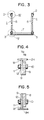
- the spacing between a neutral axis X8 of each coupling member 8 and a neutral axis 9X of an inverted T-shaped cross section formed by an associated horizontal web 2H and the vertical web 9 welded thereto, as shown in Fig. 4, is smaller than such spacing in the conventional joint portion to reduce the bending moment which acts on an associated reamer bolt 10.
- the component parts for connecting the divided frame sections such as coupling members 8, bolts 10, nuts 11 and washers 12, are so arranged as not to project beyond the dimensions of the horizontal webs 2H and 3H of the upper and lower members 2 and 3. It will be allowable in some cases that such connecting component parts project to a certain extent beyond the dimensions of the webs 2H and 3H.
- the tightening faces of the bolts 10 and nuts 11, i.e., the inwardly directed faces of the bolts 10 and nuts 11 which abut against the coupling member 8 and against the washers 12, should be disposed within the dimensions of the horizontal webs 2H and 3H so as to assure a reduction in the dimensions of the escalator side frames 1 measured laterally thereof, i.e., axially of the nuts.
- the present invention provides a frame in which the joint portions of the upper member of inverted L-shaped cross-sections and the joint portions of the lower members of L-shaped cross-sections are connected respectively by coupling members having dimensions, as measured laterally of the frame, which are substantially equal to te dimensions of the horizontal and vertical webs of the upper and lower members.
- the method of the present invention can provide an angle member with a joint portion having an improved mechanical strength.
Landscapes
- Engineering & Computer Science (AREA)
- Architecture (AREA)
- Physics & Mathematics (AREA)
- Electromagnetism (AREA)
- Civil Engineering (AREA)
- Structural Engineering (AREA)
- Escalators And Moving Walkways (AREA)
- Mutual Connection Of Rods And Tubes (AREA)
- Joining Of Building Structures In Genera (AREA)
Abstract
A frame (1) has elongated upper and lower angle members (2, 3) each comprising two parts (2A, 2B; 3A, 3B) both having L-shaped cross sections and joint portions (J) of T-shaped cross sections formed at adjacent end portions of the two parts. The legs (9) of the T-shaped joint portions (J) are connected by a coupling member (8) disposed on the legs and secured thereto by fastening members (10, 11).
Description
- The present invention relates to a frame for use as a main frame of an escalator, for example, to an angle member for use in the frame and to a method of making a joint portion of the angle member.
- In the conventional frame of the class specified above, upper and lower members both having L-shaped cross-sections are connected by connecting members, as disclosed in Japanese Unexamined Patent Publication No. 54-31187 and Japanese Unexamined Utility Model Publication No. 53-39990.
- The upper and lower members of the conventional frame are each formed by a plurality of parts connected in series in the longitudinal direction of the frame. Each connection is formed by a coupling member of the same L-shaped cross section bridging adjacent end portions of adjacent pair of parts of the upper or lower member and secured to the adjacent ends by bolts. Thus, the coupling members and the bolts of the respective connections project beyond the horizontal and vertical dimensions of the cross-sections of the upper and lower frame members to inconveniently increase the dimension of the frame. Even if the dimensional increase of the frame is slight in amount, such a slight dimensional increase causes a serious problem in the installation of an escalator because such a slight dimensional increase requires a greatly increased installation space.
- It is an object of the present invention to provide a frame in which the horizontal and vertical dimensions of connections between adjacent pairs of parts of upper and lower frame members of an L-shaped or inverted L-shaped cross section are substantially equal to those of the cross-sections of the upper and lower members, respectively.
- It is another object of the present invention to provide an angle member having a joint portion of a widthwise dimension which falls within that of the horizontal web of the angle member.
- It is a further object of the present invention to provide a method of making at an end of an angle member a joint portion of the class specified in the preceding paragraph.
- According to the present invention, a vertical web is removed from an end portion of a length of an angle member of an L-shaped or inverted L-shaped cross section to leave a horizontal web in the end portion. Then, another web is secured by welding to the horizontal web of the end portion such that the other web is offset from the position of the vertical web thus removed toward the center of the width of the horizontal web to cooperate therewith to form a joint portion of an inverted T-shaped cross section or T-shaped cross-section.
- The frame according to the present invention includes upper and lower members respectively formed by two such angle members and connecting members interconnecting the upper and lower members. The upper and lower members of the frame, therefore, have joint portions each of a T-shaped or inverted T-shaped cross section. Two such frames are connected together by coupling members respectively placed to bridge vertical webs of adjacent T-shaped or inverted T-shaped joint portions of upper and lower members and secured to the vertical webs by fastening members.
- The coupling members are each placed on side faces of the vertical webs of adjacent joint portions of lengths of angle members. Accordingly, each coupling member can be disposed within the dimension of the vertical and horizontal webs at an associated joint portion, as a result that the fastening members can also be placed as within the dimensions of the webs as possible to advantageously assure that the horizontal and vertical dimensions of each connection can be substantially equal to the dimensions of the horizontal web and the vertical web of associated joint potions.
- The horizontal web of inverted T-shaped cross section or T-shaped cross section of the joint portion of each angle member of L-shaped cross section is integral and continuous with the horizontal web of an adjacent portion of the angle member. This fact is combined with the welding of the other vertical web to the horizontal web of the joint portion along the entire length thereof to assure that the joint portion is provided with a sufficient mechanical strength.
- The above and other objects, features and advantages of the present invention will be made more apparent by the following description with reference to the accompanying drawings.
-
- Fig. 1 is a side elevational view of a main frame of an escalator embodying the present invention;
- Fig. 2 is an enlarged side view of the portion of the main frame indicated by a circle II in Fig. 1;
- Fig. 3 is an enlarged cross-sectional view of the main frame taken along line III-III in Fig. 2;
- Fig. 4 is an enlarged view of the portion of the main frame indicated by a circle IV in Fig. 3;
- Fig. 5 is an enlarged view of the portion of the main frame indicated by a circle V in Fig. 3;
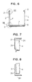
- Fig. 6 is an enlarged cross-sectional view of the main frame taken along line VI-VI in Fig. 1;
- Fig. 7 is an enlarged view of the portion of the main frame indicated by a circle VII in Fig. 6;
- Fig. 8 is an enlarged view of the portion of the main frame indicated by a circle VIII in Fig. 6;
- Fig. 9 is an enlarged view of the portion of the main frame indicated by an oval circle IX in Fig. 2; and
- Fig. 10 is a perspective view of a joint between angle members according to the present invention.
- An embodiment of the present invention will be described with reference to Figs. 1 - 10 of the drawings. A main frame of an escalator is mounted to extend between upper and lower floors F.U. and F.L. of a building and supports steps (not shown) and handrails one of which is shown by 6. The escalator frame is composed of a pair of right and
left side frames 1 and lateral connectingmembers 7 interconnecting the side frames. Eachside frame 1 includes upper andlower members side frame 1 in parallel relationship with each other and connected one to the other by vertical connecting members which include perpendicular connectingmembers 4 each intersecting the upper andlower members members 5 each inclined relative to the upper andlower members members lower members upper member 2 is formed by an angle member of an inverted L-shaped cross section having ahorizontal web 2H and avertical web 2V extending from one end of the width of thehorizontal web 2H. Thelower member 3 is also formed by an angle member of an L-shaped cross section having ahorizontal web 3H and avertical web 3V extending upwardly from one end of the width of thehorizontal web 3H. The upper andlower members horizontal webs left side frames 1 are arranged such that thehorizontal webs 2H extend towards each other and thehorizontal webs 3H extend towards each other. - The escalator main frame of the described structure is divided into a plurality of sections to facilitate transportation and carriage into the building. The divided sections have divided upper and
lower members lower members upper member 2B of a divided main frame section. Within the range of the joint portion J, thevertical web 2V of the dividedupper member 2B is cut away and replaced by another vertical web 9 which is laterally offset from thevertical web 2V towards the center of the width of thehorizontal web 2H and secured thereto by welding W to cooperate with thehorizontal web 2H to form a T-shaped cross-section. This vertical web 9 is formed of an elongated and rectangular plate of a thickness substantially the same as that of thevertical web 2V and bent at one end of the length of the plate to form aslope 9S which is also welded at its free end to the cut end of thevertical web 2V. - The divided
upper member 2A and the dividedlower members lower members members 4, respectively. - When an adjacent pair of divided sections of the escalator frame are connected together, a pair of
coupling members 8 each formed by an elongated rectangular plate are disposed to bridge adjacent ends of the vertical webs 9 of the joint portions J of the upper andlower members coupling members 8 are then secured to the vertical webs 9 of the upper andlower members coupling members 8 are formed therein withbolt holes 9H and 8H for reamer bolts, respectively, to assure that the divided frame sections when connected together are aligned with each other in the longitudinal direction thereof. Thecoupling members 8 are disposed on those sides of the vertical webs 9 of the joint portions J of the upper andlower members horizontal webs horizontal webs Reamer bolts 10 extend through thebolt holes 8H and 9H in thecoupling members 8 and the vertical webs 9. Nuts 11 are threaded onto thebolts 10 and tightened against the vertical webs 9 withwashers 12 interposed between the nuts and the vertical webs. - The
reamer bolts 10 have longitudinal dimensions which are substantially the same as the widthwise dimensions of thehorizontal webs coupling members 8 is substantially equal to the widthwise dimension of thehorizontal web reamer bolt 10, the axial dimension of the nut 11, the thickness of thewasher 12 and the thickness of the vertical web 9. - When the connections between the divided
upper members lower members member 5 which is connected at one end to the vertical web 9 of theupper member 2A of one of the divided frame sections by a reamer bolt (not shown) and at the other end to the vertical web 9 of thelower member 3B of the other divided frame section by a reamer bolt (not shown) to complete the connection between the adjacent pair of divided frame sections. - According to the embodiment of the invention described above, the coupling members which connect divided sections of each
side frame 1 do not extend beyond the widthwise or lateral dimensions of the upper andlower members horizontal webs lower members horizontal webs webs - It would be possible to provide an angle member of an L-shaped cross section with a joint portion by welding an angle member of an inverted T-shaped (or T-shaped) cross section to an end of the L-shaped angle member. In this case, however, the welding is conducted only between the horizontal web of the L-shaped angle member and the horizontal web of the inverted T cross section angle member. Accordingly, the structure of the joint portion prepared according to the present invention provides an increased mechanical strength to improve the reliability.
- Moreover, according to the structure of the joint portion J of the invention, the spacing between a neutral axis X8 of each
coupling member 8 and a neutral axis 9X of an inverted T-shaped cross section formed by an associatedhorizontal web 2H and the vertical web 9 welded thereto, as shown in Fig. 4, is smaller than such spacing in the conventional joint portion to reduce the bending moment which acts on an associatedreamer bolt 10. - In the described and illustrated embodiment of the invention, moreover, the component parts for connecting the divided frame sections, such as
coupling members 8,bolts 10, nuts 11 andwashers 12, are so arranged as not to project beyond the dimensions of thehorizontal webs lower members webs bolts 10 and nuts 11, i.e., the inwardly directed faces of thebolts 10 and nuts 11 which abut against thecoupling member 8 and against thewashers 12, should be disposed within the dimensions of thehorizontal webs - As will be understood from the foregoing description, the present invention provides a frame in which the joint portions of the upper member of inverted L-shaped cross-sections and the joint portions of the lower members of L-shaped cross-sections are connected respectively by coupling members having dimensions, as measured laterally of the frame, which are substantially equal to te dimensions of the horizontal and vertical webs of the upper and lower members.
- In addition, the method of the present invention can provide an angle member with a joint portion having an improved mechanical strength.
Claims (14)
1. A frame (1) including at least two frame sections each comprising upper and lower members (2A, 3A or 2B, 3B) extending longitudinally of said frame and in parallel with each other and connecting members (4, 5) interconnecting said upper and lower members, said upper member having a substantially inverted L-shaped cross section, said lower member having a substantially L-shaped cross section, each of said upper and lower members of each frame section including a joint portion (J), said frame further including means (8, 10, 11) for coupling the joint portions of said upper and lower members of said frame sections together, wherein the joint portion (J) of said upper member (2A or 2B) of each frame section has a substantially T-shaped cross section, the joint portion (J) of said lower member (3A or 3B) of each frame section has a substantially inverted T-shaped cross section and wherein said coupling means comprise elongated and rectangular coupling members (8) respectively attached to side faces of vertical webs (9) of the T-shaped joint portions (J) of the upper members (2A or 2B) of said frame sections and to side faces of vertical webs (9) of the inverted T-shaped joint portions (J) of said lower members (3A or 3B) of said frame sections, and means (10, 11) for fastening said coupling members (8) to associated vertical webs (9).
2. A frame according to claim 1, wherein said coupling members (8) each comprise a plate member.
3. A frame according to Claim 1 or 2, wherein the vertical webs (9) of said T-shaped and inverted T-shaped joint portions (J) are offset from centers of widths of horizontal webs (2H, 3H) of said T-shaped and inverted T-shaped joint portions, respectively, and said coupling members (8) are attached to those side faces of said vertical webs (9) which are nearer to the widthwise centers of said horizontal webs (2H, 3H).
4. A frame according to any of claims 1 to 3, wherein thc horizontal webs (2H and 3H) of said T-shaped cross section and inverted T-shaped cross section have widthwise and thicknesswise dimensions equal to those of said inverted L-shaped cross section and said L-shaped cross section, respectively.
5. A frame according to Claim 4, wherein said fastening means comprises bolts, preferably reamer bolts.
6. A frame according to any of claims 1 to 5, wherein said inverted L-shaped cross section and L-shaped cross section of said upper and lower members (2, 3) have vertical webs (2V, 3V) respectively connected to the vertical webs (9) of said T-shaped cross section and said inverted T-shaped cross section.
7. A frame (1) comprising upper and lower members (2A or 2B; 3A or 3B) extending longitudinally of said frame and in parallel with each other, said upper member having a substantially inverted L-shaped cross section, said lower member having a substantially L-shaped cross section, wherein said upper member has an end formed into a joint portion (J) of a substantially T-shaped cross section and said lower member has an end formed into a joint portion (J) of a substantially inverted T-shaped cross section.
8. A frame (1) including at least two frame sections each comprising upper and lower members (2A, 3A or 2B, 3B) extending longitudinally of said frame and in parallel with each other and connecting members (4, 5) interconnecting said upper and lower members, said upper member having a substantially inverted L-shaped cross section, said lower member having a substantially L-shaped cross section, each of said upper and lower members of each frame section including a joint portion (J), said frame further including means (8, 10, 11) for coupling the joint portions of said upper and lower members of said frame sections together, wherein the joint portion (J) of said upper member (2A or 2B) of each frame section has a substantially T-shaped cross section, the joint portion (J) of said lower member (3A or 3B) of each frame section has a substantially inverted T-shaped cross section, wherein said coupling means comprise coupling members (8) respectively attached to side faces of vertical webs (9) of the T-shaped joint portions (J) of the upper members (2A or 2B) of said frame sections and to side faces of vertical webs (9) of the inverted T-shaped joint portions (J) of said lower members (3A or 3B) of said frame sections, and means (10, 11) for fastening said coupling members (8) to associated vertical webs (9), and wherein said fastening means have fastening faces disposed within the dimensions of the horizontal webs (2H, 3H) of said T-shaped and inverted T-shaped cross sections.
9. A frame (1) including at least two frame sections each comprising upper and lower members (2A, 3A or 2B, 3B) extending longitudinally of said frame and in parallel with each other and connecting members (4, 5) interconnecting said upper and lower members, said upper member having a substantially inverted L-shaped cross section, said lower member having a substantially L-shaped cross section, each of said upper and lower members of each frame section including a joint portion (J), said frame further including means (8, 10, 11) for coupling the joint portions of said upper and lower members of said frame sections together, wherein the joint portion (J) of said upper member (2A or 2B) of each frame section has a substantially T-shaped cross section, the joint portion (J) of said lower member (3A or 3B) of each frame section has a substantially inverted T-shaped cross section, wherein said coupling means comprise coupling members (8) respectively attached to side faces of vertical webs (9) of the T-shaped joint portions (J) of the upper members (2A or 2B) of said frame sections and to side faces of vertical webs (9) of the inverted T-shaped joint portions (J) of said lower members (3A or 3B) of said frame sections, and means (10, 11) for fastening said coupling members (8) to associated vertical webs (9), and wherein each of said coupling members (8) and associated fastening means are disposed within the dimensions of the horizontal webs (2H, 3H) of said T-shaped and inverted T-shaped cross sections.
10. A frame structure for a passenger conveyor, comprising a pair of laterally spaced side frames (1) each including at least two frame sections each comprising upper and lower members (2A, 3A or 2B, 3B) extending longitudinally of said frame and in parallel with each other and vertical connecting members (4, 5) interconnecting said upper and lower members, said upper member having a substantially inverted L-shaped cross section, said lower member having a substantially L-shaped cross section, each of said upper and lower members of each frame section including a joint portion (J), said frame further including means (8, 10, 11) for coupling the joint portions of said upper and lower members of said frame sections together, said side frames being arranged such that horizontal webs (2H, 3H) of said inverted L-shaped cross section and L-shaped cross-section are directed inwardly, said frame structure further including lateral connecting members (7) interconnecting said side frames (1), wherein the joint portion (J) of said upper member (2A or 2B) of each frame section has a sub stantially T-shaped cross section, the joint portion (J) of said lower member (3A or 3B) of each frame section has a substantially inverted T-shaped cross section and wherein said coupling means comprise coupling members (8) each formed of a plate and respectively attached to inner side faces of vertical webs (9) of the T-shaped joint portions (J) of the upper members (2A or 2B) of said frame sections and to inner side faces of vertical webs (9) of the inverted T-shaped joint portions (J) of said lower members (3A or 3B) of said frame sections, and reamer bolts (10) for fastening said coupling members (8) to associated vertical webs (9).
11. An angle member (2, 3) for a frame structure, having an end formed into a joint portion (J) of an inverted T-shaped cross section.
12. A method of making a joint portion (J) of a substantially inverted T-shaped cross section at an end portion of a length of an angle member (3) of a substantially L-shaped cross section formed by a horizontal web (3H) and a vertical web (3V), comprising the steps of:
removing said vertical web (3V) from said angle member at said end portion to leave said horizontal web (3H) at said end portion; and
securing, by welding, another web (9) to said horizontal web (3H) at said end portion of said angle member such that said other web is offset from the position of said vertical web (3V) thus removed toward the center of the width of said horizontal web (3H) to cooperate therewith to form the substantially inverted T-shaped cross section.
removing said vertical web (3V) from said angle member at said end portion to leave said horizontal web (3H) at said end portion; and
securing, by welding, another web (9) to said horizontal web (3H) at said end portion of said angle member such that said other web is offset from the position of said vertical web (3V) thus removed toward the center of the width of said horizontal web (3H) to cooperate therewith to form the substantially inverted T-shaped cross section.
13. A method according to Claim 12, further including the step of securing, by welding, said other web (9) to the vertical web (3V) left on said angle member excepting at said end portion thereof.
14. An elongated structural member (8) for a frame (1), said member comprising at least two parts (3A, 3B) both having a substantially L-shaped cross section and joint portions (J) both of substantially inverted T-shaped cross sections formed at adjacent ends of said two parts, a coupling member (9) disposed in contact with legs (9) of said inverted T-shaped cross sections of said joint portions, and means (10, 11) for fastening said coupling member (8) to said legs (9) of said inverted T-shaped cross sections to connect said two parts (3A, 3B) together.
Applications Claiming Priority (2)
| Application Number | Priority Date | Filing Date | Title |
|---|---|---|---|
| JP137556/88 | 1988-06-06 | ||
| JP63137556A JPH0735236B2 (en) | 1988-06-06 | 1988-06-06 | Frame for passenger conveyor |
Publications (2)
| Publication Number | Publication Date |
|---|---|
| EP0345525A2 true EP0345525A2 (en) | 1989-12-13 |
| EP0345525A3 EP0345525A3 (en) | 1992-04-29 |
Family
ID=15201479
Family Applications (1)
| Application Number | Title | Priority Date | Filing Date |
|---|---|---|---|
| EP19890109258 Withdrawn EP0345525A3 (en) | 1988-06-06 | 1989-05-23 | Frame, angle member for use in the frame and method of making joint portion of the angle member |
Country Status (5)
| Country | Link |
|---|---|
| US (1) | US4958473A (en) |
| EP (1) | EP0345525A3 (en) |
| JP (1) | JPH0735236B2 (en) |
| KR (1) | KR910000513A (en) |
| CN (1) | CN1018173B (en) |
Cited By (2)
| Publication number | Priority date | Publication date | Assignee | Title |
|---|---|---|---|---|
| WO2020173753A2 (en) | 2019-02-27 | 2020-09-03 | Inventio Ag | Truss section connection region |
| EP4353655A1 (en) * | 2022-10-10 | 2024-04-17 | TK Elevator Innovation and Operations GmbH | Modular track device with a molded/performance module connection and method and use |
Families Citing this family (19)
| Publication number | Priority date | Publication date | Assignee | Title |
|---|---|---|---|---|
| KR100358495B1 (en) * | 1999-11-26 | 2002-10-30 | 엘지 오티스 엘리베이터 유한회사 | Compensation of rail length moving board |
| US20020175039A1 (en) * | 2001-05-11 | 2002-11-28 | Fargo Richard N. | Escalator support structure |
| US20050108974A1 (en) * | 2003-11-21 | 2005-05-26 | Richard Lauch | Escalator solid side truss construction |
| ES2299408B1 (en) * | 2007-10-18 | 2009-06-12 | Thyssenkrupp Elevator (Es/Pbb) Ltd. | SELF-SUPPORTING GUIDE SYSTEM FOR ROLLING CORRIDORS. |
| CN101955121B (en) * | 2010-04-29 | 2012-11-14 | 江南嘉捷电梯股份有限公司 | Adjusting structure of intermediate supports on escalator or moving walk |
| CN101955123A (en) * | 2010-04-29 | 2011-01-26 | 江南嘉捷电梯股份有限公司 | Angle steel splicing structure of main girder on escalator or moving sidewalk |
| WO2011141945A1 (en) * | 2010-05-10 | 2011-11-17 | 株式会社 日立製作所 | Passenger conveyor |
| CN101934965A (en) * | 2010-07-30 | 2011-01-05 | 江南嘉捷电梯股份有限公司 | Main girder square steel splicing structure on escalator or moving pavement |
| CN104355213A (en) * | 2014-11-06 | 2015-02-18 | 康力电梯股份有限公司 | Truss reinforcing device |
| EP3150539A1 (en) * | 2015-09-29 | 2017-04-05 | Inventio AG | Supporting structure for a person transport installation |
| EP3150540A1 (en) * | 2015-09-29 | 2017-04-05 | Inventio AG | Method of manufacturing a support structure for a person transport installation |
| EP3356277B1 (en) * | 2015-09-29 | 2019-07-31 | Inventio AG | Method for mounting a bearing structure for a person transport installation in a building structure |
| CN105257031A (en) * | 2015-11-11 | 2016-01-20 | 太重(天津)重型装备科技开发有限公司 | Belt conveyor corridor system |
| CN106948548A (en) * | 2017-04-26 | 2017-07-14 | 广西大学 | A kind of precast concrete frame beam structure |
| CN108059054B (en) * | 2017-12-14 | 2023-07-04 | 山东博尔特电梯有限公司 | Steel structure of elevator derrick and installation method thereof |
| CN108557622A (en) * | 2018-06-29 | 2018-09-21 | 重庆迈高电梯有限公司 | A kind of moving staircase girders |
| JP2021116832A (en) * | 2020-01-23 | 2021-08-10 | 日本製鉄株式会社 | High-power bolt friction joint structure |
| CN111824917A (en) * | 2020-07-07 | 2020-10-27 | 日立电梯(广州)自动扶梯有限公司 | Connection structure and method of manufacture, truss and escalator or moving walk |
| CN111646351A (en) * | 2020-07-20 | 2020-09-11 | 通力电梯有限公司 | Joint assembly of truss bottom plate and escalator or automatic pedestrian path truss |
Family Cites Families (10)
| Publication number | Priority date | Publication date | Assignee | Title |
|---|---|---|---|---|
| US2058537A (en) * | 1933-03-16 | 1936-10-27 | Walter H Weiskopf | Structural beam |
| US3078970A (en) * | 1959-10-05 | 1963-02-26 | Robert S Black | Truss-type adjustable joist |
| US3707220A (en) * | 1970-11-23 | 1972-12-26 | Westinghouse Electric Corp | Modular passenger conveyor construction |
| JPS52137880A (en) * | 1976-05-12 | 1977-11-17 | Hitachi Ltd | Main frame for man conveyor |
| JPS5751265Y2 (en) * | 1976-09-10 | 1982-11-09 | ||
| CH621310A5 (en) * | 1977-04-19 | 1981-01-30 | Masyc Ag | |
| JPS5431187A (en) * | 1977-08-12 | 1979-03-07 | Hitachi Ltd | Main frame of man conveyor |
| JPS57107385A (en) * | 1980-12-22 | 1982-07-03 | Hitachi Ltd | Man conveyor |
| JPS5895965U (en) * | 1981-12-21 | 1983-06-29 | 三菱電機株式会社 | Passenger conveyor main frame device |
| JPS5920595A (en) * | 1982-07-26 | 1984-02-02 | Nissan Motor Co Ltd | Compressor |
-
1988
- 1988-06-06 JP JP63137556A patent/JPH0735236B2/en not_active Expired - Lifetime
-
1989
- 1989-05-23 EP EP19890109258 patent/EP0345525A3/en not_active Withdrawn
- 1989-05-31 CN CN89103803A patent/CN1018173B/en not_active Expired
- 1989-06-02 US US07/360,220 patent/US4958473A/en not_active Expired - Fee Related
- 1989-06-05 KR KR1019890007748A patent/KR910000513A/en not_active Withdrawn
Cited By (5)
| Publication number | Priority date | Publication date | Assignee | Title |
|---|---|---|---|---|
| WO2020173753A2 (en) | 2019-02-27 | 2020-09-03 | Inventio Ag | Truss section connection region |
| AU2020227162B2 (en) * | 2019-02-27 | 2023-07-13 | Inventio Ag | Truss section connection region |
| US11913215B2 (en) | 2019-02-27 | 2024-02-27 | Inventio Ag | Truss section connection region |
| EP4353655A1 (en) * | 2022-10-10 | 2024-04-17 | TK Elevator Innovation and Operations GmbH | Modular track device with a molded/performance module connection and method and use |
| WO2024078839A1 (en) | 2022-10-10 | 2024-04-18 | Tk Elevator Innovation And Operations Gmbh | Modular guideway system with a form-fitting/force-fitting module connection, method, and use |
Also Published As
| Publication number | Publication date |
|---|---|
| KR910000513A (en) | 1991-01-29 |
| EP0345525A3 (en) | 1992-04-29 |
| US4958473A (en) | 1990-09-25 |
| CN1018173B (en) | 1992-09-09 |
| JPH01308387A (en) | 1989-12-13 |
| JPH0735236B2 (en) | 1995-04-19 |
| CN1038995A (en) | 1990-01-24 |
Similar Documents
| Publication | Publication Date | Title |
|---|---|---|
| US4958473A (en) | Frame, angle member for use in the frame and method of making joint portion of the angel member | |
| US7373758B2 (en) | Seismic brace with a removable restraining member disposed around a middle portion of an elongated central brace unit | |
| JPH07116684B2 (en) | Main girder joint structure in bridges, etc. | |
| JPS6118691A (en) | Frame for escalator | |
| EP1626827A1 (en) | Construction element and a vehicle frame comprising such a construction element | |
| JP2004156291A (en) | Bridge girder structure and bridge girder erection method | |
| JP2781343B2 (en) | Scaffold board structure | |
| HU185499B (en) | Lattise truss | |
| JPS6219749Y2 (en) | ||
| JP4555868B2 (en) | Handrail | |
| JP2729444B2 (en) | Riding gantry | |
| JP7698808B1 (en) | Method for forming joint structure and joint structure | |
| CN216893433U (en) | Welding-free type walkway plate | |
| JPH1113205A (en) | Buckling stiffening members | |
| JPH082165Y2 (en) | Joint structure of sielter using deck plate | |
| JPH0220323Y2 (en) | ||
| JPS602145Y2 (en) | Structure of rail support beam | |
| GB2153480A (en) | Connector for members of a structural framework | |
| JPS6321640Y2 (en) | ||
| KR940007048Y1 (en) | Lining steel-board for temporary pavings | |
| JPH0689582B2 (en) | Reinforcing bar joint construction method | |
| JPH06173340A (en) | Steel beam joint structure | |
| JPS5929045Y2 (en) | Beam connection structure | |
| JPH04127357U (en) | Separator connection fittings | |
| GB2155085A (en) | Girder arch and the like securing member |
Legal Events
| Date | Code | Title | Description |
|---|---|---|---|
| PUAI | Public reference made under article 153(3) epc to a published international application that has entered the european phase |
Free format text: ORIGINAL CODE: 0009012 |
|
| AK | Designated contracting states |
Kind code of ref document: A2 Designated state(s): CH GB LI |
|
| 17P | Request for examination filed |
Effective date: 19901212 |
|
| PUAL | Search report despatched |
Free format text: ORIGINAL CODE: 0009013 |
|
| AK | Designated contracting states |
Kind code of ref document: A3 Designated state(s): CH GB LI |
|
| STAA | Information on the status of an ep patent application or granted ep patent |
Free format text: STATUS: THE APPLICATION IS DEEMED TO BE WITHDRAWN |
|
| 18D | Application deemed to be withdrawn |
Effective date: 19921030 |