EP0344729A1 - Method and apparatus for treating cotton fibres contaminated by honey dew - Google Patents
Method and apparatus for treating cotton fibres contaminated by honey dew Download PDFInfo
- Publication number
- EP0344729A1 EP0344729A1 EP89109777A EP89109777A EP0344729A1 EP 0344729 A1 EP0344729 A1 EP 0344729A1 EP 89109777 A EP89109777 A EP 89109777A EP 89109777 A EP89109777 A EP 89109777A EP 0344729 A1 EP0344729 A1 EP 0344729A1
- Authority
- EP
- European Patent Office
- Prior art keywords
- microwave oven
- microwave
- fleece
- flakes
- cotton
- Prior art date
- Legal status (The legal status is an assumption and is not a legal conclusion. Google has not performed a legal analysis and makes no representation as to the accuracy of the status listed.)
- Granted
Links
Images

Classifications
-
- D—TEXTILES; PAPER
- D01—NATURAL OR MAN-MADE THREADS OR FIBRES; SPINNING
- D01G—PRELIMINARY TREATMENT OF FIBRES, e.g. FOR SPINNING
- D01G99/00—Subject matter not provided for in other groups of this subclass
-
- H—ELECTRICITY
- H05—ELECTRIC TECHNIQUES NOT OTHERWISE PROVIDED FOR
- H05B—ELECTRIC HEATING; ELECTRIC LIGHT SOURCES NOT OTHERWISE PROVIDED FOR; CIRCUIT ARRANGEMENTS FOR ELECTRIC LIGHT SOURCES, IN GENERAL
- H05B6/00—Heating by electric, magnetic or electromagnetic fields
- H05B6/64—Heating using microwaves
- H05B6/78—Arrangements for continuous movement of material
Definitions
- the present invention relates to a method and a device for reducing the stickiness of the fibers of cotton flakes contaminated with honeydew by the supply of heat.
- honeydew cotton flakes from some provinces are more or less infested with sugar-containing excretions from insects. These excretions containing sugar are commonly referred to as honeydew.
- a laboratory method is known by means of which the honeydew is caramelized by heating cotton flake samples in an oven, with the aim of determining the degree of contamination with honeydew from the change in the color of the cotton flake that occurs. This is very important because the cotton flakes become sticky in the event of heavy infestation and tend to stick to different parts of the yarn production system or to form rolls on rollers or other rotatable organs, which is very undesirable since it leads to frequent interruptions in the yarn production process .
- the object of the present invention is to provide a method and a device of the type mentioned at the outset, which selectively heats the honeydew component of the contaminated flakes with reduced energy expenditure.
- the flakes in the form of a fleece fleece or a flock of cotton wool are placed on a conveyor belt and a microwave oven constructed as a tunnel is moved therein and heated in the latter by means of microwave energy.
- the invention provides that the conveyor belt provided for the transport of the cotton flakes through the microwave oven consists of a means that absorbs little energy, in particular of polypropylene, and is deflected by two deflection rollers arranged at the entrance and exit of the tunnel-like oven, one of which can be driven. and that the roof of the housing of the microwave oven is designed as an extractor hood.
- the present invention is based on the finding that the water molecules contained in sugar or honeydew are preferred in microwave radiation Vibrations are set, whereby a greater heating of the honeydew component takes place in comparison to the remaining components of the flake fleece, whereby the honeydew components are converted into the desired non-tacky state.
- This selective heating of the honeydew component significantly reduces the amount of energy required for the process compared to other warming-up processes and prevents the temperature of the cotton flakes themselves from becoming too high, so that the risk of fire, which must always be taken into account when treating cotton flakes, is significantly reduced. This also largely avoids the risk of unwanted discoloration of the cotton flakes.
- the energy supply to the cotton flakes can take place in intermittent operation, ie the conveyor belt stands still in the oven while the fiber flakes placed thereon are heated up.
- the method is preferably carried out in continuous operation, ie the heating takes place during the movement of the conveyor belt through the tunnel.
- this has the advantage that the method according to the invention can be optimally integrated into the yarn production, in which a continuous supply of the fiber flakes to the card is desired.
- the fleece experiences a constant energy density and a correspondingly metered amount of energy in the tunnel due to the continuous movement, so that the honey dew constituents are heated up particularly uniformly, thereby avoiding local heating of the fleece to temperatures that would pose a fire hazard.
- the leveling out achieved by the movement can also reduce the Energy density in the fleece eliminates any form of wave stirrer.
- the vapors escaping during the supply of heat in the microwave oven are preferably drawn off during heating, as a result of which the fleece leaves the microwave oven in the dry state.
- a particularly preferred embodiment of the method according to the invention is characterized in that the fiber flakes remain in the oven for a time in the range from 5 to 30 and in particular for about 20 seconds and with a fleece width in the range from 80 to 120 cm and fleece thickness from 5 to 15 cm, the energy supply in the range of 50-300 kJ per kg of cotton, preferably around 175 kJ per kg of cotton.
- the values given are with conventional cotton processing equipment and with microwave generators available on the market, e.g. to reach the Gigatherm company.
- microwave generators with an output power of 1.2 kW each are required, which are preferably arranged in two rows.
- Control of the energy density can not only be achieved by controlling the output energy of each microwave generator, but it can also be varied within very broad limits by switching off one or more microwave generators. It is also possible to always equip the system with more microwave generators than for the highest degree of Contamination is necessary, so that if one or the other microwave generator fails, a new generator can be put into operation, which can significantly extend the period of use of the microwave oven.
- the entire oven can be bypassed or put out of operation without this having any adverse effects on the processing of the cotton flakes. E.g. it is not necessary to make any changes to the design of the entire fiber processing system.
- the microwave oven consists of several microwave generators which can be operated at the same time or individually, these, preferably if there are 10 to 14, in particular 12, microwave generators, are preferably arranged in two rows above the conveyor belt.
- microwave generators of a width of about 40 cm available on the market to arrange them side by side in two rows such that a nonwoven with a width of about 100 cm can be irradiated uniformly with microwaves.
- the width of 100 cm mentioned corresponds to the usual fleece width at the outlet of a mixer opener or flake feeder, as a result of which the microwave oven according to the invention can be easily integrated into an existing system.
- the microwave oven according to the invention or the method according to the invention or the device according to the invention can also be used for ginning.
- Ferrite rod assemblies arranged at the entrance and exit of the tunnel formed by the microwave oven. These ferrite rods protect the openings at the entrance and exit of the microwave oven, whose housing otherwise consists of continuous metal sheets, against any escape of microwave radiation.
- shielding plates are preferably arranged on the input and output sides before and after the tunnel formed by the microwave generators, extending transversely to the movement of the fleece and ending immediately in front of its surface.
- the flake is fed to the conveyor belt through a flake shaft arranged at the input end of the microwave oven with take-off rollers arranged at its lower end.
- the fleece delivered at the outlet end of the microwave oven is preferably fed to a disintegration unit of a cleaning machine which feeds a flock feeder connected upstream of one or more cards.
- the fleece can be cooled in a cooling zone operated with cooling air before being fed to the dissolving unit, as a result of which the stickiness of the honey dew is reduced even further.
- a particularly preferred embodiment of the device according to the invention is characterized in that alarm sensors are arranged inside the housing of the microwave oven and via a control system with a halon gas Fire extinguishing system are coupled. Should a fire arise in the microwave oven from any unforeseeable circumstances, the fire extinguishing system is able to extinguish this fire while switching off the microwave generator. This enables effective fire fighting within the quasi-closed microwave oven.
- reference numeral 13 denotes the outlet shaft of a combined mixing and cleaning machine 10, e.g. Rieter Unimix B 7/3 or mixer opener B 3/3, which is arranged in front of the microwave oven 11 according to the invention, which is followed by a dissolving unit 12.
- This disintegration unit can be the disintegration unit of a fine cleaning machine, e.g. of the Rieter ERM cleaner.
- the first deflecting roller 19 is already arranged shortly after the pair of draw rollers 15, 16 of the combined cleaner 10 and is separated from it by means of a guide plate 22 for the fleece 17.
- the driven deflection roller 21 is located immediately after the exit of the microwave oven 11 in front of the feed rollers 23, 24 of the opening unit 12, which in the further course of the nonwoven fabric 17 consists of feed rollers 25, 26, a cleaning roller 27 and a grate 28.
- the fleece 17 obtained from the conveyor belt is dissolved and cleaned by the cleaning roller 27 and the dissolved flakes are then fed into a shaft 29 rising vertically upwards, which leads to a flake feeder (not shown).
- the microwave oven 11 consists of two rows 30.1, 30.2 of six microwave generators 31 each.
- the fleece 17 deposited on the conveyor belt which has a width of 1 m and a thickness of approximately 10 cm, is approximately 15 cm below the lower ends of the microwave generators 31, so that the microwaves emitted by these microwave generators have the possibility of being distributed evenly over the width of the fleece. This distribution is started by multiple reflections on the metallic walls 32 of the microwave housing 33 or on a metallic support plate 35 provided below the upper run 34 of the conveyor belt 18 increases.
- shielding plates 36 are provided which are attached on the input and output sides and extend from the underside of the microwave generator to just above the surface of the fleece 17. Furthermore, around the rectangular inlet 37 and around the rectangular outlet 38 of the microwave oven, respective parallel arrangements of ferrite rods 39, 41 are arranged, which absorb any microwaves that are still present and thus prevent these microwaves from entering the housing of the combined cleaning machine 10 or in this way get to the dissolving unit 12. This keeps the radiation away from the operating personnel.
- the top of the microwave oven housing 33 is designed as an extractor hood 42, a fan (not shown) extracting the vapors generated by the microwave heating via a nozzle 43 provided at the upper end of the hood 42.
- Various IR detection sensors 44 are provided within the housing 33 and are connected to a control system. If local overheating occurs during operation, the system, especially the microwave generator 31, is switched off via the control system and a halon extinguishing gas is introduced into the housing via the nozzles 45, which displaces oxygen and prevents a fire or an emerging fire is extinguished immediately.
- the heat supply can be easily adjusted to the moisture content of the cotton and the honeydew contamination.
- the microwave devices themselves work with a 12 cm wavelength at a frequency of 2.45 gigahertz.
- the energy supply to the fleece should be dimensioned such that, taking into account the throughput speed of the conveyor belt, the honeydew deposits are warmed up to approximately 140 ° C., which is sufficient to extract approximately 80% of the water contained therein and the deposits in a readily processable, non-sticky state to convict.
- deflectors 46 which can be controlled within the microwave oven housing for controlling the microwaves, such deflectors 46 being shown in FIG. 2 between the adjacent rows 30.1, 30.2 by microwave generators. These deflectors can be controlled in such a way that a uniform energy distribution over the entire width of the fleece is obtained without the radiation obtained in the middle of the fleece from the two neighboring microwave generators leading to local overheating of the fleece or the honeydew deposits there.
- This Ab Wise are normally set once and for all in the manufacture of the microwave oven, taking into account the properties of the microwave generators installed there.
- FIG. 3 shows a variant of the device of FIG. 1 in that a cooling zone 70 is provided between the deflection roller 21 of the conveyor belt 18 and the feed rollers 23 and 24 in order to cool the heated fiber wadding between two cooling conveyor belts 71 and 72.
- the cooling zone 70 is covered by a suction hood 73, on which a connecting piece 74 is provided.
- This connection piece 74 is connected to a suction fan (not shown) in order to generate the air flow L through the cooling conveyor belts 71 and 72.
- Air inlet openings are provided in the walls which surround the cooling zone and the dissolving unit 12, to which the feed rollers 23 and 24 belong, in order to allow the aforementioned air flow L and the air for the shaft 29 to flow in.
- an air conditioning device (not shown) can be connected upstream of the aforementioned air inlet openings.
- the conveyor belts 71 and 72 are driven synchronously by a single drive (not shown) and convey the fiber wadding on the conveyor belt 18 at the output speed of the fiber wadding.
- the shaft 29 has a cross section and a length which enables cooling during the conveyance.
- the air speed in the shaft 29 will be slightly above the floating speed of the fiber flakes in order to allow a sufficient dwell time without too great a height of the shaft.
- conditioning the air sucked into the shaft 29 beforehand is also possible.
Landscapes
- Engineering & Computer Science (AREA)
- Textile Engineering (AREA)
- Physics & Mathematics (AREA)
- Electromagnetism (AREA)
- Treatment Of Fiber Materials (AREA)
- Preliminary Treatment Of Fibers (AREA)
- Nonwoven Fabrics (AREA)
- Jellies, Jams, And Syrups (AREA)
- Constitution Of High-Frequency Heating (AREA)
- Telephone Function (AREA)
Abstract
Die Erfindung betrifft ein Verfahren und eine Vorrichtung zur Behandlung von mit Honigtau befallene Baumwolle. Dazu werden Baumwollflocken in einen Mikrowellenofen (11) gegeben, in welchem die Baumwollflocken mittels Mikrowellen erwärmt werden, wodurch die Klebrigkeit des Honigtaus derart reduziert wird, dass keine Verarbeitungsnachteile auf den Folgemaschinen entstehen. Der Mikrowellenofen umfasst im wesentlichen ein Förderband (18), auf welchem die Faserflocken durch einen mit Mikrowellenerzeugern versehenen Kanal gefördert werden. Am Ausgang des Mikrowellenofens werden die Faserflocken einer Auflöseeinheit übergeben, welche diese in einen Förderschacht (29) übergibt.The invention relates to a method and a device for treating cotton infested with honeydew. For this purpose, cotton flakes are placed in a microwave oven (11), in which the cotton flakes are heated by means of microwaves, whereby the stickiness of the honey dew is reduced in such a way that there are no processing disadvantages on the subsequent machines. The microwave oven essentially comprises a conveyor belt (18) on which the fiber flakes are conveyed through a channel provided with microwave generators. At the exit of the microwave oven, the fiber flakes are transferred to a disintegration unit, which transfers them to a conveyor shaft (29).
Description
Die vorliegende Erfindung betrifft ein Verfahren bzw. eine Vorrichtung zur Herabsetzung der Klebrigkeit der Fasern von mit Honigtau verunreinigten Baumwollflocken durch die Zufuhr von Wärme.The present invention relates to a method and a device for reducing the stickiness of the fibers of cotton flakes contaminated with honeydew by the supply of heat.
Es ist bekannt, dass Baumwollflocken aus manchen Provinenzen mehr oder weniger, mit Zucker enthaltenden Ausscheidungen von Insekten befallen sind. Diese Zucker enthaltenden Ausscheidungen werden allgemein als Honigtau bezeichnet. Es ist eine Labormethode bekannt, mittels welcher man durch Aufwärmung von Baumwollflockenproben in einem Ofen den Honigtau karamelisieren lässt, mit dem Ziel, aus der eintretenden Änderung der Farbe der Baumwollflocken den Grad der Verunreinigung mit Honigtau zu bestimmen. Dies ist nämlich sehr wichtig, weil bei starkem Befall die Baumwollflocken klebrig werden, und dazu neigen, auf verschiedenen Teilen der Garnherstellungsanlage klebenzubleiben bzw. an Walzen oder anderen drehbaren Organen Wickel zu bilden, was sehr unerwünscht ist, da es zu häufigen Unterbrechungen des Garnherstellungsvorgangs führt.It is known that cotton flakes from some provinces are more or less infested with sugar-containing excretions from insects. These excretions containing sugar are commonly referred to as honeydew. A laboratory method is known by means of which the honeydew is caramelized by heating cotton flake samples in an oven, with the aim of determining the degree of contamination with honeydew from the change in the color of the cotton flake that occurs. This is very important because the cotton flakes become sticky in the event of heavy infestation and tend to stick to different parts of the yarn production system or to form rolls on rollers or other rotatable organs, which is very undesirable since it leads to frequent interruptions in the yarn production process .
In der europäischen Patentanmeldung 86 102 352.1, Veröffentlichungsnummer 196 449, ist bereits ein Verfahren der eingangs genannten Art vorgeschlagen worden mit dem Ziel, den vorhandenen Honigtau durch kurzfristige Wärmezufuhr in einen nicht klebrigen und brüchigen Zustand zu bringen, ohne jedoch eine Verfärbung der Baumwollflocken zu verursachen, so dass bei der nachfolgenden Bearbeitung die brüchigen Zuckerabscheidungen zerquetscht und entfernt werden können. Es sind in der genannten europäischen Patent anmeldung auch eine Reihe von Vorrichtungen zur Durchführung dieses Verfahrens vorgeschlagen worden. Dabei zielt die eine Vorrichtung darauf hin, die Faserflocken bereits vor dem Öffnen der Ballen aufzuheizen, d.h. direkt am Anfang des Garnherstellungsverfahren. Andere Vorrichtungen dagegen sind für die Behandlung von Faserbändern vor der Strecke gedacht.In European patent application 86 102 352.1, publication number 196 449, a process of the type mentioned at the outset has already been proposed with the aim of bringing the existing honeydew into a non-sticky and brittle state by briefly adding heat, but without causing discoloration of the cotton flakes , so that the fragile sugar deposits can be crushed and removed during subsequent processing. It is mentioned in the European patent registration also proposed a number of devices for performing this method. One device aims to heat the fiber flakes before the bale opens, ie directly at the beginning of the yarn production process. Other devices, on the other hand, are intended for the treatment of slivers before the stretch.
Aufgabe der vorliegenden Erfindung ist es, ein Verfahren bzw. eine Vorrichtung der eingangs genannten Art zu schaffen, das bzw. die bei herabgesetztem Energieaufwand den Honigtaubestandteil der verunreinigten Flocken selektiv aufheizt.The object of the present invention is to provide a method and a device of the type mentioned at the outset, which selectively heats the honeydew component of the contaminated flakes with reduced energy expenditure.
Zur verfahrensmässigen Lösung dieser Aufgabe wird erfindungsgemäss vorgeschlagen, dass die Flocken in Form eines Flockenvlieses oder einer Flockenwatte auf einem Förderband abgelegt und auf diesem einen als Tunnel aufgebauten Mikrowellenofen hineinbewegt und in diesem mittels Mikrowellenenergie aufgewärmt werden.In order to achieve this object in terms of the method, it is proposed according to the invention that the flakes in the form of a fleece fleece or a flock of cotton wool are placed on a conveyor belt and a microwave oven constructed as a tunnel is moved therein and heated in the latter by means of microwave energy.
Vorrichtungsmässig sieht die Erfindung vor, dass das für den Transport der Baumwollflocken durch den Mikrowellenofen vorgesehene Förderband aus wenig Energie aufnehmendem Mittel, insbesondere aus Polypropylen besteht und durch zwei am Eingang und am Ausgang des tunnelartigen Ofens angeordnete Umlenkrollen umgelenkt ist, von denen eine antreibbar ist, und dass das Dach des Gehäuses des Mikrowellenofens als Abzugshaube ausgebildet ist.In terms of the device, the invention provides that the conveyor belt provided for the transport of the cotton flakes through the microwave oven consists of a means that absorbs little energy, in particular of polypropylene, and is deflected by two deflection rollers arranged at the entrance and exit of the tunnel-like oven, one of which can be driven. and that the roof of the housing of the microwave oven is designed as an extractor hood.
Die vorliegende Erfindung beruht auf der Erkenntnis, dass die in Zucker- bzw. Honigtau enthaltenen Wassermoleküle durch Mikrowellenbestrahlung bevorzugt in Schwingungen versetzt werden, wodurch eine stärkere Aufheizung des Honigtaubestandteiles im Vergleich zu den restlichen Bestandteilen des Flockenvlieses erfolgt, wodurch die Honigtaubestandteile in den erwünschten nichtklebrigen Zustand übergeführt werden. Durch dieses selektive Aufheizen des Honigtaubestandteiles wird die für das Verfahren erforderliche Energiemenge im Vergleich zu anderen Aufwärmverfahren wesentlich herabgesetzt und eine zu hohe Temperatur der Baumwollflocken selbst vermieden, so dass die Feuergefahr, die bei der Behandlung von Baumwollflocken stets berücksichtigt werden muss, wesentlich herabgesetzt ist. Dadurch wird auch die Gefahr einer ungewollten Verfärbung der Baumwollflocken weitestgehend vermieden.The present invention is based on the finding that the water molecules contained in sugar or honeydew are preferred in microwave radiation Vibrations are set, whereby a greater heating of the honeydew component takes place in comparison to the remaining components of the flake fleece, whereby the honeydew components are converted into the desired non-tacky state. This selective heating of the honeydew component significantly reduces the amount of energy required for the process compared to other warming-up processes and prevents the temperature of the cotton flakes themselves from becoming too high, so that the risk of fire, which must always be taken into account when treating cotton flakes, is significantly reduced. This also largely avoids the risk of unwanted discoloration of the cotton flakes.
Die Energiezufuhr zu den Baumwollflocken kann im stossweisen Betrieb erfolgen, d.h. das Förderband steht im Ofen still, während die darauf abgelegten Faserflocken aufgewärmt werden. Das Verfahren wird jedoch vorzugsweise im kontinuierlichen Betrieb vorgenommen, d.h. die Erwärmung erfolgt während der Bewegung des Förderbandes durch den Tunnel hindurch. Dies hat zum einen den Vorteil, dass das erfindungsgemässe Verfahren sich bestens in die Garnherstellung integrieren lässt, bei der eine kontinierliche Zufuhr der Faserflocken zur Karde erwünscht ist. Im übrigen erfährt das Vlies aufgrund der kontinuierlichen Bewgung eine gleichmässige Energiedichte und entsprechend dosierte Energiemenge im Tunnel, so dass eine besonders gleichmässige Aufwärmung der Honigtaubestandteile erfolgt, wodurch eine lokale Aufheizung des Vlieses auf Temperaturen, die eine Brandgefahr bedeuten würden, vermieden wird. Auch kann durch die durch die Bewegung erreichte Vergleichsmässigung der Energiedichte im Vlies jede Form von Wellenrührern entfallen.The energy supply to the cotton flakes can take place in intermittent operation, ie the conveyor belt stands still in the oven while the fiber flakes placed thereon are heated up. However, the method is preferably carried out in continuous operation, ie the heating takes place during the movement of the conveyor belt through the tunnel. On the one hand, this has the advantage that the method according to the invention can be optimally integrated into the yarn production, in which a continuous supply of the fiber flakes to the card is desired. In addition, the fleece experiences a constant energy density and a correspondingly metered amount of energy in the tunnel due to the continuous movement, so that the honey dew constituents are heated up particularly uniformly, thereby avoiding local heating of the fleece to temperatures that would pose a fire hazard. The leveling out achieved by the movement can also reduce the Energy density in the fleece eliminates any form of wave stirrer.
Die während der Wärmezufuhr im Mikrowellenofen entweichenden Dämpfe werden vorzugsweise während des Aufheizens abgezogen, wodurch das Vlies bereits im trockenen Zustand den Mikrowellenofen verlässt.The vapors escaping during the supply of heat in the microwave oven are preferably drawn off during heating, as a result of which the fleece leaves the microwave oven in the dry state.
Eine besonders bevorzugte Ausführungsform des erfindungsgemässen Verfahrens zeichnet sich dadurch aus, dass die Faserflocken während einer Zeit im Bereich von 5 - 30 und insbesondere während etwa 20 Sekunden im Ofen verbleiben und bei einer Vliesbreite im Bereich von 80 - 120 cm und Vliesdicke von 5 - 15 cm, die Energiezufuhr im Bereich von 50 - 300 kJ pro Kg Baumwolle, vorzugsweise bei etwa 175 kJ pro kg Baumwolle. Die angegebenen Werte sind mit herkömmlichen Einrichtungen der Baumwollverarbeitung und mit auf dem Markt erhältliche Mikrowellengeneratoren, z.B. der Firma Gigatherm zu erreichen.A particularly preferred embodiment of the method according to the invention is characterized in that the fiber flakes remain in the oven for a time in the range from 5 to 30 and in particular for about 20 seconds and with a fleece width in the range from 80 to 120 cm and fleece thickness from 5 to 15 cm, the energy supply in the range of 50-300 kJ per kg of cotton, preferably around 175 kJ per kg of cotton. The values given are with conventional cotton processing equipment and with microwave generators available on the market, e.g. to reach the Gigatherm company.
Insbesondere sind zur Erreichung der maximal erforderlichen Energiedichte bei einem Durchsatz von beispielsweise 300 kg Baumwolle pro Stunde etwa 5 - 15 und insbesondere 12 Mikrowellengeneratoren mit einer Ausgangsleistung von je 1,2 kw erforderlich, welche vorzugsweise in zwei Reihen angeordnet sind.In particular, to achieve the maximum required energy density with a throughput of, for example, 300 kg of cotton per hour, about 5-15 and in particular 12 microwave generators with an output power of 1.2 kW each are required, which are preferably arranged in two rows.
Eine Steuerung der Energiedichte lässt sich nicht nur durch Steuerung der Ausgangsenergie jedes Mikrowellengenerators erreichen, sondern sie kann innerhalb sehr breiter Grenzen durch Abschalten von einem oder mehreren Mikrowellengeneratoren variiert werden. Auch ist es möglich, die Anlage stets mit mehr Mikrowellengeneratoren auszustatten, als für den höchsten Grad der Verunreinigung erforderlich ist, so dass beim Ausfall des einen oder anderen Mikrowellengenerators ein neuer Generator in Betrieb genommen werden kann, wodurch die Verwendungsdauer des Mikrowellenofens wesentlichen verlängert werden kann.Control of the energy density can not only be achieved by controlling the output energy of each microwave generator, but it can also be varied within very broad limits by switching off one or more microwave generators. It is also possible to always equip the system with more microwave generators than for the highest degree of Contamination is necessary, so that if one or the other microwave generator fails, a new generator can be put into operation, which can significantly extend the period of use of the microwave oven.
Bei Baumwollflocken, welche einen geringen Grad der Honigtauverunreinigung aufweisen, kann der gesamte Ofen umgangen oder ausser Betrieb gesetzt werden, ohne dass dies nachteilige Wirkungen auf die Verarbeitung der Baumwollflocken hat. Z.B. ist es nicht erforderlich, irgendwelche Änderungen an der Auslegung der gesamten Faserverarbeitungsanlage vorzunehmen.In the case of cotton flakes which have a low degree of honeydew contamination, the entire oven can be bypassed or put out of operation without this having any adverse effects on the processing of the cotton flakes. E.g. it is not necessary to make any changes to the design of the entire fiber processing system.
Wenn, wie oben angedeutet, der Mikrowellenofen aus mehreren zur gleichen Zeit oder einzeln betreibbaren Mikrowellengeneratoren besteht, werden diese, vorzugsweise, wenn es 10 bis 14, insbesondere 12 Mikrowellengeneratoren sind, in zwei Reihen vorzugsweise oberhalb des Förderbandes angeordnet. Hierdurch gelingt es mit Mikrowellenerzeugern einer auf dem Markt erhältlichen Breite von etwa 40 cm, diese so mit seitlichem Abstand in zwei Reihen nebeneinander anzuordnen, dass insgesamt ein Vlies mit einer Breite von etwa 100 cm gleichmässig mit Mikrowellen bestrahlt werden kann. Die erwähnte Breite von 100 cm entspricht der üblichen Vliesbreite am Ausgang eines Mischöffners oder Flockenspeisers, wodurch sich der erfindungsgemässe Mikrowellenofen leicht in eine bestehende Anlage integrieren lässt. Auch kann der erfindungsgemässe Mikrowellenofen bzw. das erfindungsgemässe Verfahren bzw. die erfindungsgemässe Vorrichtung beim Ginnen verwendet werden.If, as indicated above, the microwave oven consists of several microwave generators which can be operated at the same time or individually, these, preferably if there are 10 to 14, in particular 12, microwave generators, are preferably arranged in two rows above the conveyor belt. As a result, it is possible with microwave generators of a width of about 40 cm available on the market to arrange them side by side in two rows such that a nonwoven with a width of about 100 cm can be irradiated uniformly with microwaves. The width of 100 cm mentioned corresponds to the usual fleece width at the outlet of a mixer opener or flake feeder, as a result of which the microwave oven according to the invention can be easily integrated into an existing system. The microwave oven according to the invention or the method according to the invention or the device according to the invention can also be used for ginning.
Zum Schutz des Bedienungspersonals sind vorzugsweise Ferritstabanordnungen am Eingang und am Ausgang des durch den Mikrowellenofen gebildeten Tunnels angeordnet. Durch diese Ferritstäbe werden die Öffnungen am Eingang und am Ausgang des Mikrowellenofens, dessen Gehäuse sonst aus durchgehenden Metallblechen besteht, gegen etwaiges Entweichen von Mikrowellenstrahlung geschützt.To protect the operating personnel are preferred Ferrite rod assemblies arranged at the entrance and exit of the tunnel formed by the microwave oven. These ferrite rods protect the openings at the entrance and exit of the microwave oven, whose housing otherwise consists of continuous metal sheets, against any escape of microwave radiation.
Ebenfalls zu diesem Zweck sind eingangs- und ausgangsseitig vor und nach dem durch die Mikrowellenerzeuger gebildeten Tunnel vorzugsweise sich quer zur Bewegung des Vlieses erstreckende und unmittelbar vor dessen Oberfläche zu Ende gehende Abschirmbleche angeordnet.For this purpose, too, shielding plates are preferably arranged on the input and output sides before and after the tunnel formed by the microwave generators, extending transversely to the movement of the fleece and ending immediately in front of its surface.
Beim Integrieren des erfindungsgemässen Mikrowellenofens in einer Baumwollflockenverarbeitungsanlage erfolgt die Flockenzufuhr zu dem Förderband durch einen am Eingangsende des Mikrowellenofens angeordneten Flockenschacht mit an seinem unteren Ende angeordneten Abzugswalzen. Das am Ausgangsende des Mikrowellenofens abgelieferte Vlies wird vorzugsweise einer Auflöseeinheit einer Reinigungsmaschine zugeführt, welche einen einer oder mehreren Karden vorgeschalteten Flockenspeiser speist.When the microwave oven according to the invention is integrated in a cotton flake processing system, the flake is fed to the conveyor belt through a flake shaft arranged at the input end of the microwave oven with take-off rollers arranged at its lower end. The fleece delivered at the outlet end of the microwave oven is preferably fed to a disintegration unit of a cleaning machine which feeds a flock feeder connected upstream of one or more cards.
Als Variante kann das Vlies vor dem Zuführen zur Auflöseeinheit noch in einer mit Kühlluft betriebenen Kühlzone abgekühlt werden, wodurch die Klebrigkeit des Honigtaus noch weiter herabgesetzt wird.As a variant, the fleece can be cooled in a cooling zone operated with cooling air before being fed to the dissolving unit, as a result of which the stickiness of the honey dew is reduced even further.
Schliesslich soll erwähnt werden, dass eine besonders bevorzugte Ausführungsform der erfindungsgemässen Vorrichtung sich dadurch auszeichnet, dass Meldesensoren innerhalb des Gehäuses des Mikrowellenofens angeordnet und über ein Steuersystem mit einer Halongas Feuerlöschanlage gekoppelt sind. Sollte aus irgendwelchen unvorhersehbaren Umständen ein Brand im Mikrowellenofen entstehen, so ist die Feuerlöschanlage in der Lage, dieses Feuer bei gleichzeitigem Ausschalten der Mikrowellenerzeuger zu löschen. Hierdurch ist eine wirksame Brandbekämpfung innerhalb des quasi geschlossenen Mikrowellenofens möglich.Finally, it should be mentioned that a particularly preferred embodiment of the device according to the invention is characterized in that alarm sensors are arranged inside the housing of the microwave oven and via a control system with a halon gas Fire extinguishing system are coupled. Should a fire arise in the microwave oven from any unforeseeable circumstances, the fire extinguishing system is able to extinguish this fire while switching off the microwave generator. This enables effective fire fighting within the quasi-closed microwave oven.
Die Erfindung wird nachfolgend anhand der Zeichnung näher erläutert, in dieser zeigt:
- Fig. 1 eine schematische Seitenansicht eines Teils, einer Baumwollflocken verarbeitenden Anlage,
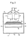
- Fig. 2 einen schematischen Querschnitt nach Linie II-II der Fig. 1,
- Fig. 3 eine Variante der Anlagen von Fig. 1.
- 1 is a schematic side view of a part of a plant which processes cotton flakes,
- 2 shows a schematic cross section along line II-II of FIG. 1,
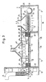
- 3 shows a variant of the systems from FIG. 1.
In Fig. 1 bedeutet das Bezugszeichen 13 den Ausgangsschacht einer kombinierten Misch- und Reinigungsmaschine 10, z.B. Rieter Unimix B 7/3 oder Mischöffner B 3/3, welche vor dem erfindungsgemässen Mikrowellenofen 11 angeordnet ist, dem eine Auflöseeinheit 12 nachgeschaltet ist. Bei dieser Auflöseeinheit kann es sich um die Auflöseeinheit einer Feinreinigungsmaschine, z.B. des Rieter ERM-Reinigers handeln.In Fig. 1, reference numeral 13 denotes the outlet shaft of a combined mixing and
Die im Ausgangsschacht 13 des kombinierten Reinigers 10 vorhandenen Faserflocken, welche eine Mischung aus Baumwollflocken verschiedener Provinenzen darstellen können, werden durch eine Führungswalze 14 und zwei Abzugswalzen 15 und 16 zu einem leicht komprimierten Flockenvlies 17 gebildet, welches kontinuierlich auf einem umlaufenden Förderband 18 abgelegt wird. Das Förderband 18, das aus einem Mikrowellen kaum oder gar nicht absorbierenden Stoff besteht, z.B. aus Polypropylen, ist um zwei Umlenkrollen 19 und 21 geführt, wovon die Umlenkrolle 21 durch einen Motor (nicht gezeigt) angetrieben wird. Auch können weitere Umlenk- und Spannrollen vorgesehen werden; diese sind jedoch ebenfalls nicht gezeigt. Wie ersichtlich, ist die erste Umlenkrolle 19 bereits kurz nach dem Abzugswalzenpaar 15, 16 der kombinierten Reinigers 10 angeordnet und von diesem mittels eines Führungsbleches 22 für das Vlies 17 getrennt. Die angetriebene Umlenkrolle 21 befindet sich unmittelbar nach dem Ausgang des Mikrowellenofens 11 vor den Einzugswalzen 23, 24 der Auflöseeinheit 12, welche im weiteren Verlauf des Faservlieses 17 aus Speisewalzen 25, 26, einer Reinigungswalze 27 und einem Rost 28 besteht. Das vom Förderband erhaltene Vlies 17 wird durch die Reinigungswalze 27 aufgelöst und gereinigt und die aufgelösten Flocken werden anschliessend in einen senkrecht nach oben steigenden Schacht 29 gespeist, welcher zu einem Flockenspeiser (nicht dargestellt) führt.The fiber flakes present in the outlet shaft 13 of the combined
Der Mikrowellenofen 11 besteht, wie auch in Fig. 2 ersichtlich, aus zwei Reihen 30.1, 30.2 von je sechs Mikrowellenerzeugern 31. Das auf dem Förderband abgelegte Vlies 17, das eine Breite von 1 m und eine Dicke von etwa 10 cm hat, liegt etwa 15 cm unterhalb der unteren Enden der Mikrowellenerzeuger 31, so dass die von diesen Mikrowellenerzeugern ausgestrahlten Mikrowellen die Möglichkeit haben, sich gleichmässig über die Breite des Vlieses zu verteilen. Diese Verteilung wird durch Mehrfachreflexionen an den metallischen Wänden 32 des Mikrowellengehäuses 33 bzw. an einer unterhalb des oberen Trums 34 des Förderbandes 18 vorgesehenen metallischen Stützplatte 35 begün stigt.The
Um zu verhindern, dass die durch Mehrfachreflexionen abgelenkten Strahlungen durch den Eingang oder Ausgang des Mikrowellenofens austreten, sind Abschirmbleche 36 vorgesehen, welche eingangs- und ausgangsseitig angebracht sind und sich von der Unterseite der Mikrowellenerzeuger bis kurz oberhalb der Oberfläche des Vlieses 17 hinuntererstrecken. Weiter sind um den rechteckigen Einlass 37 und um den rechteckigen Auslass 38 des Mikrowellenofens herum jeweilige parallele Anordnungen von Ferritstäben 39, 41 angeordnet, welche etwaige noch vorhandene Mikrowellen absorbieren und somit verhindern, das diese Mikrowellen in das Gehäuse der kombinierten Reinigungsmaschine 10 oder auf diese Weise zu der Auflöseeinheit 12 gelangen. Somit werden diese Bestrahlungen vom Betriebspersonal ferngehalten.In order to prevent the radiation deflected by multiple reflections from escaping through the entrance or exit of the microwave oven,
Oberhalb der Mikrowellenerzeuger 31 ist die Oberseite des Mikrowellenofengehäuses 33 als Abzugshaube 42 ausgebildet, wobei ein Gebläse (nicht gezeigt) die durch die Mikrowellenaufwärmung erzeugten Dämpfe über einen am oberen Ende der Haube 42 vorgesehen Stutzen 43 absaugt.Above the
Innerhalb des Gehäuses 33 sind verschiedene IR-Meldesensoren 44 vorgesehen, welche an ein Steuersystem angeschlossen sind. Sollte im Betrieb eine lokale Überhitzung erfolgen, so wird über das Steuersystem die Anlage, vor allem die Mikrowellenerzeuger 31 abgeschaltet und es wird über die Düsen 45 ein Halon-Löschgas in das Gehäuse eingebracht, wodurch Sauerstoff verdrängt und ein Feuerausbruch verhindert bzw. ein entstehender Brand sofort gelöscht wird.Various
Eine Leistungssteuerung der einzelnen Mikrowellenerzeuger ist innerhalb von gewissen Grenzen möglich, die Gesamtleistung der Anlage kann jedoch innerhalb von breiten Grenzen durch Ein- oder Ausschalten einzelner Mikrowellenerzeuger erreicht werden.Power control of the individual microwave generators is possible within certain limits, but the overall performance of the system can be achieved within wide limits by switching individual microwave generators on or off.
Auf diese Weise lässt sich die Wärmezufuhr leicht am Feuchtigkeitsgehalt der Baumwolle und der Honigtauverunreinigung anpassen.In this way, the heat supply can be easily adjusted to the moisture content of the cotton and the honeydew contamination.
Die Mikrowellengeräte selbst arbeiten mit 12 cm Wellenlänge bei einer Frequenz von 2,45 Gigahertz.The microwave devices themselves work with a 12 cm wavelength at a frequency of 2.45 gigahertz.
Die Energiezufuhr zu dem Vlies soll so bemessen werden, dass unter Berücksichtigung der Durchlaufgeschwindigkeit des Förderbandes die Honigtauablagerungen auf etwa 140° C aufgewärmt werden, was ausreicht, um etwa 80 % des darin enthaltenen Wassers zu entziehen und die Ablagerungen in einen gut verarbeitbaren, nichtklebrigen Zustand zu überführen.The energy supply to the fleece should be dimensioned such that, taking into account the throughput speed of the conveyor belt, the honeydew deposits are warmed up to approximately 140 ° C., which is sufficient to extract approximately 80% of the water contained therein and the deposits in a readily processable, non-sticky state to convict.
Schliesslich muss erwähnt werden, dass es möglich ist, innerhalb des Mikrowellenofengehäuses steuerbare Abweiser 46 zur Steuerung der Mikrowellen vorzusehen, wobei solche Abweiser 46 in der Fig. 2 zwischen den benachbarten Reihen 30.1, 30.2, von Mikrowellenerzeugern zu ersehen sind. Diese Abweiser können so angesteuert werden, dass eine gleichmässige Energieverteilung über die gesamte Breite des Vlieses erhalten wird, ohne dass die in der Mitte des Vlieses erhaltene Strahlung von beiden benachbarten Mikrowellenerzeugern dort zu einer lokalen Ueberhitzung des Vlieses bzw. der Honigtauablagerungen führt. Diese Ab weiser werden normalerweise bei der Herstellung des Mikrowellenofens ein für allemal eingestellt unter Berücksichtigung der Eigenschaften der dort eingebauten Mikrowellenerzeuger.Finally, it must be mentioned that it is possible to provide
Die Fig. 3 zeigt insofern eine Variante der Vorrichtung von Fig. 1, indem zwischen der Umlenkrolle 21 des Förderbandes 18 und den Einzugswalzen 23 und 24 eine Kühlzone 70 vorgesehen ist, um die erwärmte Faserwatte zwischen zwei Kühl-Förderbändern 71 und 72 zu kühlen. Die Kühlzone 70 wird durch eine Absaughaube 73 überdeckt, an welcher ein Anschlussstutzen 74 vorgesehen ist. Dieser Anschlussstutzen 74 ist mit einem Saugventilator (nicht gezeigt) verbunden, um die Luftströmung L durch die Kühl-Förderbänder 71 und 72 zu erzeugen.3 shows a variant of the device of FIG. 1 in that a
In den Wänden welche, die Kühlzone und die Auflöseeinheit 12, zu welcher die Einzugswalzen 23 und 24 gehören, umschliessen, sind Lufteintrittsöffnungen (nicht gezeigt) vorgesehen, um das Einströmen der vorgenannten Luftströmung L und der Luft für den Schacht 29 zu ermöglichen.Air inlet openings (not shown) are provided in the walls which surround the cooling zone and the dissolving
Je nach gewünschtem Luftfeuchtigkeitsgehalt und je nach gewünschter Lufttemperatur der Luftströmung L kann den vorgenannten Lufteintrittsöffnungen noch eine Luftklimatisierungseinrichtung (nicht gezeigt) vorgeschaltet werden.Depending on the desired air moisture content and the desired air temperature of the air flow L, an air conditioning device (not shown) can be connected upstream of the aforementioned air inlet openings.
Die Förderbänder 71 und 72 sind synchron durch einen einzigen Antrieb (nicht gezeigt) angetrieben und fördern die Faserwatte mit der Ausgangsgeschwindigkeit der Faserwatte auf dem Förderband 18.The
Als weitere Variante (nicht gezeigt) besteht auch die Möglichkeit, die Faserwatte nach der Auflöseeinheit 12 zu kühlen, indem der Schacht 29 einen Querschnitt und eine Länge aufweist, welche die Kühlung während der Förderung ermöglicht. In einem solchen Falle wird die Luftgeschwindigkeit im Schacht 29 wenig über der Schwebegeschwindigkeit der Faserflocken sein, um eine genügende Verweildauer ohne allzu grosse Höhe des Schachtes zu ermöglichen. Ebenso besteht die Möglichkeit, die in den Schacht 29 eingesaugte Luft vorher zu klimatisieren.As a further variant (not shown), there is also the possibility of cooling the fiber wadding after the dissolving
Claims (18)
Applications Claiming Priority (2)
| Application Number | Priority Date | Filing Date | Title |
|---|---|---|---|
| CH2121/88 | 1988-06-03 | ||
| CH212188 | 1988-06-03 |
Publications (2)
| Publication Number | Publication Date |
|---|---|
| EP0344729A1 true EP0344729A1 (en) | 1989-12-06 |
| EP0344729B1 EP0344729B1 (en) | 1995-06-21 |
Family
ID=4226369
Family Applications (1)
| Application Number | Title | Priority Date | Filing Date |
|---|---|---|---|
| EP89109777A Expired - Lifetime EP0344729B1 (en) | 1988-06-03 | 1989-05-30 | Method and apparatus for treating cotton fibres contaminated by honey dew |
Country Status (9)
| Country | Link |
|---|---|
| US (2) | US5048156A (en) |
| EP (1) | EP0344729B1 (en) |
| JP (1) | JPH0226910A (en) |
| KR (1) | KR920005792B1 (en) |
| CN (1) | CN1019210B (en) |
| AT (1) | ATE124097T1 (en) |
| DE (2) | DE3819883A1 (en) |
| IL (1) | IL90240A (en) |
| RU (1) | RU1836505C (en) |
Cited By (6)
| Publication number | Priority date | Publication date | Assignee | Title |
|---|---|---|---|---|
| EP0375629A1 (en) * | 1988-12-21 | 1990-06-27 | Edoardo Polli | Method and apparatus for processing cotton bales for removing fungi and micro-organisms therefrom |
| US4989297A (en) * | 1985-02-28 | 1991-02-05 | Shenkar College Of Textile Technology And Fashion | Treatment of cotton |
| FR2664796A1 (en) * | 1990-07-18 | 1992-01-24 | Moreau Sa | Method for cleaning roots and tubers, especially beet, after they have been pulled out (lifted) |
| EP0542166A1 (en) * | 1991-11-15 | 1993-05-19 | CASCAMI SETA - FILATURE SERICHE RIUNITE SpA | Method to separate polypropylene in the processing of silk and device to separate polypropylene which employs such method |
| FR2685709A1 (en) * | 1991-12-30 | 1993-07-02 | Cirad | COTTON TREATMENT PROCESS AND PLANT FOR APPLYING THE PROCESS. |
| WO2005066404A1 (en) * | 2003-12-19 | 2005-07-21 | Spinner, Hermann | Method for removing honeydew and synthetic fibres of fibrous materials and device for carrying out said method |
Families Citing this family (15)
| Publication number | Priority date | Publication date | Assignee | Title |
|---|---|---|---|---|
| IL92299A0 (en) * | 1989-11-14 | 1990-07-26 | Israel Fiber Inst State Of Isr | Process and device for the treatment of cotton |
| FR2691545B1 (en) * | 1992-05-20 | 1994-07-13 | Cirad | METHOD AND INSTALLATION FOR EVALUATING THE STICKY CHARACTER OF VEGETABLE FIBROUS MATERIALS SUCH AS COTTONS AND USE OF THIS PROCESS AND THE SAME. |
| AU2001248711A1 (en) * | 2000-05-01 | 2001-11-12 | Xorella Ag | Method for the heat treatment of bales |
| DE10104320A1 (en) * | 2001-01-25 | 2002-08-01 | Univ Schiller Jena | Device for performing safety functions in rooms with high-frequency radiation |
| WO2003062970A1 (en) * | 2001-12-24 | 2003-07-31 | Lg Electronics Inc. | Hinge assembly for flat panel display appliance |
| WO2003056415A1 (en) * | 2001-12-24 | 2003-07-10 | Lg Electronics Inc. | Hinge assembly for flat panel display appliance |
| WO2003056414A1 (en) * | 2001-12-24 | 2003-07-10 | Lg Electronics Inc. | Hinge assembly for flat panel display appliance |
| US20040188430A1 (en) * | 2003-03-31 | 2004-09-30 | Qazi Ghulam Nabi | Microbial decontaminator |
| CN100439840C (en) * | 2006-01-05 | 2008-12-03 | 卓卫民 | A microwave heating equipment with metal chain transmission |
| DE102007063374A1 (en) * | 2007-12-30 | 2009-07-02 | Dieffenbacher Gmbh + Co. Kg | Method and device for preheating a pressed material mat in the course of the production of wood-based panels |
| US8046877B2 (en) * | 2008-08-26 | 2011-11-01 | Jimmy R. Stover | Drying of seed cotton and other crops |
| US20100307120A1 (en) * | 2009-06-05 | 2010-12-09 | Stover Jimmy R | Harvester with heated duct |
| CN103103704A (en) * | 2012-12-11 | 2013-05-15 | 吴江兰瑞特纺织品有限公司 | Fluffy device of microwave batts |
| US9739530B2 (en) | 2014-02-28 | 2017-08-22 | Jimmy Ray Stover | Microwave drying of seed cotton and other crops |
| DE102017104061A1 (en) * | 2017-02-27 | 2018-08-30 | Dieffenbacher GmbH Maschinen- und Anlagenbau | Continuous furnace for heating material by means of microwaves |
Citations (5)
| Publication number | Priority date | Publication date | Assignee | Title |
|---|---|---|---|---|
| CH557435A (en) * | 1970-11-12 | 1974-12-31 | Oreal | METHOD FOR RAISING THE TEMPERATURE OF TEXTILE FIBERS. |
| GB2030440A (en) * | 1978-09-11 | 1980-04-10 | Philip Morris Inc | Method for the manufacture of fibrous articles |
| DE3430673A1 (en) * | 1984-08-21 | 1986-02-27 | Hermann Berstorff Maschinenbau Gmbh, 3000 Hannover | Device for the pasteurisation and sterilisation of free-flowing materials |
| EP0196449A1 (en) * | 1985-02-28 | 1986-10-08 | THE SHENKAR COLLEGE OF TEXTILE TECHNOLOGY & FASHION | Process and device for rendering harmless sticky material adhering to cotton fibers |
| DE3538899A1 (en) * | 1985-11-02 | 1987-05-07 | Hauni Werke Koerber & Co Kg | Installation for microwave treatment of an article |
Family Cites Families (10)
| Publication number | Priority date | Publication date | Assignee | Title |
|---|---|---|---|---|
| DE175338C (en) * | ||||
| GB433091A (en) * | 1934-07-25 | 1935-08-08 | Preston Street Combing Co Ltd | Improvements in combing machines |
| DE1133286B (en) * | 1959-10-06 | 1962-07-12 | Fritz Hadwich Dipl Ing | Method and device for separating solid and heat-softenable foreign bodies from a fiber pile |
| GB1294648A (en) * | 1969-06-25 | 1972-11-01 | Unisearch Ltd | Apparatus for drying textile materials |
| NL189363C (en) * | 1977-03-17 | 1993-03-16 | Truetzschler Gmbh & Co Kg | Apparatus for collecting and summarizing fibrous membranes. |
| SU771425A1 (en) * | 1978-11-02 | 1980-10-15 | За витель | Apparatus for drying fibrous material |
| US4631380A (en) * | 1983-08-23 | 1986-12-23 | Durac Limited | System for the microwave treatment of materials |
| NL8402999A (en) * | 1984-10-02 | 1986-05-01 | Philips Nv | MICROWAVE DEVICE FOR HEATING MATERIAL. |
| GB2182149B (en) * | 1985-10-25 | 1989-12-20 | Coal Ind | Improved moisture meter |
| IT8721377A0 (en) * | 1987-07-21 | 1987-07-21 | Edoardo Polli | PROCEDURE AND EQUIPMENT FOR THE TREATMENT OF TEXTILE FIBERS, IN PARTICULAR COTTON IN PRESSED BALES, FOR THE REMOVAL OR REDUCTION FROM SUCH FIBERS OF ANY ORGANIC RESIDUE OF INSECTS ADHERING TO THEM. |
-
1988
- 1988-06-10 DE DE3819883A patent/DE3819883A1/en not_active Withdrawn
-
1989
- 1989-05-09 IL IL90240A patent/IL90240A/en unknown
- 1989-05-30 EP EP89109777A patent/EP0344729B1/en not_active Expired - Lifetime
- 1989-05-30 AT AT89109777T patent/ATE124097T1/en not_active IP Right Cessation
- 1989-05-30 RU SU894614194A patent/RU1836505C/en active
- 1989-05-30 DE DE58909304T patent/DE58909304D1/en not_active Expired - Fee Related
- 1989-05-31 US US07/359,495 patent/US5048156A/en not_active Expired - Lifetime
- 1989-06-02 JP JP1139391A patent/JPH0226910A/en active Pending
- 1989-06-03 CN CN89103702A patent/CN1019210B/en not_active Expired
- 1989-06-03 KR KR1019890007651A patent/KR920005792B1/en not_active Expired
-
1990
- 1990-04-02 US US07/503,524 patent/US5008978A/en not_active Expired - Fee Related
Patent Citations (5)
| Publication number | Priority date | Publication date | Assignee | Title |
|---|---|---|---|---|
| CH557435A (en) * | 1970-11-12 | 1974-12-31 | Oreal | METHOD FOR RAISING THE TEMPERATURE OF TEXTILE FIBERS. |
| GB2030440A (en) * | 1978-09-11 | 1980-04-10 | Philip Morris Inc | Method for the manufacture of fibrous articles |
| DE3430673A1 (en) * | 1984-08-21 | 1986-02-27 | Hermann Berstorff Maschinenbau Gmbh, 3000 Hannover | Device for the pasteurisation and sterilisation of free-flowing materials |
| EP0196449A1 (en) * | 1985-02-28 | 1986-10-08 | THE SHENKAR COLLEGE OF TEXTILE TECHNOLOGY & FASHION | Process and device for rendering harmless sticky material adhering to cotton fibers |
| DE3538899A1 (en) * | 1985-11-02 | 1987-05-07 | Hauni Werke Koerber & Co Kg | Installation for microwave treatment of an article |
Cited By (8)
| Publication number | Priority date | Publication date | Assignee | Title |
|---|---|---|---|---|
| US4989297A (en) * | 1985-02-28 | 1991-02-05 | Shenkar College Of Textile Technology And Fashion | Treatment of cotton |
| EP0375629A1 (en) * | 1988-12-21 | 1990-06-27 | Edoardo Polli | Method and apparatus for processing cotton bales for removing fungi and micro-organisms therefrom |
| FR2664796A1 (en) * | 1990-07-18 | 1992-01-24 | Moreau Sa | Method for cleaning roots and tubers, especially beet, after they have been pulled out (lifted) |
| EP0542166A1 (en) * | 1991-11-15 | 1993-05-19 | CASCAMI SETA - FILATURE SERICHE RIUNITE SpA | Method to separate polypropylene in the processing of silk and device to separate polypropylene which employs such method |
| US5305497A (en) * | 1991-11-15 | 1994-04-26 | Cascami Seta-Filature Seriche Riunite Spa | Method to separate polypropylene in the processing of silk and device to separate polypropylene which employs such method |
| FR2685709A1 (en) * | 1991-12-30 | 1993-07-02 | Cirad | COTTON TREATMENT PROCESS AND PLANT FOR APPLYING THE PROCESS. |
| WO1993013253A1 (en) * | 1991-12-30 | 1993-07-08 | Centre International En Recherche Agronomique Pour Le Developpement (Cirad) | Process for cotton treatment by hot steam injection and plant for carrying out said process |
| WO2005066404A1 (en) * | 2003-12-19 | 2005-07-21 | Spinner, Hermann | Method for removing honeydew and synthetic fibres of fibrous materials and device for carrying out said method |
Also Published As
| Publication number | Publication date |
|---|---|
| DE58909304D1 (en) | 1995-07-27 |
| IL90240A0 (en) | 1989-12-15 |
| CN1019210B (en) | 1992-11-25 |
| DE3819883A1 (en) | 1989-12-07 |
| US5008978A (en) | 1991-04-23 |
| IL90240A (en) | 1993-02-21 |
| JPH0226910A (en) | 1990-01-29 |
| RU1836505C (en) | 1993-08-23 |
| KR920005792B1 (en) | 1992-07-18 |
| CN1040231A (en) | 1990-03-07 |
| ATE124097T1 (en) | 1995-07-15 |
| KR900000539A (en) | 1990-01-30 |
| EP0344729B1 (en) | 1995-06-21 |
| US5048156A (en) | 1991-09-17 |
Similar Documents
| Publication | Publication Date | Title |
|---|---|---|
| EP0344729B1 (en) | Method and apparatus for treating cotton fibres contaminated by honey dew | |
| DE3003814C2 (en) | Method and apparatus for removing linters from cottonseed | |
| DE3135247A1 (en) | AIR CONDITIONING IN THE MANUFACTURE OF NEEDLE DRUM MATS | |
| DE60222150T2 (en) | Machine and method for the continuous treatment of a fabric | |
| DE10349374B4 (en) | Wet treatment machine for rope-shaped textile goods | |
| DE2755380A1 (en) | DEVICE FOR OPENING AND CLEANING COTTON WASTE | |
| DE102019114016B4 (en) | Method and device for heating a pressed material mat | |
| DE1510395B1 (en) | Method and device for opening fiber flocks, in particular for producing fiber fleece | |
| EP0352591B1 (en) | Apparatus and method for treating textiles | |
| EP0344631B1 (en) | Method and apparatus for lowering the stickyness of cotton | |
| EP0350669B1 (en) | Method for reducing the stickyness of cotton flock fibres contaminated with honey dew | |
| DE3605100C2 (en) | ||
| DE941384C (en) | Method and device for the production of fibers from fiber-forming materials | |
| DE2950367C2 (en) | Card or card with a casing | |
| DE4320638A1 (en) | Rapid cooling of hot rolled material, esp. wire - uses air stream containing a water mist | |
| DE10041838A1 (en) | Structuring fibers in fleece formed aerodynamically, is achieved by passing between endless belts which compress it to desired final dimension | |
| DE1635123A1 (en) | Device for treating, preferably steaming and fixing dye, in particular textile goods | |
| WO1994003406A1 (en) | Thermal treatment process and device for waste and/or residual materials | |
| DE2605003C3 (en) | Process for the production of nonwovens and apparatus for carrying out the process | |
| DE4124702A1 (en) | Transfer appts. to carry web to condenser - has row of jets below gap between roller and guide plate with jet to roll web into silver | |
| DE3501684C2 (en) | ||
| AT244011B (en) | Process for producing fibers from viscous masses and apparatus for carrying out the process | |
| DE2122039A1 (en) | Process for the production of a fiber carpet or fiber fleece and device for carrying out this process | |
| DE2628676B1 (en) | METHOD AND DEVICE FOR CONTINUOUS PRINTING OF TEXTILE WEBS | |
| DE2806746A1 (en) | HEAT TREATMENT DEVICE |
Legal Events
| Date | Code | Title | Description |
|---|---|---|---|
| PUAI | Public reference made under article 153(3) epc to a published international application that has entered the european phase |
Free format text: ORIGINAL CODE: 0009012 |
|
| AK | Designated contracting states |
Kind code of ref document: A1 Designated state(s): AT CH DE FR GB IT LI |
|
| 17P | Request for examination filed |
Effective date: 19900112 |
|
| 17Q | First examination report despatched |
Effective date: 19910709 |
|
| GRAA | (expected) grant |
Free format text: ORIGINAL CODE: 0009210 |
|
| AK | Designated contracting states |
Kind code of ref document: B1 Designated state(s): AT CH DE FR GB IT LI |
|
| PG25 | Lapsed in a contracting state [announced via postgrant information from national office to epo] |
Ref country code: FR Effective date: 19950621 |
|
| REF | Corresponds to: |
Ref document number: 124097 Country of ref document: AT Date of ref document: 19950715 Kind code of ref document: T |
|
| REF | Corresponds to: |
Ref document number: 58909304 Country of ref document: DE Date of ref document: 19950727 |
|
| ITF | It: translation for a ep patent filed | ||
| GBT | Gb: translation of ep patent filed (gb section 77(6)(a)/1977) |
Effective date: 19950829 |
|
| EN | Fr: translation not filed | ||
| PLBE | No opposition filed within time limit |
Free format text: ORIGINAL CODE: 0009261 |
|
| STAA | Information on the status of an ep patent application or granted ep patent |
Free format text: STATUS: NO OPPOSITION FILED WITHIN TIME LIMIT |
|
| PGFP | Annual fee paid to national office [announced via postgrant information from national office to epo] |
Ref country code: CH Payment date: 19960502 Year of fee payment: 8 |
|
| PG25 | Lapsed in a contracting state [announced via postgrant information from national office to epo] |
Ref country code: AT Effective date: 19960530 |
|
| 26N | No opposition filed | ||
| PG25 | Lapsed in a contracting state [announced via postgrant information from national office to epo] |
Ref country code: LI Free format text: LAPSE BECAUSE OF NON-PAYMENT OF DUE FEES Effective date: 19970531 Ref country code: CH Free format text: LAPSE BECAUSE OF NON-PAYMENT OF DUE FEES Effective date: 19970531 |
|
| REG | Reference to a national code |
Ref country code: CH Ref legal event code: PL |
|
| PGFP | Annual fee paid to national office [announced via postgrant information from national office to epo] |
Ref country code: GB Payment date: 20010423 Year of fee payment: 13 |
|
| REG | Reference to a national code |
Ref country code: GB Ref legal event code: IF02 |
|
| PGFP | Annual fee paid to national office [announced via postgrant information from national office to epo] |
Ref country code: DE Payment date: 20020502 Year of fee payment: 14 |
|
| PG25 | Lapsed in a contracting state [announced via postgrant information from national office to epo] |
Ref country code: GB Free format text: LAPSE BECAUSE OF NON-PAYMENT OF DUE FEES Effective date: 20020530 |
|
| GBPC | Gb: european patent ceased through non-payment of renewal fee |
Effective date: 20020530 |
|
| PG25 | Lapsed in a contracting state [announced via postgrant information from national office to epo] |
Ref country code: DE Free format text: LAPSE BECAUSE OF NON-PAYMENT OF DUE FEES Effective date: 20031202 |
|
| PG25 | Lapsed in a contracting state [announced via postgrant information from national office to epo] |
Ref country code: IT Free format text: LAPSE BECAUSE OF NON-PAYMENT OF DUE FEES Effective date: 20050530 |