EP0344582A1 - Hose or tube coupling for aggressive fluids - Google Patents
Hose or tube coupling for aggressive fluids Download PDFInfo
- Publication number
- EP0344582A1 EP0344582A1 EP89109300A EP89109300A EP0344582A1 EP 0344582 A1 EP0344582 A1 EP 0344582A1 EP 89109300 A EP89109300 A EP 89109300A EP 89109300 A EP89109300 A EP 89109300A EP 0344582 A1 EP0344582 A1 EP 0344582A1
- Authority
- EP
- European Patent Office
- Prior art keywords
- bellows
- plate
- spring
- coupling
- valve
- Prior art date
- Legal status (The legal status is an assumption and is not a legal conclusion. Google has not performed a legal analysis and makes no representation as to the accuracy of the status listed.)
- Granted
Links
Images


Classifications
-
- F—MECHANICAL ENGINEERING; LIGHTING; HEATING; WEAPONS; BLASTING
- F16—ENGINEERING ELEMENTS AND UNITS; GENERAL MEASURES FOR PRODUCING AND MAINTAINING EFFECTIVE FUNCTIONING OF MACHINES OR INSTALLATIONS; THERMAL INSULATION IN GENERAL
- F16K—VALVES; TAPS; COCKS; ACTUATING-FLOATS; DEVICES FOR VENTING OR AERATING
- F16K41/00—Spindle sealings
- F16K41/10—Spindle sealings with diaphragm, e.g. shaped as bellows or tube
-
- F—MECHANICAL ENGINEERING; LIGHTING; HEATING; WEAPONS; BLASTING
- F16—ENGINEERING ELEMENTS AND UNITS; GENERAL MEASURES FOR PRODUCING AND MAINTAINING EFFECTIVE FUNCTIONING OF MACHINES OR INSTALLATIONS; THERMAL INSULATION IN GENERAL
- F16L—PIPES; JOINTS OR FITTINGS FOR PIPES; SUPPORTS FOR PIPES, CABLES OR PROTECTIVE TUBING; MEANS FOR THERMAL INSULATION IN GENERAL
- F16L29/00—Joints with fluid cut-off means
- F16L29/04—Joints with fluid cut-off means with a cut-off device in each of the two pipe ends, the cut-off devices being automatically opened when the coupling is applied
Definitions
- the bellows completely encloses the spring together with the plate, so that contact with the aggressive liquid of the piping system is excluded.
- the construction of the bellows is inexpensive, the sealing on the bottom is done by clamping the collar between two plastic parts of the sleeve and the plate, which are preferably screwed into an internally molded piece of the coupling body or fastened here, the latter leaving peripheral coaxial channels to the inside wall of the coupling body .
- the bellows can be formed separately from the valve cone. Since the valve cone rests under spring pressure on a corresponding counter cone of the coupling mouth and when opening, i.e. Pushing back this compression spring is reinforced, the parts do not have to be attached to each other. However, an embodiment is particularly preferred in which the valve cone and bellows are made in one piece from plastic (polytetrafluoroethylene), i.e. in particular (from the solid) are turned. Since the opening and closing paths can be relatively short, there is no increased requirement for the elasticity of the bellows.
- the bellows can have a cylindrical area between the molded collar and the actual accordion-like part, which abuts the inner wall of the sleeve and which on the other hand is pressed against the sleeve by the internal spring, so that a gap-free transition from the upper sleeve edge into the liquid leading area of the valve is guaranteed.
- the cylindrical region can in particular be reinforced here.
- the sleeve with an annular abutment on the sleeve, which on the one hand fixes the sleeve via the surface pressure and, on the other hand, can be rounded in order to avoid edges lying in the flow.
- the valve cone In the closed state, however, the valve cone is not in full contact with a corresponding counter cone, so that an annular gap is free when pushed back about the closing path.
- the cones preferably have cylindrical extensions, the length of which corresponds to the closing path and which are surrounded by a corresponding constriction of the closing part of the coupling body at a radial distance in order to limit the dead volume that occurs here.
- the cones In order to specify the mutual opening of the valve cones when the coupling parts are closed, the cones have mutually engaging guide parts.
- the plate In order to facilitate the assembly of the bellows and to increase the tightness of the bellows enclosing the spring by a positive guide, the plate has an annular groove into which the lower, i.e. the edge of the bellows opposite the valve cone engages. In this way, the bellows is forced into a fixed position and cannot slip when clamping its collar between the sleeve and the plate.
- a coupling part I according to the invention is shown on the right, as it is basically usable for everyone. It consists of a cylindrical coupling body 8, on the inner wall of which an inner threaded piece 7 is fastened, which has openings as channels 9 to the inner wall. A connection 21 for a hose line is shown at the end.
- a sleeve 6 is screwed in from the opposite side and is provided with an annular stop 23 which rests on the edge of the sleeve 6.
- the cylindrical region 10 of a bellows 2 lies against the inner wall of the sleeve 6 and is held from the inside against the inner wall of the sleeve by a metallic spring 1.
- the spring 1 is supported against the plate 3 and presses a valve cone 4 against a counter cone 25 of the valve body 8.
- valve cone 4, bellows 2 and cylindrical extension 24 are made in one piece from PTFE (turned), with the end facing the plate 3 the area 10 a collar 5 is formed, the spring 1 is held sealingly between the sleeve 23 and the plate 3 by screwing the two parts against each other.
- a sealing ring can be inserted into the annular groove 22.
- a coupling part can be used on its own, with a counterpart only having to have a central mandrel or the like in order to open the valve cone against the spring tension when coupling.
- the solution shown here is preferred, in which a part II with the same effect is combined with part I.
- the coupling part I has a union nut 26 which connects the two to one another via the thread 27 of the part II.
- Parts I and II have projections 17 projecting beyond the cone 4, which rest in the coupling openings 24.
- the coupling openings 24 or the extensions 17 and the screw connection 26, 27 are dimensioned such that the cones 4 lift off from the counter cones 25 and open the flow path for the liquid.
- a safe, uniform opening of both cones 4 is ensured by a stop 12, which is assigned a weaker spring 1 'in the coupling part II, which is first pressed back by the spring 1 against it.
- the stop 12 can be adjustably mounted in the plate 3 'in a thread.
- the stop 12 can leak directly against the cone 4 ', in the illustration the cone 4' has a plunger 14, against which the stop 12 is in the open position of the coupling parts I and II.
- All liquid-carrying parts (not springs 1 and 1 ') are made of plastic (PTFE), so that a high tightness is guaranteed.
- O-rings 27 also made of PTFE can be used.
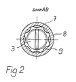
- FIG. 2 shows the section according to FIG. 1.
- the plate 3 is screwed into the internal threaded piece 7.
- the assemblability of the parts can be ensured, for example, by either detachably connecting the internal threaded piece to the coupling body 8 or by making it divisible between the internal threaded piece 7 and the counter cone 25 (FIG. 1).
- Fig. 3 shows the two coupling parts I and II in the closed state to form an annular constricted gap around the valve cone 4, 4 'and the extensions 17, 17'.
- the plunger 14 bears against the stop 12, the union nut 26 is screwed to the thread 27.
- the coupling bodies 8 When the clutch is opened, the coupling bodies 8 first move away from one another as a result of the necessary closing travel until the cones 4, 4 'rest on their counter cones 25. This creates a gap between the coupling bodies, which is undesirably filled with liquid, increasing the dead volume.
- the coupling part II has a spring-loaded sealing ring 19 which lies in an annular space 27 and is prestressed by a spring 28.
- a flange 28 of the coupling part I bears against the sealing ring 19 of the coupling part II. If you now open the screw connection 26, 27, where the sealing ring 19 is pushed out by the spring 28 and lies against the end face of the flange 28 until it is completely open, so that a radially outward reach of the dead volume cannot be filled with liquid.
Abstract
Description
In der Halbleiterindustrie werden mittlerweile für Rohre und Schläuche Kupplungen benötigt, die sich von allen herkömmlichen Kupplungen dadurch unterscheiden müssen, daß sie völlig stahl- (also auch edelstahl-) und metallfrei sein müssen, da bereits geringste Metallspuren als Verunreinigung der transportierten Flüssigkeit ausgeschlossen werden müssen. (Unter Flüssigkeit wird dabei ggf. auch ein Gas verstanden).
Sie müssen daher aus resistenten Kuntstoffen hergestellt werden, nur O-Ringe - falls überhaupt - aus PTFE besitzen und so konstruiert sein, daß die Fließfähigkeit möglichst nicht durch Ecken, Kanten und Absätze gestört wird. Beim Koppeln soll möglichst keine Leckage entstehen.In the semiconductor industry, couplings are now required for pipes and hoses, which must differ from all conventional couplings in that they must be completely free of steel (including stainless steel) and metal, since even the slightest traces of metal must be excluded as contamination of the transported liquid . (Liquid may also be understood as a gas).
They must therefore be made of resistant plastic, only have O-rings - if at all - made of PTFE and constructed so that the flowability is not disturbed by corners, edges and shoulders. There should be no leakage when coupling.
Die Lösung dieser Aufgabe gelingt mit Hilfe einer Kupplung für Rohre oder Schläuche bestehend aus zwei Elementen, welche mit einer Schraub-, Steck- oder Klemmverbindung flüssigkeitsdicht aneinander befestigt werden können, die Ventilvorrichtungen enthalten, welche im gekuppelten Zustand die Rohre abdichten und aus einem Ventilkegel bestehen, der ungekuppelt durch eine Feder gegen den Innenkegel des Ventilsitzes gerückt und durch ein Gegenstück des anderen Elements gegen die Feder geöffnet wird, die sich gegen eine Platte im Kupplungskörper abstützt, wobei erfindungsgemäß die Feder gegen die Flüssigkeit abgedichtet in einem Faltenbalg untergebracht ist, der sich von der Platte bis zum Ventilkegel erstreckt. Der Faltenbalg weist einen unteren Kragen auf und ist mit Hilfe einer Hülse gegen die Platte im Preßsitz gehalten, Faltenbalg und Kragen sind einstückig und ebenso wie alle mit Flüssigkeit in Berührung kommende Teile aus Kunststoff ausgebildet.This problem is solved with the aid of a coupling for pipes or hoses consisting of two elements which can be fastened to one another in a liquid-tight manner by means of a screw, plug or clamp connection, which contain valve devices which, when coupled, seal the pipes and consist of a valve cone , which is uncoupled by a spring against the inner cone of the valve seat and opened by a counterpart of the other element against the spring, which is supported against a plate in the coupling body, the spring being sealed against the liquid being accommodated in a bellows which is sealed against the liquid extends from the plate to the valve cone. The bellows has a lower collar and is held in a press fit against the plate by means of a sleeve, the bellows and collar are in one piece and, like all parts coming into contact with liquid, are made of plastic.
Der Faltenbalg umschließt hierbei die Feder zusammen mit der Platte vollständig, so daß eine Berührung mit der aggressiven Flüssigkeit des Rohrleitungssystems ausgeschlossen ist. Die Konstruktion des Faltenbalges ist unaufwendig, die bodenseitige Abdichtung geschieht durch Einklemmen des Kragens zwischen zwei Kunststoffteilen der Hülse und der Platte, die vorzugsweise in ein innen an den Kupplungskörper angeformtes oder hier befestigtes Innengewindestück eingeschraubt werden, wobei letzteres periphere koaxiale Kanäle zur Innenwandung des Kupplungskörpers freiläßt.The bellows completely encloses the spring together with the plate, so that contact with the aggressive liquid of the piping system is excluded. The construction of the bellows is inexpensive, the sealing on the bottom is done by clamping the collar between two plastic parts of the sleeve and the plate, which are preferably screwed into an internally molded piece of the coupling body or fastened here, the latter leaving peripheral coaxial channels to the inside wall of the coupling body .
Der Faltenbalg kann vom Ventilkegel getrennt ausgebildet sein. Da der Ventilkegel unter Federdruck an einem entsprechenden Gegenkegel der Kupplungsmündung anliegt und beim Öffnen, d.h. Zurückschieben dieser Druckfeder noch verstärkt wird, müssen die Teile grundsätzlich nicht aneinander befestigt sein. Besonders bevorzugt wird jedoch eine Ausführungform, bei welcher Ventilkegel und Faltenbalg einstückig aus Kunststoff (Polytetrafluorethylen) ausgebildet sind, d.h. insbesondere (aus dem Vollen) gedreht sind. Da die Öffnungs- und Schließwege relativ kurz sein können, wird an die Elastizität des Balges keine erhöhte Anforderung gestellt.The bellows can be formed separately from the valve cone. Since the valve cone rests under spring pressure on a corresponding counter cone of the coupling mouth and when opening, i.e. Pushing back this compression spring is reinforced, the parts do not have to be attached to each other. However, an embodiment is particularly preferred in which the valve cone and bellows are made in one piece from plastic (polytetrafluoroethylene), i.e. in particular (from the solid) are turned. Since the opening and closing paths can be relatively short, there is no increased requirement for the elasticity of the bellows.
Der Faltenbalg kann zwischen dem angeformten Kragen und dem eigentlichen zieharmonikaartigen Teil einen zylindrischen Bereich aufweisen, der einmal an der Innenwandung der Hülse anliegt und der andererseits durch die innen liegende Feder gegen die Hülse gedrückt wird, so daß ein spaltfreier Übergang vom oberen Hülsenrand in den Flüssigkeit führenden Bereich des Ventils gewährleistet ist. Der zylindrische Bereich kann insbesondere hierbei verstärkt sein.The bellows can have a cylindrical area between the molded collar and the actual accordion-like part, which abuts the inner wall of the sleeve and which on the other hand is pressed against the sleeve by the internal spring, so that a gap-free transition from the upper sleeve edge into the liquid leading area of the valve is guaranteed. The cylindrical region can in particular be reinforced here.
Grundsätzlich kann ein derartiges Kupplungsteil für sich allein eingesetzt werden, wobei das zu verschraubende einzusteckende oder zu verklemmende Gegenstück lediglich einen zentralen Dorn aufzuweisen braucht, der beim Schließen den Ventilkegel gegen die Federspannung zurückschiebt.
Vorzuziehen ist jedoch eine Konstruktion aus zwei gleich wirkenden Kupplungsteilen der vorbeschriebenen Art, um ein Herauslaufen von Flüssigkeit aus der gegenüberliegenden Leitung zu verhindern. Da hierbei zwei Kegel gegen die jeweilige Federspannung zu öffnen sind, wird erfindungsgemäß vorgeschlagen, die Federn ungleich stark auszubilden, und die schwächere mit einem Anschlag zu versehen, der nach Erreichen der Anschlagstellung die stärkere Feder zurückdrückt. Eine besonders einfache Lösung besteht zu diesem Zwecke darin, den Anschlag insbesondere in die Platte einzuschrauben, an der die Feder anliegt. Über das Gewinde kann so z.B. eine Justierung vorgenommen werden. Der Anschlag liegt in der Offenstellung entweder an der Rückseite des Ventilkegels oder an einem an dieser angeformten oder angebrachten Stößel an.In principle, such a coupling part can be used on its own, the counterpart to be screwed in or clamped need only have a central mandrel which pushes the valve cone back against the spring tension when it is closed.
However, it is preferable to have a construction of two coupling parts of the same type as described above, in order to prevent liquid from escaping from the opposite line. Since two cones are to be opened against the respective spring tension, it is proposed according to the invention to design the springs to be of unequal strength, and to provide the weaker ones with a stop which pushes back the stronger spring after the stop position has been reached. A particularly simple solution for this purpose consists in screwing the stop in particular into the plate on which the spring rests. An adjustment can be made via the thread. In the open position, the stop rests either on the back of the valve plug or on a plunger molded or attached to it.
Zur Montageerleichterung wird vorgeschlagen, die Hülse mit einem ringförmig auf der Hülse aufliegenden Anschlag zu versehen, der einmal über die Flächenpressung die Hülse fixiert und zum anderen abgerundet sein kann, um in der Strömung liegende Kanten zu vermeiden.
Im Schließzustand liegt der Ventilkegel gegen einen entsprechenden Gegenkegel jedoch nicht vollflächig an, so daß beim Zurückschieben um den Schließweg ein Ringspalt frei wird. Die Kegel weisen dazu vorzugsweise zylindrische Fortsätze auf, deren Länge dem Schließweg entspricht und die von einer entsprechenden Einschnürung des Schließteils des Kupplungskörpers mit radialem Abstand umgriffen werden, um das hier auftretende Totvolumen zu begrenzen.To make assembly easier, it is proposed to provide the sleeve with an annular abutment on the sleeve, which on the one hand fixes the sleeve via the surface pressure and, on the other hand, can be rounded in order to avoid edges lying in the flow.
In the closed state, however, the valve cone is not in full contact with a corresponding counter cone, so that an annular gap is free when pushed back about the closing path. For this purpose, the cones preferably have cylindrical extensions, the length of which corresponds to the closing path and which are surrounded by a corresponding constriction of the closing part of the coupling body at a radial distance in order to limit the dead volume that occurs here.
Um das gegenseitige Öffnen der Ventilkegel beim Schließen der Kupplungsteile zu präzisieren, weisen die Kegel einander zugekehrte ineinandergreifende Führungsteile auf. Um die Montage des Faltenbalges zu erleichtern und durch eine Zwangsführung die Dichtigkeit des die Feder umschließenden Faltenbalges zu erhöhen, weist die Platte eine Ringnut auf, in die der untere, d.h. dem Ventilkegel gegenüberliegende Rand des Faltenbalges hineingreift. Dieserart wird der Faltenbalg in eine feste Position gezwungen und kann beim Einspannen seines Kragens zwischen Hülse und Platte nicht verrutschen.In order to specify the mutual opening of the valve cones when the coupling parts are closed, the cones have mutually engaging guide parts. In order to facilitate the assembly of the bellows and to increase the tightness of the bellows enclosing the spring by a positive guide, the plate has an annular groove into which the lower, i.e. the edge of the bellows opposite the valve cone engages. In this way, the bellows is forced into a fixed position and cannot slip when clamping its collar between the sleeve and the plate.
Um das Totvolumen weiter einzuschränken wird letzlich vorgeschlagen in einer Ausnehmung eines Ventilteils einen gefederten Dichtring anzuordnen, der beim Schließen der Kupplung zurückgeschoben wird und beim Öffnen in das Totvolumen zurückfedert.In order to further restrict the dead volume, it is finally proposed to arrange a spring-loaded sealing ring in a recess in a valve part, which is pushed back when the clutch is closed and springs back into the dead volume when opened.
Anhand der beiligenden Figur wird die vorliegende Erfindung näher erläutert.
- Fig. 1 zeigt eine erfindungsgemäße Kupplung im Längsschnitt
- Fig. 2 zeigt eine solche Kupplung im Querschnitt
- Fig. 3 zeigt eine Kupplungskombination in gekuppeltem Zustand.
- Fig. 1 shows a clutch according to the invention in longitudinal section
- Fig. 2 shows such a coupling in cross section
- Fig. 3 shows a clutch combination in the coupled state.
In Fig. 1 ist rechts ein erfindungsgemäßes Kupplungsteil I dargestellt, wie es grundsätzlich für sich allen verwendbar ist. Es besteht aus einem zylindrischen Kupplungskörper 8, an dessen Innenwandung ein Innengewindestück 7 befestigt ist, das nach außen zur Innenwandung Durchbrüche als Kanäle 9 besitzt. Endseitig ist ein Anschluß 21 für eine Schlauchleitung dargestellt.In Fig. 1 , a coupling part I according to the invention is shown on the right, as it is basically usable for everyone. It consists of a
In das Innengewindestück ist eine Platte 3 eingeschraubt, die eine Ringnut 22 aufweist. Von der gegenüberliegenden Seite ist eine Hülse 6 eingeschraubt, die mit einem ringförmigen Anschlag 23 versehen ist, der auf dem Rand der Hülse 6 aufliegt.
An der Innenwandung der Hülse 6 liegt der zylindrische Bereich 10 eines Faltenbalges 2 an, der von innen durch eine metallische Feder 1 gegen die Hülseninnenwandung gehalten wird.
Die Feder 1 stützt sich gegen die Platte 3 ab und drückt einen Ventilkegel 4 gegen einen Gegenkegel 25 des Ventilkörpers 8. Ventilkegel 4, Faltenbalg 2 und zylindrischer Fortsatz 24 sind einstücking aus PTFE gefertigt (gedreht), wobei an dem der Platte 3 zugekehrten Ende an den Bereich 10 ein Kragen 5 angeformt ist, der zwischen der Hülse 23 und der Platte 3 durch Verschraubung der beiden Teile gegeneinander die Feder 1 abdichtend gehalten ist.A
The
The
Am Ventilkegel 4 gegenüberliegenden Ende des Faltenbalges 2 ist unterhalb des Kragens 5 ein zum zylindrischen Bereich 10 koaxialer Rand 26 angeordnet, der in die Ringnut 22 der Platte 3 eingreift und so den zylindrischen Fortsatz 24 bei der Montage, insbesondere bei der Verschraubung der Platte 3 gegen die Hülse 6 im Innengewindestück 7 fixiert. Zusätzlich kann in die Ringnut 22 ein Dichtring eingelegt sein.
Wie oben schon gesagt, kann ein derartiges Kupplungsteil für sich allein verwendet werden, wobei ein Gegenstück lediglich einen zentralen Dorn oder dergleichen aufzuweisen braucht, um beim Kuppeln den Ventilkegel gegen die Federspannung zu öffnen. Vorgezogen wird jedoch die hier dargestellte Lösung, bei der ein gleichwirkendes Teil II mit dem Teil I zusammengeschlossen wird. Zu diesem Zweck weist das Kupplungsteil I eine Überwurfmutter 26 auf, die über das Gewinde 27 des Teils II beide miteinander verbindet. Die Teile I und II besitzen über den Kegel 4 hinausragende Fortsätze 17, die in den Kupplungsmündungen 24 ruhen.At the
As already mentioned above, such a coupling part can be used on its own, with a counterpart only having to have a central mandrel or the like in order to open the valve cone against the spring tension when coupling. However, the solution shown here is preferred, in which a part II with the same effect is combined with part I. For this purpose, the coupling part I has a
Die Kupplungsmündungen 24 bzw. die Fortsätze 17 und die Verschraubung 26, 27 sind so bemessen, daß die Kegel 4 von den Gegenkegeln 25 abheben und den Strömungsweg für die Flüssigkeit freigeben.
Ein sicheres gleichmäßiges Öffnen beider Kegel 4 wird dabei durch einen Anschlag 12 gewährleistet, dem im Kupplungsteil II eine schwächere Feder 1′ zugeordnet ist, die zunächst von der Feder 1 gegen diesen zurückgedrückt wird. Der Anschlag 12 kann in der Platte 3′ in einem Gewinde verstellbar angebracht sein.
Der Anschlag 12 kann direkt gegen den Kegel 4′ auslaufen, in der Darstellung besitzt der Kegel 4′ eine Stößel 14, gegen den der Anschlag 12 in der Offen-Stellung der Kupplungsteile I und II anliegt.
Sämtliche flüssigkeitsführenden Teile (nicht Federn 1 und 1′) sind aus Kunststoff (PTFE) ausgeführt, so daß eine hohe Schließdichtigkeit gewährleistet ist.
Um diese noch zu erhöhen können O-Ringe 27 (ebenfalls aus PTFE) zusätzlich verwendet werden.The
A safe, uniform opening of both
The
All liquid-carrying parts (not
To increase this even more, O-rings 27 (also made of PTFE) can be used.
Fig. 2 zeigt den Schnitt gemäß Abbildung in Fig 1. Man erkennt den Kupplungskörper 8 sowie das mit diesem verbundene Innengewindestück 7, das zur Innenwandung des Kupplungskörpers Kanäle 9 für die Flüssigkeitsführung freiläßt. In das Innengewindestück 7 ist die Platte 3 eingeschraubt. Die Montierbarkeit der Teile kann z.B. dadurch gewährleistet werden, daß entweder das Innengewindestück lösbar mit dem Kupplungskörper 8 verbunden oder aber dieses zwischen dem Innengewindestück 7 und dem Gegenkegel 25 (Fig 1) teilbar ausgebildet ist. FIG. 2 shows the section according to FIG. 1. The
Fig. 3 zeigt die zwei Kupplungsteile I und II in geschlossenem Zustand unter Bildung eines ringförmigen eingeschnürten Spalts um die Ventilkegel 4, 4′ und die Fortsätze 17, 17′. Der Stößel 14 liegt gegen den Anschlag 12 an, die Überwurfmutter 26 ist mit dem Gewinde 27 verschraubt. Fig. 3 shows the two coupling parts I and II in the closed state to form an annular constricted gap around the
Beim Öffnen der Kupplung bewegen sich infolge des notwendigen Schließweges zunächst die Kupplungskörper 8 voneinander weg, bis die Kegel 4, 4′ an ihren Gegenkegeln 25 anliegen. Dabei entsteht zwischen den Kupplungskörpern ein Spalt, der mit Flüssigkeit unerwünscht gefüllt wird, das Totvolumen vergrößert.
Um dieses wesentlich einzuschränken weist das Kupplungsteil II eine gefederten Dichtring 19 auf, der in einem Ringraum 27 liegt und von einer Feder 28 vorgespannt ist.
Gegen den Dichtring 19 des Kupplungsteils II liegt ein Flansch 28 des Kupplungsteils I an.
Öffnet man nunmehr die Verschraubung 26, 27, wo wird der Dichtring 19 von der Feder 28 herausgeschoben und liegt bis zum vollständigen Öffnen an der Stirnfläche des Flansches 28 an, so daß ein radial nach außen reichen des Totvolumen nicht mig Flüssigkeit gefüllt werden kann.When the clutch is opened, the
In order to substantially limit this, the coupling part II has a spring-loaded
A
If you now open the
Claims (10)
Priority Applications (1)
| Application Number | Priority Date | Filing Date | Title |
|---|---|---|---|
| AT89109300T ATE67570T1 (en) | 1988-06-03 | 1989-05-23 | COUPLING FOR PIPES AND HOSES FOR AGGRESSIVE LIQUIDS. |
Applications Claiming Priority (2)
| Application Number | Priority Date | Filing Date | Title |
|---|---|---|---|
| DE3819024A DE3819024A1 (en) | 1988-06-03 | 1988-06-03 | COUPLING FOR TUBES AND HOSES FOR AGGRESSIVE LIQUIDS |
| DE3819024 | 1988-06-03 |
Publications (2)
| Publication Number | Publication Date |
|---|---|
| EP0344582A1 true EP0344582A1 (en) | 1989-12-06 |
| EP0344582B1 EP0344582B1 (en) | 1991-09-18 |
Family
ID=6355843
Family Applications (1)
| Application Number | Title | Priority Date | Filing Date |
|---|---|---|---|
| EP89109300A Expired - Lifetime EP0344582B1 (en) | 1988-06-03 | 1989-05-23 | Hose or tube coupling for aggressive fluids |
Country Status (3)
| Country | Link |
|---|---|
| EP (1) | EP0344582B1 (en) |
| AT (1) | ATE67570T1 (en) |
| DE (2) | DE3819024A1 (en) |
Cited By (10)
| Publication number | Priority date | Publication date | Assignee | Title |
|---|---|---|---|---|
| US6270055B1 (en) | 1994-03-10 | 2001-08-07 | Merck Patent Gesellschaft Mit Beschrankter Haftung | Hydraulic shut-off valve |
| EP1256516A3 (en) * | 2001-05-08 | 2003-11-12 | Scottish Enterprise Lanarkshire | Ocean survival unit |
| WO2007117538A2 (en) * | 2006-04-03 | 2007-10-18 | Innerpulse, Inc. | Flexible interconnect assembly for implantable medical devices |
| EP1870624A1 (en) * | 2005-03-29 | 2007-12-26 | Kabushi Kaisha Toshiba | Coupler, and fuel cell and fuel cartridge using the coupler |
| EP1873856A1 (en) * | 2005-03-31 | 2008-01-02 | Kabushiki Kaisha Toshiba | Liquid filling device for fuel cell, fuel cell, and fuel cartridge |
| FR2983786A1 (en) * | 2011-12-09 | 2013-06-14 | Peugeot Citroen Automobiles Sa | End for e.g. glycol circuit, of battery in driving engine of e.g. hybrid car, has dissociation unit intended to separate fixed connector from removable connector during change of energy container or during intervention on container |
| CN103470893A (en) * | 2013-09-05 | 2013-12-25 | 张其明 | High temperature connection valve |
| CN106641535A (en) * | 2015-10-30 | 2017-05-10 | 北京精密机电控制设备研究所 | Gas quick-release connector |
| CN110332391A (en) * | 2019-08-15 | 2019-10-15 | 河北华整实业有限公司 | A kind of mining primary-secondary type pipe fitting |
| US20220307931A1 (en) * | 2021-03-23 | 2022-09-29 | Surpass Industry Co., Ltd. | Pressure detection device |
Families Citing this family (3)
| Publication number | Priority date | Publication date | Assignee | Title |
|---|---|---|---|---|
| DE4030381A1 (en) * | 1990-09-26 | 1992-04-02 | Em Technik Gmbh Armaturenbau | DRIP-FREE CLUTCH |
| DE10014890A1 (en) * | 2000-03-24 | 2001-09-27 | Volkswagen Ag | Coupling for fluid pipelines comprises two separate connectors closed by spring-biased valves which can be linked so that both valves are open |
| DE102019134586A1 (en) * | 2019-12-16 | 2021-06-17 | Em-Technik Gmbh | Quick coupling to connect |
Citations (3)
| Publication number | Priority date | Publication date | Assignee | Title |
|---|---|---|---|---|
| FR1194058A (en) * | 1959-11-06 | |||
| US3744751A (en) * | 1971-10-21 | 1973-07-10 | Milwaukee Valve Co Inc | Check valve |
| DE3439876A1 (en) * | 1983-11-02 | 1985-05-15 | Daikin Industries, Ltd., Osaka | CORROSION RESISTANT QUICK RELEASE COUPLING DEVICE |
-
1988
- 1988-06-03 DE DE3819024A patent/DE3819024A1/en not_active Withdrawn
-
1989
- 1989-05-23 AT AT89109300T patent/ATE67570T1/en not_active IP Right Cessation
- 1989-05-23 DE DE8989109300T patent/DE58900295D1/en not_active Expired - Fee Related
- 1989-05-23 EP EP89109300A patent/EP0344582B1/en not_active Expired - Lifetime
Patent Citations (3)
| Publication number | Priority date | Publication date | Assignee | Title |
|---|---|---|---|---|
| FR1194058A (en) * | 1959-11-06 | |||
| US3744751A (en) * | 1971-10-21 | 1973-07-10 | Milwaukee Valve Co Inc | Check valve |
| DE3439876A1 (en) * | 1983-11-02 | 1985-05-15 | Daikin Industries, Ltd., Osaka | CORROSION RESISTANT QUICK RELEASE COUPLING DEVICE |
Cited By (15)
| Publication number | Priority date | Publication date | Assignee | Title |
|---|---|---|---|---|
| US6270055B1 (en) | 1994-03-10 | 2001-08-07 | Merck Patent Gesellschaft Mit Beschrankter Haftung | Hydraulic shut-off valve |
| EP1256516A3 (en) * | 2001-05-08 | 2003-11-12 | Scottish Enterprise Lanarkshire | Ocean survival unit |
| EP1870624A4 (en) * | 2005-03-29 | 2011-03-23 | Toshiba Kk | Coupler, and fuel cell and fuel cartridge using the coupler |
| EP1870624A1 (en) * | 2005-03-29 | 2007-12-26 | Kabushi Kaisha Toshiba | Coupler, and fuel cell and fuel cartridge using the coupler |
| EP1873856A1 (en) * | 2005-03-31 | 2008-01-02 | Kabushiki Kaisha Toshiba | Liquid filling device for fuel cell, fuel cell, and fuel cartridge |
| EP1873856A4 (en) * | 2005-03-31 | 2012-08-22 | Toshiba Kk | Liquid filling device for fuel cell, fuel cell, and fuel cartridge |
| WO2007117538A3 (en) * | 2006-04-03 | 2008-03-06 | Innerpulse Inc | Flexible interconnect assembly for implantable medical devices |
| WO2007117538A2 (en) * | 2006-04-03 | 2007-10-18 | Innerpulse, Inc. | Flexible interconnect assembly for implantable medical devices |
| FR2983786A1 (en) * | 2011-12-09 | 2013-06-14 | Peugeot Citroen Automobiles Sa | End for e.g. glycol circuit, of battery in driving engine of e.g. hybrid car, has dissociation unit intended to separate fixed connector from removable connector during change of energy container or during intervention on container |
| CN103470893A (en) * | 2013-09-05 | 2013-12-25 | 张其明 | High temperature connection valve |
| CN106641535A (en) * | 2015-10-30 | 2017-05-10 | 北京精密机电控制设备研究所 | Gas quick-release connector |
| CN106641535B (en) * | 2015-10-30 | 2018-09-28 | 北京精密机电控制设备研究所 | A kind of gas quick-release connector |
| CN110332391A (en) * | 2019-08-15 | 2019-10-15 | 河北华整实业有限公司 | A kind of mining primary-secondary type pipe fitting |
| US20220307931A1 (en) * | 2021-03-23 | 2022-09-29 | Surpass Industry Co., Ltd. | Pressure detection device |
| US11733118B2 (en) * | 2021-03-23 | 2023-08-22 | Surpass Industry Co., Ltd. | Pressure detection device including suppressing variations |
Also Published As
| Publication number | Publication date |
|---|---|
| DE58900295D1 (en) | 1991-10-24 |
| DE3819024A1 (en) | 1989-12-14 |
| ATE67570T1 (en) | 1991-10-15 |
| EP0344582B1 (en) | 1991-09-18 |
Similar Documents
| Publication | Publication Date | Title |
|---|---|---|
| EP0483751B1 (en) | Connection system | |
| DE2241521C3 (en) | Ball valve | |
| DE3708421A1 (en) | RUBBER ELASTIC SEAL | |
| EP0344582B1 (en) | Hose or tube coupling for aggressive fluids | |
| DE10085364B4 (en) | Component-to-component sealing process | |
| EP0163252A1 (en) | Pipe screwing with contacting seal | |
| DE60221577T2 (en) | PIPE COUPLING | |
| EP0733822A1 (en) | Cylinder-piston unit filled with a fluid,especially a gasspring | |
| EP0126101A1 (en) | Catheter coupling | |
| DE3737665A1 (en) | Device provided for the connection of pipes or the like | |
| DE3338241A1 (en) | COUPLING ELEMENT FOR PIPELINES THROUGH MEDIA CONTAINING THE RADIOACTIVE SUBSTANCES | |
| DE3540514C2 (en) | ||
| DE2607424C3 (en) | Tensile connection of two socket pipe elements | |
| DE3306204A1 (en) | Connection fitting for a container | |
| DE3825575A1 (en) | Shut-off valve, particularly for dangerous gases or liquids | |
| EP1048882B1 (en) | Pipe connection | |
| DE903767C (en) | Flexible, liquid-tight pipe coupling | |
| EP0286715B1 (en) | Screwed connection | |
| DE1536900C3 (en) | Detachable fastening device for filter bodies | |
| DE3632967C2 (en) | ||
| DE4319269A1 (en) | Injection-line connection | |
| DE1775923A1 (en) | Connection piece for a pipeline | |
| EP3421856B1 (en) | Pipe connection | |
| DE2757003C3 (en) | Valve coupling | |
| DE2421333C2 (en) | Connection for rigid pipes of any diameter |
Legal Events
| Date | Code | Title | Description |
|---|---|---|---|
| PUAI | Public reference made under article 153(3) epc to a published international application that has entered the european phase |
Free format text: ORIGINAL CODE: 0009012 |
|
| AK | Designated contracting states |
Kind code of ref document: A1 Designated state(s): AT BE CH DE ES FR GB GR IT LI LU NL SE |
|
| 17P | Request for examination filed |
Effective date: 19891109 |
|
| 17Q | First examination report despatched |
Effective date: 19901112 |
|
| GRAA | (expected) grant |
Free format text: ORIGINAL CODE: 0009210 |
|
| AK | Designated contracting states |
Kind code of ref document: B1 Designated state(s): AT BE CH DE ES FR GB GR IT LI LU NL SE |
|
| ITF | It: translation for a ep patent filed |
Owner name: BARZANO' E ZANARDO MILANO S.P.A. |
|
| PG25 | Lapsed in a contracting state [announced via postgrant information from national office to epo] |
Ref country code: SE Effective date: 19910918 Ref country code: NL Effective date: 19910918 Ref country code: GR Free format text: LAPSE BECAUSE OF FAILURE TO SUBMIT A TRANSLATION OF THE DESCRIPTION OR TO PAY THE FEE WITHIN THE PRESCRIBED TIME-LIMIT Effective date: 19910918 Ref country code: ES Free format text: THE PATENT HAS BEEN ANNULLED BY A DECISION OF A NATIONAL AUTHORITY Effective date: 19910918 Ref country code: BE Effective date: 19910918 |
|
| REF | Corresponds to: |
Ref document number: 67570 Country of ref document: AT Date of ref document: 19911015 Kind code of ref document: T |
|
| REF | Corresponds to: |
Ref document number: 58900295 Country of ref document: DE Date of ref document: 19911024 |
|
| GBT | Gb: translation of ep patent filed (gb section 77(6)(a)/1977) | ||
| ET | Fr: translation filed | ||
| NLV1 | Nl: lapsed or annulled due to failure to fulfill the requirements of art. 29p and 29m of the patents act | ||
| PG25 | Lapsed in a contracting state [announced via postgrant information from national office to epo] |
Ref country code: AT Effective date: 19920523 |
|
| PG25 | Lapsed in a contracting state [announced via postgrant information from national office to epo] |
Ref country code: LU Free format text: LAPSE BECAUSE OF NON-PAYMENT OF DUE FEES Effective date: 19920531 Ref country code: LI Effective date: 19920531 Ref country code: CH Effective date: 19920531 |
|
| PLBE | No opposition filed within time limit |
Free format text: ORIGINAL CODE: 0009261 |
|
| STAA | Information on the status of an ep patent application or granted ep patent |
Free format text: STATUS: NO OPPOSITION FILED WITHIN TIME LIMIT |
|
| 26N | No opposition filed | ||
| REG | Reference to a national code |
Ref country code: CH Ref legal event code: PL |
|
| PGFP | Annual fee paid to national office [announced via postgrant information from national office to epo] |
Ref country code: GB Payment date: 19940504 Year of fee payment: 6 |
|
| PGFP | Annual fee paid to national office [announced via postgrant information from national office to epo] |
Ref country code: FR Payment date: 19940517 Year of fee payment: 6 |
|
| PGFP | Annual fee paid to national office [announced via postgrant information from national office to epo] |
Ref country code: DE Payment date: 19940719 Year of fee payment: 6 |
|
| PG25 | Lapsed in a contracting state [announced via postgrant information from national office to epo] |
Ref country code: GB Effective date: 19950523 |
|
| GBPC | Gb: european patent ceased through non-payment of renewal fee |
Effective date: 19950523 |
|
| PG25 | Lapsed in a contracting state [announced via postgrant information from national office to epo] |
Ref country code: DE Effective date: 19960201 |
|
| PG25 | Lapsed in a contracting state [announced via postgrant information from national office to epo] |
Ref country code: FR Effective date: 19960229 |
|
| REG | Reference to a national code |
Ref country code: FR Ref legal event code: ST |
|
| REG | Reference to a national code |
Ref country code: FR Ref legal event code: ST |
|
| PG25 | Lapsed in a contracting state [announced via postgrant information from national office to epo] |
Ref country code: IT Free format text: LAPSE BECAUSE OF NON-PAYMENT OF DUE FEES Effective date: 20050523 |