EP0344558B1 - Method and apparatus for detecting short circuits in stacks of iron plates - Google Patents
Method and apparatus for detecting short circuits in stacks of iron plates Download PDFInfo
- Publication number
- EP0344558B1 EP0344558B1 EP89109130A EP89109130A EP0344558B1 EP 0344558 B1 EP0344558 B1 EP 0344558B1 EP 89109130 A EP89109130 A EP 89109130A EP 89109130 A EP89109130 A EP 89109130A EP 0344558 B1 EP0344558 B1 EP 0344558B1
- Authority
- EP
- European Patent Office
- Prior art keywords
- measuring coils
- measuring
- coils
- laminated core
- iron
- Prior art date
- Legal status (The legal status is an assumption and is not a legal conclusion. Google has not performed a legal analysis and makes no representation as to the accuracy of the status listed.)
- Expired - Lifetime
Links
- XEEYBQQBJWHFJM-UHFFFAOYSA-N Iron Chemical compound [Fe] XEEYBQQBJWHFJM-UHFFFAOYSA-N 0.000 title claims abstract description 29
- 229910052742 iron Inorganic materials 0.000 title claims abstract description 14
- 238000000034 method Methods 0.000 title claims description 23
- 230000005415 magnetization Effects 0.000 claims description 5
- 238000004804 winding Methods 0.000 abstract description 6
- 238000003475 lamination Methods 0.000 abstract 1
- 239000002184 metal Substances 0.000 description 25
- 229910052751 metal Inorganic materials 0.000 description 25
- 230000006698 induction Effects 0.000 description 8
- 238000010586 diagram Methods 0.000 description 7
- 230000005284 excitation Effects 0.000 description 6
- 238000005259 measurement Methods 0.000 description 5
- 230000007547 defect Effects 0.000 description 3
- 230000000694 effects Effects 0.000 description 3
- 238000009413 insulation Methods 0.000 description 3
- 230000008859 change Effects 0.000 description 2
- 238000006073 displacement reaction Methods 0.000 description 2
- 230000010363 phase shift Effects 0.000 description 2
- 230000032683 aging Effects 0.000 description 1
- 239000003990 capacitor Substances 0.000 description 1
- 239000004020 conductor Substances 0.000 description 1
- 230000008878 coupling Effects 0.000 description 1
- 238000010168 coupling process Methods 0.000 description 1
- 238000005859 coupling reaction Methods 0.000 description 1
- 238000010438 heat treatment Methods 0.000 description 1
- 230000001939 inductive effect Effects 0.000 description 1
- 238000007689 inspection Methods 0.000 description 1
- 150000002505 iron Chemical class 0.000 description 1
- 238000012423 maintenance Methods 0.000 description 1
- 238000004519 manufacturing process Methods 0.000 description 1
- 238000000691 measurement method Methods 0.000 description 1
- 230000008569 process Effects 0.000 description 1
- 230000009467 reduction Effects 0.000 description 1
- 230000008439 repair process Effects 0.000 description 1
- 239000000523 sample Substances 0.000 description 1
- 238000010792 warming Methods 0.000 description 1
Images


Classifications
-
- G—PHYSICS
- G01—MEASURING; TESTING
- G01R—MEASURING ELECTRIC VARIABLES; MEASURING MAGNETIC VARIABLES
- G01R31/00—Arrangements for testing electric properties; Arrangements for locating electric faults; Arrangements for electrical testing characterised by what is being tested not provided for elsewhere
- G01R31/34—Testing dynamo-electric machines
-
- G—PHYSICS
- G01—MEASURING; TESTING
- G01N—INVESTIGATING OR ANALYSING MATERIALS BY DETERMINING THEIR CHEMICAL OR PHYSICAL PROPERTIES
- G01N27/00—Investigating or analysing materials by the use of electric, electrochemical, or magnetic means
- G01N27/72—Investigating or analysing materials by the use of electric, electrochemical, or magnetic means by investigating magnetic variables
- G01N27/82—Investigating or analysing materials by the use of electric, electrochemical, or magnetic means by investigating magnetic variables for investigating the presence of flaws
- G01N27/90—Investigating or analysing materials by the use of electric, electrochemical, or magnetic means by investigating magnetic variables for investigating the presence of flaws using eddy currents
- G01N27/904—Investigating or analysing materials by the use of electric, electrochemical, or magnetic means by investigating magnetic variables for investigating the presence of flaws using eddy currents with two or more sensors
-
- G—PHYSICS
- G01—MEASURING; TESTING
- G01N—INVESTIGATING OR ANALYSING MATERIALS BY DETERMINING THEIR CHEMICAL OR PHYSICAL PROPERTIES
- G01N27/00—Investigating or analysing materials by the use of electric, electrochemical, or magnetic means
- G01N27/72—Investigating or analysing materials by the use of electric, electrochemical, or magnetic means by investigating magnetic variables
- G01N27/82—Investigating or analysing materials by the use of electric, electrochemical, or magnetic means by investigating magnetic variables for investigating the presence of flaws
- G01N27/90—Investigating or analysing materials by the use of electric, electrochemical, or magnetic means by investigating magnetic variables for investigating the presence of flaws using eddy currents
- G01N27/9046—Investigating or analysing materials by the use of electric, electrochemical, or magnetic means by investigating magnetic variables for investigating the presence of flaws using eddy currents by analysing electrical signals
-
- G—PHYSICS
- G01—MEASURING; TESTING
- G01R—MEASURING ELECTRIC VARIABLES; MEASURING MAGNETIC VARIABLES
- G01R31/00—Arrangements for testing electric properties; Arrangements for locating electric faults; Arrangements for electrical testing characterised by what is being tested not provided for elsewhere
- G01R31/50—Testing of electric apparatus, lines, cables or components for short-circuits, continuity, leakage current or incorrect line connections
- G01R31/52—Testing for short-circuits, leakage current or ground faults
Definitions
- the invention further relates to a device for performing the method.
- Laminated stator sheet metal bodies in particular of electrical machines, are checked during manufacture and during operation in the course of maintenance work using the measurement method of the stator sheet ring excitation with nominal induction for sheet metal closures.
- This process which shows the effect of sheet metal leakage currents in local temperature differences, requires one powerful and adjustable high-voltage source and excitation windings with large cross-sections.
- the object of the invention is to provide a method for checking laminated iron sheet packets for sheet metal closures, which does not have the disadvantages described, and enables a quantitative statement to be made about the location and size of the damage site, without prior relative calibrations having been carried out on intact or calibration error sites Need to become.
- the object of the invention is also to provide a device for performing the method.
- the associated device for carrying out the method comprises an auxiliary coil for magnetizing the laminated core, a measuring probe with two electrically separated, mechanically connected measuring coils, a measuring device connected to the measuring coil for detecting the phase angle deviations and / or amplitude changes of the voltages induced in the measuring coils, and one downstream registration unit.
- this method uses a coil arrangement 5 on the sheet iron package surface, comprising two measuring coils 6, 7, which are rigidly connected to one another are radially distanced from one another, the radial distribution of the magnetic field of a sheet metal leakage current is determined (FIGS. 2 and 3).
- the voltages U M1 U M2 of a sheet metal-free iron packet measured at the ends of the measuring coils 6, 7 are proportional to the magnetic potential between the coil ends or the magnetizing current .
- the measuring coils thus serve as a magnetic voltmeter (“Rogowski coil”) of the line integral between the end points of the measuring coils.
- the angle between the induced measuring coil voltages is zero (Fig. 3).
- the fault current I F will induce different phase-shifted voltages across the short-circuited sheets in the measuring coils 6, 7.
- the measuring coils 6, 7 are the induction coils for the fault current, which measure different magnetic induction B F of the fault current in the radial direction of the laminated core. This results in a phase shift ⁇ between the voltages of the measuring coils 6, 7 (pointer diagrams in FIGS. 4 and 5) in the case of a sheet metal connection 8.
- phase shifts of the measuring voltages caused by the fault current depend on the size and the length of the section current of the sheet metal.
- the voltages of the measuring coils 6, 7 are amplified and the phase angle deviation ⁇ of the measuring voltages and / or the amplitude change ⁇ is determined with a phase detector 9 (FIG. 6).
- phase deviations ⁇ caused by sheet currents and / or amplitude changes ⁇ of the measuring voltages are recorded with an X-Y recorder 13 as a series of lines, one for each groove.
- a loop 14 made of a thin conductor with the width of the metal closure 16 is attached to the tooth surface 15 and with fed a current corresponding to the short-circuit current (FIG. 5).
- the sheet metal short-circuit current is fed in via the autotransformer 3 from the network.
- the short-circuit currents of short-circuited sheets are defined from the known voltage values between the sheets and the impedance of the individual sheets.
- the signal from the measuring coils ( ⁇ ) is then registered with and without this loop current ( ⁇ E ) and compared with that of the short-circuit current ( ⁇ F ) (FIG. 7).
- the carrier can also be designed as a flat self-propelled mount, the drive motor of which, according to FIG. 6, being coupled to a displacement or rotation sensor for detecting the distance traveled.
- the described method enables a stator sheet inspection on electrical machines even with a built-in rotor.
- the rotor on one side of the machine must be completely insulated from earth, which is common with large generators.
- a shaft that is not insulated on both sides of the machine would be like a secondary short-circuited winding, in which a few hundred amperes can flow with low excitation due to good magnetic coupling.
- a non-existent insulation of the shaft on one machine side is noticeable by measuring the shaft current with a Rogowski coil and shaft voltage against earth at the non-drive end of the machine and by greatly increasing the ampere windings required for the magnetization of the stator package.
- the magnetization of the stator package in machines with a built-in rotor, in particular in large turbo machines, is therefore preferably carried out from a high-current feed source which is connected to the insulated shaft between the two machine sides.
Landscapes
- Chemical & Material Sciences (AREA)
- Physics & Mathematics (AREA)
- General Physics & Mathematics (AREA)
- General Health & Medical Sciences (AREA)
- Immunology (AREA)
- Life Sciences & Earth Sciences (AREA)
- Analytical Chemistry (AREA)
- Biochemistry (AREA)
- Electrochemistry (AREA)
- Chemical Kinetics & Catalysis (AREA)
- Health & Medical Sciences (AREA)
- Pathology (AREA)
- Testing Of Short-Circuits, Discontinuities, Leakage, Or Incorrect Line Connections (AREA)
- Investigating Or Analyzing Materials By The Use Of Magnetic Means (AREA)
- Manufacture Of Motors, Generators (AREA)
- Laminated Bodies (AREA)
- Basic Packing Technique (AREA)
Abstract
Description
Die Erfindung bezieht sich auf ein Verfahren zur Kontrolle lamellierter Blechpakete von elektrischen Maschinen auf Blechschlüsse, bei welchem das Blechpaket mittels einer Hilfswicklung magnetisiert wird und die Eisenoberfläche mittels einer Messspulenanordnung mit nachgeschaltetem Messgerät abgetastet wird.The invention relates to a method for checking laminated laminated cores from electrical machines for metal closings, in which the laminated core is magnetized by means of an auxiliary winding and the iron surface is scanned by means of a measuring coil arrangement with a downstream measuring device.
Die Erfindung bezieht sich ferner auf eine Einrichtung zur Durchführung des Verfahrens.The invention further relates to a device for performing the method.
Ausgangspunkt für die Erfindung ist ein Stand der Technik, wie er sich beispielsweise aus der AT-Zeitschrift "ELIN-Zeitschrift" 1984, Heft 1/2, S. 58, Abschnitt 'Eisenschlussortung am Ständerblechpaket', ergibt.The starting point for the invention is a state of the art, as can be seen, for example, from the AT magazine "ELIN-Zeitschrift" 1984,
Lamellierte Statorblechkörper, insbesondere von elektrischen Maschinen, werden bei der Herstellung und im Betrieb im Zuge von Wartungsarbeiten mit dem Messverfahren der Statorblechringerregung mit Nenninduktion auf Blechschlüsse kontrolliert. Dieses Verfahren, welches die Wirkung von Blechschlussströmen in örtlichen Temperaturunterschieden anzeigt, verlangt eine leistungsstarke und regulierbare Hochspannungsquelle und Erregerwindungen mit grossen Querschnitten.Laminated stator sheet metal bodies, in particular of electrical machines, are checked during manufacture and during operation in the course of maintenance work using the measurement method of the stator sheet ring excitation with nominal induction for sheet metal closures. This process, which shows the effect of sheet metal leakage currents in local temperature differences, requires one powerful and adjustable high-voltage source and excitation windings with large cross-sections.
Bei den Statorblechen mit eingebauten Wicklungsstäben sind mit dieser Kontrolle nur die Fehlerstellen (Kurzschluss mehrerer Bleche untereinander) an der Zahnoberfläche und nicht die Blechfehler im Nutgrund und an den Nutseiten erkennbar. Mit dieser Methode werden nur Blechschlüsse mit einem bestimmten Kontaktwiderstand und resultierenden örtlichen Temperaturunterschieden erkannt, und damit nicht alle Blechschlussstellen. Die Temperaturerhöhung allein reicht nicht für eine quantitative Beurteilung der Blechschlussstelle.In the case of stator sheets with built-in winding bars, this check only reveals the defects (short circuit of several sheets with one another) on the tooth surface and not the sheet defects in the slot base and on the slot sides. This method only detects sheet metal connections with a certain contact resistance and resulting local temperature differences, and therefore not all sheet metal connection points. The temperature increase alone is not sufficient for a quantitative assessment of the sheet metal closing point.
Die Nachteile der konventionellen Eisenblechkontrolle können mit der aus der eingangs genannten Zeitschrift "ELIN..." bekannten Methode der Messung von Blechschlussstromfeldern bei einer schwachen Jochinduktion vermieden werden. Für die Magnetisierung des Blechpakets wird nur ein Niederspannungs-Netzanschluss benötigt. Dabei können praktisch alle Blechschlüsse ermittelt werden, auch solche, die an der Nutwand oder im Nutgrund liegen. Auch lässt sich der Zustand der Blechisolation über die gesamte Bohrungsfläche (auch Nutenfläche) erfassen. Das Eisenpaket kann mit eingebautem Rotor kontrolliert werden. Das bekannte Verfahren ermöglicht eine qualifizierte Analyse der Blechschlussstelle. Die Effizienz einer eventuell durchgeführten Blechreparatur kann sofort leicht kontrolliert werden. Darüber hinaus ermoeglicht das Verfahren den Blechpaketzustands-Vergleich von mehreren Maschinen. Veränderungen am Blechpaket im Laufe der Zeit und Alterungen können festgestellt werden.The disadvantages of conventional iron sheet control can be avoided with the method of measuring metal leakage current fields with weak yoke induction, which is known from the magazine "ELIN ..." mentioned at the beginning. Only a low-voltage mains connection is required to magnetize the laminated core. Practically all sheet metal connections can be determined, including those that lie on the groove wall or in the groove base. The condition of the sheet metal insulation can also be recorded over the entire bore area (including the slot area). The iron package can be checked with a built-in rotor. The known method enables a qualified analysis of the sheet metal joint. The efficiency of any sheet metal repair that may have been carried out can be easily checked immediately. In addition, the method enables the comparison of sheet metal packages of several machines. Changes to the laminated core over time and aging can be determined.
Nachteilig dabei ist, dass bei einer Blechpaket-Fehlerstelle die dort abgelesene Messwertanzeige proportional dem Fehlerstrom ("Ursache") ist, nicht aber der im Betrieb auftretenden Uebertemperatur ("Wirkung"). Da aber "Ursache" und "Wirkung" zwar in physikalischem, nicht aber einfach zuordenbarem Zusammenhang stehen, setzt die Interpretation der Messungen einige Erfahrungen voraus. Hierbei ist die Deutung ausgeprägter Messwertanzeigen unproblematisch, da derartige ausgeprägte Messwertanzeigen stets von Fehlern herrühren; schwieriger zu deuten sind diffuse Messwertanzeigen, da es sich hiebei sowohl um "Warmstellen" als auch um Blechpaketinhomogenitäten handeln kann.The disadvantage here is that in the case of a sheet-metal package fault location, the measured value display read there is proportional to the fault current (“cause”), but not to the excess temperature that occurs during operation (“effect”). However, since "cause" and "effect" are physically, but not easy to assign, the interpretation of the measurements sets some Experience ahead. Here, the interpretation of pronounced measured value displays is unproblematic, since such pronounced measured value displays always result from errors; Diffuse measured value displays are more difficult to interpret because they can be both "warming up" and sheet metal package inhomogeneities.
Um Messwertanzeigen quantitativ auf die unterschiedlichsten Blechpakettypen zuordnen zu können, wird zu Beginn jeder Messung eine Relativeichung durchgeführt. Kleine Teilbereiche des Blechpaketes werden bei eingeschalteter Erregung oberflächlich kurzgeschlossen ("Eichfehlerstelle") und die Messwertanzeige dabei registriert. Eine Fehleranzeige bei einem tatsächlichen Blechpaketfehler lässt dann aufgrund der vorangegangenen Relativeichung Rückschlüsse auf die tatsächliche Fehlergrösse zu.In order to be able to quantitatively assign measured value displays to the most diverse types of laminated core, a relative calibration is carried out at the start of each measurement. Small areas of the laminated core are superficially short-circuited when the excitation is switched on ("calibration error point") and the measured value display is registered. An error display for an actual laminated core error then allows conclusions to be drawn about the actual error size on the basis of the previous relative calibration.
Ausgehend vom Stand der Technik liegt der Erfindung die Aufgabe zugrunde, ein Verfahren zur Kontrolle von lamellierten Eisenblechpaketen auf Blechschlüsse anzugeben, das die geschilderten Nachteile nicht aufweist, eine quantitative Aussage über Lage und Grösse der Schadenstelle ermöglicht, ohne dass vorgängig Relativeichungen an intakten oder Eichfehlerstellen durchgeführt werden müssen.Starting from the prior art, the object of the invention is to provide a method for checking laminated iron sheet packets for sheet metal closures, which does not have the disadvantages described, and enables a quantitative statement to be made about the location and size of the damage site, without prior relative calibrations having been carried out on intact or calibration error sites Need to become.
Aufgabe der Erfindung ist ferner die Bereitstellung einer Einrichtung zur Durchführung des Verfahrens.The object of the invention is also to provide a device for performing the method.
Die Lösung dieser Aufgabe erfolgt erfindungsgemäss dadurch, dass mittels eines magnetischen Spannungsmessers, umfassend mindestens zwei elektrisch getrennten, radial distanzierten, aber mechanisch miteinander verbundenen Messspulen, die radiale Verteilung des magnetischen Feldes des Blechschlussstroms aus der Phasendifferenz und/oder der Amplitudenänderung der in den Messspulen induzierten Spannungen ermittelt wird.This object is achieved according to the invention in that the radial distribution of the magnetic field of the short-circuit current from the phase difference and / or the change in amplitude of those induced in the measuring coils by means of a magnetic voltmeter comprising at least two electrically separated, radially spaced but mechanically interconnected measuring coils Voltages is determined.
Die Verwendung eines Messspulen-Paars im Zusammenhang mit der Untersuchung von Prüflingen ist zwar allgemein bekannt. So wird in der GB-A-1200146 ein Verfahren zur Kontrolle von Bauteilen auf Oberflächenfehler beschrieben, bei welchem das Bauteil von einem Feld senkrecht zur Oberfläche magnetisiert wird. Das Messsystem besteht aus zwei oder mehreren Spulen mit Eisenkernen, mit denen Streufelder an der Oberfläche abgetastet werden. Mit dieser Methode können jedoch keine Blechschlussströme (Schlingströme zwischen benachbarten Blechen) erzeugt oder gemessen werden. Das bekannte Verfahren setzt ein homogenes Bauteil voraus, das Fehlstellen oder Imhomogenitäten aufweisen kann, die es zu detektieren gilt. Ein Blechkörper einer elektrischen Maschine hingegen besteht sozusagen nur aus "Inhomogenitäten", nämlich geschichteten und im Idealfall voneinander perfekt isolierten Blechen. Fehlstellen dieser Iolierung führen zu Blechschlussströmen, die es hinsichtlich ihrer Lage zu detektieren gilt.The use of a pair of measuring coils in connection with the examination of test objects is generally known. GB-A-1200146 describes a method for checking components for surface defects, in which the component is magnetized by a field perpendicular to the surface. The measuring system consists of two or more coils with iron cores with which stray fields on the surface are scanned. With this method, however, no sheet leakage currents (loop currents between adjacent sheets) can be generated or measured. The known method requires a homogeneous component that can have imperfections or inhomogeneities that need to be detected. A sheet metal body of an electrical machine, on the other hand, consists, so to speak, only of "inhomogeneities", namely layered and in Ideally, perfectly insulated sheets. Flaws in this insulation result in short-circuit currents, which must be detected with regard to their position.
Die zugehörige Einrichtung zur Durchführung des Verfahrens umfasst eine Hilfsspule zur Aufmagnetisierung des Blechpakets, eine Messsonde mit zwei elektrisch getrennten, mechanisch miteinander verbundenen Messspulen, einen an die Messspule angeschlossenen Messeinrichtung zur Erfassung der Phasenwinkelabweichungen und/oder Amplitudenänderungen der in den Messspulen induzierten Spannungen, und eine nachgeschaltete Registriereinheit.The associated device for carrying out the method comprises an auxiliary coil for magnetizing the laminated core, a measuring probe with two electrically separated, mechanically connected measuring coils, a measuring device connected to the measuring coil for detecting the phase angle deviations and / or amplitude changes of the voltages induced in the measuring coils, and one downstream registration unit.
Die Erfindung wird nachstehend anhand der Zeichnung näher erläutert.The invention is explained below with reference to the drawing.
In der Zeichnung zeigt
- Fig. 1
- eine Prinzipskizze zur Verdeutlichung der Ringerregung eines Statorblechpaketes;
- Fig. 2
- eine Prinzipskizze zur Veranschaulichung der Lage der Messspulen;
- Fig. 3
- einen Schnitt durch die Messanordnung an zwei Statorzähnen mit zugehörigem Vektordiagramm bei intaktem Blechpaket;
- Fig. 4
- eine Anordnung analog Fig. 3 mit einem Blechschluss;
- Fig. 5
- eine Anordnung zur Erzeugung von Referenzsignalen mit zugehörigem Vektordiagramm;
- Fig. 6
- eine schematische Darstellung der Messanordnung samt deren Blockschaltbild;
- Fig. 7
- ein Diagramm, das den Verlauf der Phasendifferenz wiedergibt.
- Fig. 1
- a schematic diagram to illustrate the ring excitation of a stator core;
- Fig. 2
- a schematic diagram to illustrate the position of the measuring coils;
- Fig. 3
- a section through the measuring arrangement on two stator teeth with associated vector diagram with an intact laminated core;
- Fig. 4
- an arrangement similar to Figure 3 with a sheet metal closure.
- Fig. 5
- an arrangement for generating reference signals with associated vector diagram;
- Fig. 6
- a schematic representation of the measuring arrangement including its block diagram;
- Fig. 7
- a diagram that shows the course of the phase difference.
Ein Statorblechpaket 1 einer elektrischen Maschine wird mit einer Ringerregung wie bei der traditionellen Messung mittels einer um das Statorblechpaket gelegten Spule 2 schwach magnetisiert (Fig. 1). Bei dieser Messung beträgt die Jochinduktion nur ca. 5-10% der Nenninduktion. Für die Einspeisung der Induktionsspule genügt das Niederspannungsnetz. Die Ringmagnetisierung erfolgt vorzugsweise über einen Autotransformator 3 mit einstellbarer Ausgangsspannung (Variac) aus dem Niederspannungsnetz. Durch Kompensation des induktiven Blindstromes mittels parallelgeschaltetem Kondensator 4 ergibt sich die Möglichkeit einer Verringerung des Einspeisungsstrome IQ. Der maximale Speisestrom beträgt bei diesen Messungen ca. 20A.A stator laminated
Gegenüber der traditionellen Eisenblechkontrolle mit Nennjochinduktion, die die Erwärmung der Blechschlüsse ("Hot spots") registriert (Infrarotkamera, Handabtastung), wird bei dieser Methode an der Eisenblechpaketoberfläche mit einer Spulenanordnung 5, umfassend zwei Messspulen 6,7, die miteinander starr verbunden, jedoch radial voneinander distanziert sind, die radiale Verteilung des magnetischen Feldes eines Blechschlussstromes ermittelt (Fig. 2 und 3) Die an den Enden der Messspulen 6,7 gemessenene Spannungen UM1 UM2 eines blechschlussfreien Eisenpaketes sind proportional dem magnetischen Potential zwischen den Spulenenden oder dem Magnetisierungsstrom. Die Messspulen dienen somit als magnetischen Spannungsmesser ("Rogowski Spule") des Linienintegrals zwischen den Endpunkten der Messspulen. Der Winkel zwischen den induzierten Messspulenspannungen ist Null (Fig. 3). Bei einem Blechschluss 8 wird der Fehlerstrom IF über die kurzgeschlossenen Bleche in den Messspulen 6,7 unterschiedliche, in der Phase verschobene Spannungen induzieren.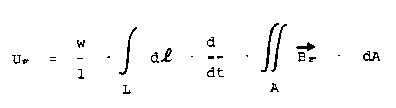
Die Messspulen 6,7 sind für den Fehlerstrom die Induktionsspulen, die in der radialen Richtung des Blechpakets unterschiedliche magnetische Induktionen BF des Fehlerstromes messen. Dadurch entsteht bei einem Blechschluss 8 eine Phasenverschiebung Δα zwischen den Spannungen der Messspulen 6,7 (Zeigerdiagramme in Fig. 4 und 5).Compared to the traditional iron sheet control with nominal yoke induction, which registers the heating of the sheet metal closings ("hot spots") (infrared camera, manual scanning), this method uses a
The measuring coils 6, 7 are the induction coils for the fault current, which measure different magnetic induction B F of the fault current in the radial direction of the laminated core. This results in a phase shift Δα between the voltages of the measuring coils 6, 7 (pointer diagrams in FIGS. 4 and 5) in the case of a sheet metal connection 8.
Die vom Fehlerstrom verursachten Phasenverschiebungen der Messspannungen sind von der Grösse und der Streckenlänge des Blechschlussstromes abhängig. Die Spannungen der Messpulen 6,7 werden verstärkt und mit einem Phasendetektor 9 wird die Phasenwinkelabweichung Δα der Messspannungen und/oder die Amplitudenänderung Δφ ermittelt (Fig. 6).The phase shifts of the measuring voltages caused by the fault current depend on the size and the length of the section current of the sheet metal. The voltages of the measuring coils 6, 7 are amplified and the phase angle deviation Δα of the measuring voltages and / or the amplitude change Δφ is determined with a phase detector 9 (FIG. 6).
Die vorzugsweise in einem fahrbaren Träger 10 eingebauten Messspulen 6,7 bewegen sich mittels Seiltrieb und eines Antriebsmotors 11 entlang der Nuten von einem Ende bis zum anderen Endes des Eisenblechpakets 1. Ein mit dem Antriebsmotor 11 gekuppelter Dreh- oder Weggeber 12 erlaubt es, die axiale Position des Trägers und damit der Messspulenanordnung 5 zu erfassen.The measuring coils 6, 7, which are preferably installed in a mobile carrier 10, move by means of a cable drive and a
Die durch Blechströme hervorgerufenen Phasenabweichungen Δα, und/oder Amplitudenänderungen Δφ der Messspannungen werden mit einem X-Y schreiber 13, als eine Serie von Linien, eine für jede Nut, registriert.The phase deviations Δα caused by sheet currents and / or amplitude changes Δφ of the measuring voltages are recorded with an
Die registrierten Signale entlang der Nuten werden mit den Signalen, die den Blechströmen entsprechen, verglichen. Eine Schleife 14 aus einem dünnen Leiter mit der Breite des Blechschlusses 16 wird an den Zahnoberfläche 15 befestigt und mit einem dem Blechschlussstrom entsprechenden Strom gespeist (Fig. 5).The registered signals along the grooves are compared with the signals that correspond to the sheet currents. A
Die Einspeisung des Blechschlussstromes erfolgt über den Autotransformator 3 aus dem Netz. Die Blechschlussströme von kurzgeschlossenen Blechen sind aus den bekannten Spannungswerten zwischen den Blechen und der Impedanz der einzelnen Bleche definiert. Das Signal der Messspulen (Δα) wird dann mit und ohne diesen Schleifenstrom registriert (ΔαE) und mit dem des Blechschlussstromes (ΔαF) verglichen (Fig. 7).The sheet metal short-circuit current is fed in via the autotransformer 3 from the network. The short-circuit currents of short-circuited sheets are defined from the known voltage values between the sheets and the impedance of the individual sheets. The signal from the measuring coils (Δα) is then registered with and without this loop current (Δα E ) and compared with that of the short-circuit current (Δα F ) (FIG. 7).
Anstelle eines Seiltriebes kann der Träger auch als flache Selbstfahr-Lafette ausgebildet werden, wobei entsprechend Fig.6 deren Antriebsmotor mit einem Weg- oder Umdrehungsgeber zur Erfassung des zurückgelegten Weges gekuppelt ist.Instead of a cable drive, the carrier can also be designed as a flat self-propelled mount, the drive motor of which, according to FIG. 6, being coupled to a displacement or rotation sensor for detecting the distance traveled.
Das beschriebene Verfahren ermöglicht bei elektrischen Maschinen eine Statorblechkontrolle auch mit eingebautem Rotor. Dabei muss der Rotor einer Seite der Maschine vollständig gegen Erde isoliert sein, was bei grossen Generatoren üblich ist.The described method enables a stator sheet inspection on electrical machines even with a built-in rotor. The rotor on one side of the machine must be completely insulated from earth, which is common with large generators.
Eine auf beiden Maschinenseiten nicht isolierte Welle wäre wie eine sekundär kurzgeschlossene Wicklung, in welcher wegen guter magnetischer Koppelung einige hundert Ampere bei schwacher Erregung fliessen können. Eine nicht vorhandene Isolation der Welle auf einer Maschinenseite ist durch die Messung des Wellenstromes mit einer Rogowski Spule und Wellenspannung gegen Erde am nichtantriebsseitigen Ende der Maschine und durch starke Erhöhung der für die Magnetisierung des Statorpakets benötigen Amperewindungen bemerkbar.A shaft that is not insulated on both sides of the machine would be like a secondary short-circuited winding, in which a few hundred amperes can flow with low excitation due to good magnetic coupling. A non-existent insulation of the shaft on one machine side is noticeable by measuring the shaft current with a Rogowski coil and shaft voltage against earth at the non-drive end of the machine and by greatly increasing the ampere windings required for the magnetization of the stator package.
Die Aufmagnetisierung des Statorpakets bei maschinen mit eingebautem Rotor, insbesondere bei grossen Turbomaschinen, erfolgt deshalb vorzugsweise aus einer stromstarken Speisequelle, die zwischen beiden Maschinenseiten an der isolierten Welle angeschlossen ist.The magnetization of the stator package in machines with a built-in rotor, in particular in large turbo machines, is therefore preferably carried out from a high-current feed source which is connected to the insulated shaft between the two machine sides.
Claims (7)
- Method for testing laminated cores (1) of electrical machines for cross-over shorts, in which the laminated core (1) is magnetized by an auxiliary coil (2) and the iron surface is probed by an assembly of measuring coils (MS1, MS2) connected to a meter (9), characterized in that a fluxgate magnetometer, comprising at least two electrically separated, radially spaced apart, but mechanically joined measuring coils (6, 7), is used to determine the radial distribution of the magnetic field due to the cross-over short-circuit current (IF) from the phase difference and/or the amplitude variation of the voltages (UM1, UM2) induced in the two measuring coils (6, 7).
- Method according to Claim 1, characterized in that the phase deviation (Δα) of the signals from the measuring coils (6, 7) is determined by a phase detector (9).
- Method according to Claim 1, characterized in that the amplitude difference (Δφ) of the signals from the measuring coils (6, 7), is detected by a recording device (13).
- Method according to one of Claims 1-3, characterized in that the recorded signals are compared with signals corresponding to cross-over short-circuit currents, whereby a loop (14) of the sheet width is fixed on the iron laminate surface (15) and fed with the corresponding cross-over short-circuit current.
- Method according to one of Claims 1-4, characterized in that the measuring coils (6, 7) are arranged on a mount (10) and transported by a drive motor (11) along the iron laminated core (1) from one end to the other.
- Method according to one of Claims 1-5, characterized by the magnetization of the iron laminated core (1) being carried out by connecting through the rotor shaft a high-current supply across the insulated shaft between the two sides of the machine.
- Device for the implementation of the method according to Claim 1, characterized by an auxiliary coil (2) for magnetization of the laminated core (1), a measuring coil assembly (5) with two electrically separate, mechanically joined measuring coils (6, 7), a meter (9) connected to the measuring coils which serves to detect the phase-angle deviation and/or amplitude variations of the voltages (UM1 UM2) induced in the measuring coils, as well as a recorder (13) connected to the meter.
Priority Applications (1)
| Application Number | Priority Date | Filing Date | Title |
|---|---|---|---|
| AT89109130T ATE102354T1 (en) | 1988-05-30 | 1989-05-20 | METHOD AND EQUIPMENT FOR CHECKING LAMINATED SHEET IRON PACKAGES FOR SHEET METAL LOCKS. |
Applications Claiming Priority (2)
| Application Number | Priority Date | Filing Date | Title |
|---|---|---|---|
| CH2043/88 | 1988-05-30 | ||
| CH2043/88A CH676526A5 (en) | 1988-05-30 | 1988-05-30 |
Publications (3)
| Publication Number | Publication Date |
|---|---|
| EP0344558A2 EP0344558A2 (en) | 1989-12-06 |
| EP0344558A3 EP0344558A3 (en) | 1992-04-15 |
| EP0344558B1 true EP0344558B1 (en) | 1994-03-02 |
Family
ID=4224607
Family Applications (1)
| Application Number | Title | Priority Date | Filing Date |
|---|---|---|---|
| EP89109130A Expired - Lifetime EP0344558B1 (en) | 1988-05-30 | 1989-05-20 | Method and apparatus for detecting short circuits in stacks of iron plates |
Country Status (7)
| Country | Link |
|---|---|
| US (1) | US4996486A (en) |
| EP (1) | EP0344558B1 (en) |
| JP (1) | JP3119854B2 (en) |
| CN (1) | CN1012286B (en) |
| AT (1) | ATE102354T1 (en) |
| CH (1) | CH676526A5 (en) |
| DE (1) | DE58907060D1 (en) |
Cited By (1)
| Publication number | Priority date | Publication date | Assignee | Title |
|---|---|---|---|---|
| WO2010040767A1 (en) * | 2008-10-08 | 2010-04-15 | Alstom Technology Ltd. | Method and device for detecting short-circuits in the stator core of electric machines |
Families Citing this family (41)
| Publication number | Priority date | Publication date | Assignee | Title |
|---|---|---|---|---|
| EP0482229B1 (en) * | 1990-10-22 | 1994-08-10 | Asea Brown Boveri Ag | Device for monitoring partial discharges in winding elements of an electric machine |
| US5321362A (en) * | 1992-09-15 | 1994-06-14 | Westinghouse Electric Corp. | Digital filtering of EL CID data |
| US5365166A (en) * | 1993-02-08 | 1994-11-15 | Westinghouse Electric Corporation | System and method for testing electrical generators |
| FR2762157B1 (en) * | 1997-04-09 | 2003-06-20 | Electricite De France | METHOD AND DEVICE FOR EXAMINING THE STATUS OF INSULATION OF SHEETS FROM A STACK IN AN ELECTRIC MACHINE |
| US5990688A (en) * | 1998-01-09 | 1999-11-23 | Hydro-Quebec | Apparatus and method for evaluation a condition of a magnetic circuit of an electric machine |
| GB9901101D0 (en) * | 1999-01-19 | 1999-03-10 | British Nuclear Fuels Plc | Proximity sensor |
| US6469504B1 (en) * | 2000-07-28 | 2002-10-22 | General Electric Company | Method and system for detecting core faults |
| US6489781B1 (en) | 2001-06-07 | 2002-12-03 | General Electric Company | Method and system for detecting core faults |
| PT1430297E (en) * | 2001-09-24 | 2006-11-30 | Alstom Technology Ltd | Method and device for controlling laminated steel sheet stacks of electrical machines in a view to detect steel sheet short-circuits |
| US6815957B2 (en) | 2001-09-24 | 2004-11-09 | Alstom (Switzerland) Ltd | Method and device for inspecting laminated iron cores of electrical machines for interlamination shorts |
| US6756788B2 (en) * | 2001-10-16 | 2004-06-29 | General Electric Company | Laminated core contact detection method and system |
| GB2382878B (en) * | 2001-12-04 | 2005-09-07 | Adwel Internat Ltd | A method and apparatus for testing laminated cores of electrical machines |
| US6794884B2 (en) | 2002-05-10 | 2004-09-21 | General Electric Company | Method and system for evaluating core stack pressure |
| US6791351B2 (en) * | 2002-06-28 | 2004-09-14 | Siemens Westinghouse Power Corporation | Electromagnetic stator insulation flaw detector |
| US6922060B1 (en) * | 2002-07-23 | 2005-07-26 | Alstom Technology Ltd. | Method for detecting partial conductor short circuits, and device for performing and using the method |
| US7208971B2 (en) * | 2002-10-15 | 2007-04-24 | General Electric Company | Manual probe carriage system and method of using the same |
| US6847224B2 (en) * | 2002-10-15 | 2005-01-25 | General Electric Company | Test probe |
| US6927598B2 (en) * | 2002-10-15 | 2005-08-09 | General Electric Company | Test probe for electrical devices having low or no wedge depression |
| DE10250194A1 (en) | 2002-10-28 | 2004-05-13 | OCé PRINTING SYSTEMS GMBH | Method and device for controlling an electrographic printer or copier |
| US6876222B2 (en) | 2002-11-12 | 2005-04-05 | Siemens Westinghouse Power Corporation | Automated stator insulation flaw inspection tool and method of operation |
| US6873152B2 (en) * | 2002-12-30 | 2005-03-29 | General Electric Company | Differential sensor apparatus and method for laminated core fault detection |
| EP1601985B1 (en) * | 2003-03-12 | 2007-11-28 | Siemens Aktiengesellschaft | Laminated core testing device |
| DE602004007735T2 (en) * | 2003-10-03 | 2008-04-10 | General Electric Co. | Probe with adjustable parts |
| US20050218906A1 (en) * | 2004-03-31 | 2005-10-06 | Younsi Abdelkrim K | System and method for monitoring of insulation condition |
| US7042229B2 (en) * | 2004-03-31 | 2006-05-09 | General Electric Company | System and method for on line monitoring of insulation condition for DC machines |
| US7466126B2 (en) * | 2004-07-12 | 2008-12-16 | General Electric Company | Universal sensor probe with adjustable members configured to fit between a plurality of slot openings of varying widths |
| EP2113780B1 (en) * | 2004-10-26 | 2011-01-05 | TSK Electronica y Electricidad, S.A. | Squirrel-cage asynchronous motor and fault-detection method therefor |
| RU2272245C1 (en) * | 2004-10-26 | 2006-03-20 | ЗАО "Электротехнические системы 1" | Method for measuring axial coordinate of sensor during control of isolation of sheets of charged cores of electric machines and device for realization of said method |
| RU2323448C2 (en) * | 2006-03-10 | 2008-04-27 | ЗАО "Электротехнические системы 1" | Method for monitoring of insulation of sheets of stator laminated cores in motors and generators and device for its realization |
| CN101932948B (en) * | 2007-12-07 | 2014-07-30 | 阿尔斯通技术有限公司 | Method for detection of interlaminar sheet short circuits in the stator sheet core of electromachines |
| US8508220B2 (en) * | 2011-02-11 | 2013-08-13 | Siemens Energy, Inc. | Fault detection for laminated core |
| US8564284B2 (en) * | 2011-02-11 | 2013-10-22 | Siemens Energy, Inc. | Fault detection for laminated core |
| CN102355090B (en) * | 2011-10-20 | 2013-02-27 | 清华大学 | Exploring coil arrangement method simultaneously reflecting electric generator stator and rotor internal short circuits |
| EP2602632A1 (en) * | 2011-12-06 | 2013-06-12 | Alstom Technology Ltd. | Method for ascertaining a short-circuit in a stator core |
| US9658192B2 (en) | 2012-01-23 | 2017-05-23 | Siemens Corporation | Insulation defect detection of high voltage generator stator core |
| US8829769B1 (en) | 2012-11-09 | 2014-09-09 | Dantam K. Rao | Coated keybar to protect electric machines |
| EP2746795B1 (en) * | 2012-12-20 | 2015-10-07 | Alstom Technology Ltd | Device and method for measuring the magnetic field in the air-gap of an electric machine |
| CN103293430B (en) * | 2013-05-08 | 2015-06-24 | 南车戚墅堰机车有限公司 | Method for detecting short-circuit fault occurring between iron cores of main transformer with stacked iron cores |
| EP2816365A1 (en) * | 2013-06-21 | 2014-12-24 | Siemens Aktiengesellschaft | Method for testing laminated core of a generator |
| EP3106890B1 (en) * | 2015-06-19 | 2025-08-13 | Arabelle Solutions France | Method for measuring a stator core of an electric machine and measuring device |
| CN108446399B (en) * | 2018-03-29 | 2021-07-30 | 重庆大学 | A dynamic storage optimization method for structured massive real-time data |
Family Cites Families (9)
| Publication number | Priority date | Publication date | Assignee | Title |
|---|---|---|---|---|
| GB1200146A (en) * | 1967-08-17 | 1970-07-29 | Friedrich M O Foerster | Measuring magnetic fields |
| AU3837372A (en) * | 1971-02-01 | 1973-08-02 | Automation Industries, Inc | Eddy current nondestructive testing system |
| DE3068908D1 (en) * | 1979-12-07 | 1984-09-13 | Thorburn Technics Int | Eddy current inspection apparatus and probe |
| US4573012A (en) * | 1983-02-14 | 1986-02-25 | General Electric Company | Method and apparatus for measuring core loss of a laminated ferromagnetic structure |
| US4649343A (en) * | 1983-12-27 | 1987-03-10 | The Babcock & Wilcox Company | Electromagnetic flux leakage inspection system for ferromagnetic tubes |
| US4631533A (en) * | 1984-06-15 | 1986-12-23 | Westinghouse Electric Corp. | Display of eddy current detector data |
| FR2570501B1 (en) * | 1984-09-20 | 1987-12-18 | Siderurgie Fse Inst Rech | METHOD FOR THE DETECTION OF SURFACE FAULTS BY EDGE CURRENTS AND DEVICE IMPLEMENTING THIS METHOD |
| US4823082A (en) * | 1986-02-18 | 1989-04-18 | Kabushiki Kaisha Kobe Seiko Sho | Signal processing method for an electromagnetic induction test |
| US4803563A (en) * | 1987-09-02 | 1989-02-07 | Westinghouse Electric Corp. | Rotor-in-stator examination magnetic carriage and positioning apparatus |
-
1988
- 1988-05-30 CH CH2043/88A patent/CH676526A5/de not_active IP Right Cessation
-
1989
- 1989-05-20 DE DE89109130T patent/DE58907060D1/en not_active Expired - Lifetime
- 1989-05-20 EP EP89109130A patent/EP0344558B1/en not_active Expired - Lifetime
- 1989-05-20 AT AT89109130T patent/ATE102354T1/en not_active IP Right Cessation
- 1989-05-30 US US07/358,638 patent/US4996486A/en not_active Expired - Lifetime
- 1989-05-30 CN CN89103797A patent/CN1012286B/en not_active Expired
- 1989-05-30 JP JP01134830A patent/JP3119854B2/en not_active Expired - Lifetime
Non-Patent Citations (1)
| Title |
|---|
| ELIN-Zeitschrift 1984,Heft 1/2,Seite 58 * |
Cited By (2)
| Publication number | Priority date | Publication date | Assignee | Title |
|---|---|---|---|---|
| WO2010040767A1 (en) * | 2008-10-08 | 2010-04-15 | Alstom Technology Ltd. | Method and device for detecting short-circuits in the stator core of electric machines |
| CH699666A1 (en) * | 2008-10-08 | 2010-04-15 | Alstom Technology Ltd | Method and device for the detection of short circuits in the stator laminated core of electric machines. |
Also Published As
| Publication number | Publication date |
|---|---|
| DE58907060D1 (en) | 1994-04-07 |
| EP0344558A3 (en) | 1992-04-15 |
| ATE102354T1 (en) | 1994-03-15 |
| CH676526A5 (en) | 1991-01-31 |
| EP0344558A2 (en) | 1989-12-06 |
| JPH0225766A (en) | 1990-01-29 |
| CN1012286B (en) | 1991-04-03 |
| CN1038169A (en) | 1989-12-20 |
| US4996486A (en) | 1991-02-26 |
| JP3119854B2 (en) | 2000-12-25 |
Similar Documents
| Publication | Publication Date | Title |
|---|---|---|
| EP0344558B1 (en) | Method and apparatus for detecting short circuits in stacks of iron plates | |
| DE3789848T2 (en) | Magnetic leakage flux sensor for non-destructive testing. | |
| EP0391181B1 (en) | Arrangement for detecting short circuit contacts in the rotor windings of electric motors | |
| EP2331980B1 (en) | Method and device for detecting short-circuits in the stator core of electric machines | |
| DE102006002552B4 (en) | Manual probe carrier system | |
| DE1473696B2 (en) | DEVICE FOR NON-DESTRUCTIVE MATERIAL TESTING | |
| EP2215490B1 (en) | Method for detection of interlaminar sheet short circuits in the stator sheet core of electromachines | |
| CH696778A5 (en) | Probe. | |
| DE102011101480B4 (en) | Converter tester and method of testing a feedthrough current transformer | |
| Ushakov et al. | Diagnostics of High-Voltage Equipment by Defectography Methods | |
| DE684052C (en) | Device for determining the transmission ratio of power transformers | |
| US3439265A (en) | Apparatus for suppressing interference currents in a measuring circuit by bypassing the interference currents around a branch of the measuring circuit through the suppressing means | |
| DE2455007B2 (en) | PROCEDURE FOR LOCATING DEFECTIVE INSULATION ON ELECTRICAL CABLES | |
| AT389176B (en) | MEASURING ARRANGEMENT FOR DETECTING AN IRON | |
| DE3206598A1 (en) | Arrangement for measuring and monitoring asymmetries in rotating electrical induction machines | |
| DE2644253C3 (en) | Device for testing a winding for interturn or short-circuit | |
| EP1430297B1 (en) | Method and device for controlling laminated steel sheet stacks of electrical machines in a view to detect steel sheet short-circuits | |
| DE833079C (en) | Measuring arrangement with cathode ray oscilloscope for error messages during the shock test, especially when testing transformer windings etc. like | |
| DE1613886A1 (en) | Device for monitoring bearing currents in electrical machines, in particular high power | |
| DE3234328C2 (en) | ||
| DE2039756A1 (en) | Arrangement for measuring the arc power and / or star voltage in the line of three-phase arc furnaces | |
| DE1448760C (en) | Use of a Hall plate to determine the deflection of an object with a magnetic field from a normal position | |
| DE704555C (en) | Arrangement for checking the connection of a three-phase current meter switched according to the two-watt meter method to the associated transducer with the aid of devices for measuring currents and voltages and for displaying the directions of rotating fields | |
| DE608533C (en) | Method for measuring small loss angles by means of a compensation method | |
| DE1788153B2 (en) | Arrangement for the detection of double earth and winding faults in the excitation winding of an electrical synchronous machine |
Legal Events
| Date | Code | Title | Description |
|---|---|---|---|
| PUAI | Public reference made under article 153(3) epc to a published international application that has entered the european phase |
Free format text: ORIGINAL CODE: 0009012 |
|
| AK | Designated contracting states |
Kind code of ref document: A2 Designated state(s): AT CH DE FR GB IT LI |
|
| PUAL | Search report despatched |
Free format text: ORIGINAL CODE: 0009013 |
|
| AK | Designated contracting states |
Kind code of ref document: A3 Designated state(s): AT CH DE FR GB IT LI |
|
| 17P | Request for examination filed |
Effective date: 19920903 |
|
| 17Q | First examination report despatched |
Effective date: 19921029 |
|
| GRAA | (expected) grant |
Free format text: ORIGINAL CODE: 0009210 |
|
| AK | Designated contracting states |
Kind code of ref document: B1 Designated state(s): AT CH DE FR GB IT LI |
|
| REF | Corresponds to: |
Ref document number: 102354 Country of ref document: AT Date of ref document: 19940315 Kind code of ref document: T |
|
| REF | Corresponds to: |
Ref document number: 58907060 Country of ref document: DE Date of ref document: 19940407 |
|
| ITF | It: translation for a ep patent filed | ||
| GBT | Gb: translation of ep patent filed (gb section 77(6)(a)/1977) |
Effective date: 19940516 |
|
| ET | Fr: translation filed | ||
| PLBE | No opposition filed within time limit |
Free format text: ORIGINAL CODE: 0009261 |
|
| STAA | Information on the status of an ep patent application or granted ep patent |
Free format text: STATUS: NO OPPOSITION FILED WITHIN TIME LIMIT |
|
| 26N | No opposition filed | ||
| REG | Reference to a national code |
Ref country code: GB Ref legal event code: IF02 |
|
| REG | Reference to a national code |
Ref country code: CH Ref legal event code: PUE Owner name: ASEA BROWN BOVERI AG TRANSFER- ALSTOM |
|
| REG | Reference to a national code |
Ref country code: GB Ref legal event code: 732E |
|
| REG | Reference to a national code |
Ref country code: FR Ref legal event code: CD Ref country code: FR Ref legal event code: CA |
|
| REG | Reference to a national code |
Ref country code: FR Ref legal event code: TP |
|
| PGFP | Annual fee paid to national office [announced via postgrant information from national office to epo] |
Ref country code: DE Payment date: 20080523 Year of fee payment: 20 Ref country code: CH Payment date: 20080515 Year of fee payment: 20 |
|
| PGFP | Annual fee paid to national office [announced via postgrant information from national office to epo] |
Ref country code: AT Payment date: 20080515 Year of fee payment: 20 |
|
| PGFP | Annual fee paid to national office [announced via postgrant information from national office to epo] |
Ref country code: IT Payment date: 20080527 Year of fee payment: 20 |
|
| PGFP | Annual fee paid to national office [announced via postgrant information from national office to epo] |
Ref country code: GB Payment date: 20080522 Year of fee payment: 20 |
|
| REG | Reference to a national code |
Ref country code: CH Ref legal event code: PL |
|
| REG | Reference to a national code |
Ref country code: GB Ref legal event code: PE20 Expiry date: 20090519 |
|
| PG25 | Lapsed in a contracting state [announced via postgrant information from national office to epo] |
Ref country code: GB Free format text: LAPSE BECAUSE OF EXPIRATION OF PROTECTION Effective date: 20090519 |
|
| PGFP | Annual fee paid to national office [announced via postgrant information from national office to epo] |
Ref country code: FR Payment date: 20080425 Year of fee payment: 20 |