EP0344532B1 - Sealing device of the bearing of a rotating shaft with its drive unit - Google Patents
Sealing device of the bearing of a rotating shaft with its drive unit Download PDFInfo
- Publication number
- EP0344532B1 EP0344532B1 EP89108965A EP89108965A EP0344532B1 EP 0344532 B1 EP0344532 B1 EP 0344532B1 EP 89108965 A EP89108965 A EP 89108965A EP 89108965 A EP89108965 A EP 89108965A EP 0344532 B1 EP0344532 B1 EP 0344532B1
- Authority
- EP
- European Patent Office
- Prior art keywords
- housing
- shaft
- arrangement according
- pressure
- sealing element
- Prior art date
- Legal status (The legal status is an assumption and is not a legal conclusion. Google has not performed a legal analysis and makes no representation as to the accuracy of the status listed.)
- Revoked
Links
Images
Classifications
-
- F—MECHANICAL ENGINEERING; LIGHTING; HEATING; WEAPONS; BLASTING
- F16—ENGINEERING ELEMENTS AND UNITS; GENERAL MEASURES FOR PRODUCING AND MAINTAINING EFFECTIVE FUNCTIONING OF MACHINES OR INSTALLATIONS; THERMAL INSULATION IN GENERAL
- F16J—PISTONS; CYLINDERS; SEALINGS
- F16J15/00—Sealings
- F16J15/50—Sealings between relatively-movable members, by means of a sealing without relatively-moving surfaces, e.g. fluid-tight sealings for transmitting motion through a wall
-
- F—MECHANICAL ENGINEERING; LIGHTING; HEATING; WEAPONS; BLASTING
- F04—POSITIVE - DISPLACEMENT MACHINES FOR LIQUIDS; PUMPS FOR LIQUIDS OR ELASTIC FLUIDS
- F04D—NON-POSITIVE-DISPLACEMENT PUMPS
- F04D13/00—Pumping installations or systems
- F04D13/02—Units comprising pumps and their driving means
- F04D13/021—Units comprising pumps and their driving means containing a coupling
- F04D13/024—Units comprising pumps and their driving means containing a coupling a magnetic coupling
-
- F—MECHANICAL ENGINEERING; LIGHTING; HEATING; WEAPONS; BLASTING
- F04—POSITIVE - DISPLACEMENT MACHINES FOR LIQUIDS; PUMPS FOR LIQUIDS OR ELASTIC FLUIDS
- F04D—NON-POSITIVE-DISPLACEMENT PUMPS
- F04D13/00—Pumping installations or systems
- F04D13/02—Units comprising pumps and their driving means
- F04D13/06—Units comprising pumps and their driving means the pump being electrically driven
- F04D13/0606—Canned motor pumps
- F04D13/0633—Details of the bearings
-
- F—MECHANICAL ENGINEERING; LIGHTING; HEATING; WEAPONS; BLASTING
- F04—POSITIVE - DISPLACEMENT MACHINES FOR LIQUIDS; PUMPS FOR LIQUIDS OR ELASTIC FLUIDS
- F04D—NON-POSITIVE-DISPLACEMENT PUMPS
- F04D29/00—Details, component parts, or accessories
- F04D29/06—Lubrication
- F04D29/061—Lubrication especially adapted for liquid pumps
-
- F—MECHANICAL ENGINEERING; LIGHTING; HEATING; WEAPONS; BLASTING
- F04—POSITIVE - DISPLACEMENT MACHINES FOR LIQUIDS; PUMPS FOR LIQUIDS OR ELASTIC FLUIDS
- F04D—NON-POSITIVE-DISPLACEMENT PUMPS
- F04D29/00—Details, component parts, or accessories
- F04D29/08—Sealings
- F04D29/10—Shaft sealings
- F04D29/12—Shaft sealings using sealing-rings
- F04D29/126—Shaft sealings using sealing-rings especially adapted for liquid pumps
- F04D29/128—Shaft sealings using sealing-rings especially adapted for liquid pumps with special means for adducting cooling or sealing fluid
-
- B—PERFORMING OPERATIONS; TRANSPORTING
- B01—PHYSICAL OR CHEMICAL PROCESSES OR APPARATUS IN GENERAL
- B01F—MIXING, e.g. DISSOLVING, EMULSIFYING OR DISPERSING
- B01F35/00—Accessories for mixers; Auxiliary operations or auxiliary devices; Parts or details of general application
- B01F35/30—Driving arrangements; Transmissions; Couplings; Brakes
- B01F2035/35—Use of other general mechanical engineering elements in mixing devices
- B01F2035/351—Sealings
-
- Y—GENERAL TAGGING OF NEW TECHNOLOGICAL DEVELOPMENTS; GENERAL TAGGING OF CROSS-SECTIONAL TECHNOLOGIES SPANNING OVER SEVERAL SECTIONS OF THE IPC; TECHNICAL SUBJECTS COVERED BY FORMER USPC CROSS-REFERENCE ART COLLECTIONS [XRACs] AND DIGESTS
- Y10—TECHNICAL SUBJECTS COVERED BY FORMER USPC
- Y10S—TECHNICAL SUBJECTS COVERED BY FORMER USPC CROSS-REFERENCE ART COLLECTIONS [XRACs] AND DIGESTS
- Y10S277/00—Seal for a joint or juncture
- Y10S277/927—Seal including fluid pressure differential feature
-
- Y—GENERAL TAGGING OF NEW TECHNOLOGICAL DEVELOPMENTS; GENERAL TAGGING OF CROSS-SECTIONAL TECHNOLOGIES SPANNING OVER SEVERAL SECTIONS OF THE IPC; TECHNICAL SUBJECTS COVERED BY FORMER USPC CROSS-REFERENCE ART COLLECTIONS [XRACs] AND DIGESTS
- Y10—TECHNICAL SUBJECTS COVERED BY FORMER USPC
- Y10S—TECHNICAL SUBJECTS COVERED BY FORMER USPC CROSS-REFERENCE ART COLLECTIONS [XRACs] AND DIGESTS
- Y10S422/00—Chemical apparatus and process disinfecting, deodorizing, preserving, or sterilizing
- Y10S422/903—Radioactive material apparatus
Definitions
- the invention relates to an arrangement for sealing the bearing and the drive element of a rotating shaft, in particular for agitators and / or pump impellers.
- sealless pump represents a combination of a centrifugal pump and a magnetic clutch. This is a pump with no connection on the shaft between the space containing the medium and the atmosphere, ie the space containing the medium is completely encapsulated.
- sealless pumps are usually used for pumping pure liquids, since the medium forms the lubricant source for the slide bearing of the inner rotor. Contamination can be filtered out before entering the bearing and the magnetic area. If the contaminants are sticky and cannot be filtered out, then a stream of a pure fluid that is compatible with the medium can be independently injected at one point, which then reaches the pump chamber.
- a rotary pump with a coupling part can be found in document WO 88/09874 within the meaning of Art. 54 (3) EPC.
- This rotary pump should be designed so that quickly wearing parts can be easily replaced without having to throw away expensive and not so wear-prone parts, especially the drive. Furthermore, the fact that the pump parts coming into contact with the medium can be replaced and eliminated quickly and easily to avoid contamination and the drive part can be reused should also be taken into account in the design.
- This pump comprises a coupling part and a drive part.
- the coupling member may include seals which prevent fluid from entering parts of the coupling member or which prevent lubricant or coolant from entering the impeller part.
- the drive member may also include seals that hold the lubricant and coolant in the predetermined location.
- either a one-way seal or impermeable seals can be provided which prevent the coolant / lubricant from moving away either in one or both directions in the coupling part.
- the clutch housing and the drive housing can be provided completely separate from one another in order to make it impossible for the drive device to be exposed to fluid, which could occur, for example, if the seals in the pump wheel housing and in the clutch housing fail.
- the invention is therefore based on the object of an arrangement to provide the generic type, which enables an essentially leak-free seal of the agitator and / or the pump impeller in a structurally simple and operationally reliable manner.
- an arrangement for sealing the bearing and the drive element of a rotating shaft, in particular for agitators and / or pump impellers, is specified for this purpose, which is shown in claim 1.
- the mechanical seal seals the product space from the bearings and the drive element, while the hermetically sealing static sealing element hermetically seals the drive end of the agitator shaft and the drive element sitting on it.
- the dynamic mechanical seal effects a seal at a point with a relatively small pressure difference, so that the mechanical seal is durable and resistant.
- the sealing on the side with the greater pressure difference from the atmosphere, on the other hand, is provided by the static sealing element.
- a space is obtained between the static sealing element and the dynamic mechanical seal, which is formed by the housing interior, and in which the sensitive parts, such as bearings, clutch inner part and the like, can be accommodated in a protected manner.
- This housing interior is under a suitable fluid pressure, which is at least approximately the same, but preferably above the pressure in the product container.
- the drive element is expediently the inner part of a magnetic coupling, the outer part of which is driven by a suitable drive motor, such as an electric motor or a hydraulic motor, via a drive shaft.
- a suitable drive motor such as an electric motor or a hydraulic motor
- the cup-shaped static sealing element is installed between the inner coupling part and the outer coupling part of the magnetic coupling.
- the torque is transmitted by permanent magnets to the two coupling parts.
- the product space is expediently sealed by a gap between two very smooth surfaces which slide quickly onto one another and are acted upon by a differential pressure.
- the mechanical seal and the static sealing element offer a high level of security against leakage.
- the housing with the bearings for the rotating shaft between the mechanical seal and the static sealing element is preferably filled with a lubricant.
- the housing can be completely or only partially, for. B. approximately to the upper bearing, filled with the lubricating liquid, in the latter case a gas cushion, in particular made of nitrogen, is present above the level of the lubricating liquid, which pressurizes the lubricating liquid.
- the pressure of the gas or the lubricating liquid is preferably about 0 to about 3 bar above the pressure in the product container.
- Pumps for circulating the lubricating liquid and for dissipating the heat standing on the mechanical seal and on the drive element are advantageously arranged on a housing cooling on the shaft.
- the outer part of the magnetic coupling is expediently tightly enclosed by a hood which is provided with a blow-off pipe. If the cup-shaped sealing element is damaged, the contents can be discharged to an incinerator or a tank.
- the static sealing element can form the housing for a drive motor, which is possibly connected to the one shaft end via a gear.
- the drive motor and the transmission are then installed within the static sealing element.
- the lower bearing can be located in the product container, while the upper bearing is arranged in the area of the drive element.
- the mechanical seal can optionally also be arranged below the level of the product to be treated.
- the differential pressure at the mechanical seal is approximately 0 to 15% of the pressure in the product container.
- an agitator 10 with, for example, a vertical shaft 12, at the lower end of which an agitator 14, e.g. a stirring propeller with several stirring arms is attached.
- this product can be a toxic, a radioactive, an aggressive or an explosive medium or also a solid suspension, in which case a practically leak-free seal to the outside is required.
- the shaft 12 is rotatably supported radially and axially in bearings 18, 20, in particular roller bearings, the bearings 18, 20 in turn being installed and supported in a housing part 22, the so-called bearing lantern.
- the storage lantern 22 is fixed to the product container 16, e.g. by screws, not shown, connected, an annular seal 82 being arranged between these two parts.
- a hood 24 is placed, which is also firmly connected to the former by screws, with a seal, e.g., between the hood 24 and the bearing lantern 22.
- a sealing ring 74 is used, as will be explained in more detail.
- the torque is transmitted to the shaft 12 via a magnetic coupling 26, which consists of an outer coupling part 30 and an inner coupling part 28, the outer coupling part 30 on its inner wall and the inner coupling part 28 on its outer circumference being occupied with permanent magnets 32.
- the outer coupling part 30 is rotatably installed within the hood 24 and coupled to a drive shaft 34 which extends through the hood 24 to the outside and which in turn is coupled to a drive motor, not shown, for driving the outer coupling part 30. Between the drive shaft 34 and the hood 24 a sealing ring 80 is arranged.
- the inner coupling part 28 is fixedly connected to the stirrer shaft 12 or, as in the example shown, it is made in one piece with it.
- a static sealing element 36 is installed between the inner coupling part 28 and the outer coupling part 30, which has an approximately cup-shaped shape and which is provided at its lower open end in the figure with a radially outwardly directed collar 84 which is located between the bearing lantern 22 and the hood 24 arranged together with the seal 74 and clamped together by the two parts 22, 24, with which the sealing element 36 effects a static hermetic seal of the interior of the agitator to the outside.
- the sealing element 36 which in the illustrated embodiment forms the so-called containment shell of the magnetic coupling 26, consists, for example, made of a metal-free fiber composite material and it separates the pressure range of the agitator from the atmosphere. When using such a material, undesirable eddy currents are avoided in the contactless transmission of the torque from the outer coupling part 30 to the inner coupling part 28.
- the sealing element 36 can also consist of an electrically conductive material, in which case cooling is expediently used, as is provided in the embodiment shown and described.
- a mechanical seal is installed between the stirrer shaft 12 and the housing part 22, which is formed from a stationary ring 38 and a ring 40 rotating with the shaft 12.
- An annular seal 76 is seated between the stationary ring 38 and the housing 22, and a sealing ring 78 is likewise arranged between the ring 40 rotating with the shaft 12 and the shaft.
- the mutually facing end faces of the two rings 38 and 40 slide against one another during operation to form a very narrow gap and the two rings of the mechanical seal are pressed against one another by the differential pressure between the pressure in the product container 16 and the pressure in the interior 86 of the housing.
- the pressure in the interior of the product container 16 is e.g. by a pressure gauge 62 and the pressure in the interior 86 of the housing is e.g. measured by a manometer 60.
- the slide rings can be made of SiC, Si / SiC or carbon, which can be combined with each other depending on the application. Among other things, they can also be used for solid suspensions and also for the treatment of sticky and crusty products.
- the mechanical seal can also be below the level of the product to be treated, i.e. immersed in this, be arranged.
- the interior 86 of the agitator housing between the mechanical seal and the static sealing element can be completely filled with a gas, e.g. Nitrogen can be filled, which can be filled in and refilled via a line 58.
- a gas e.g. Nitrogen can be filled, which can be filled in and refilled via a line 58.
- the bearings 18 and 20 are dry running bearings, e.g. made of ceramic materials or plastics.
- the interior 86 is filled with a lubricating fluid, either completely or to the extent that the upper bearing 20 is just immersed in the lubricant.
- a neutral gas in particular nitrogen, is filled in above the level of the product-neutral lubricant and between the lubricant level and the cup-shaped sealing element 36 maintain a gas cushion under pressure, through which the lubricating liquid is pressurized.
- the pressure in the gas cushion and thus in the lubricating liquid is kept via line 58 from an external gas supply to about 0 to about 3 bar above the pressure in the product container 16. This is also the case when the interior space 86 of the housing is completely filled with gas or completely with lubricating liquid.
- the pressure in the interior 86 is thus at least equal to the pressure in the product container 16, but preferably somewhat higher, no product can penetrate into the interior 86 from the product container 16.
- the lubricant not only serves to lubricate the mechanical seal, but also to cool and dissipate the heat generated on the mechanical seal and, if applicable, on the magnetic coupling.
- pumps 42, 48 and 54 are arranged on the shaft.
- the pump 42 sits between the mechanical seal and the lower bearing 18, it rotates with the shaft 12 and sucks in the lubricant via axial channels and throws the latter radially outwards due to the centrifugal force.
- Two overflow channels 44 are formed in the housing 22, which connect the area of the interior space 86 below the bearing 18 to the area above the bearing 18. (Of course, only one such overflow channel 44 or more than two channels can be provided).
- An overflow channel 46 is also formed in the shaft 12, which connects the area of the inner space 86 above the bearing 18 with the area directly at the mechanical seal, as a result of which the lubricant is circulated from the mechanical seal 38, 40 via the pump 42 and the overflow channels 44 the area of the interior 86 above the bearing 18 and from there back through the overflow channel 46 to the mechanical seal.
- the upper end of the shaft or the inner coupling part 28 in the figure is also provided with a pump 48 in the form of a transverse bore in the inner coupling part 28 above the permanent magnets 32, from which transverse bore branches an axial bore 50 in the shaft 12 and runs downwards until below the upper bearing 20, where the axial bore 50 opens into the interior 86 of the housing via a short transverse bore 52.
- a further overflow channel 70 is formed in the bearing lantern 22, which opens into the interior 86 above and below the upper bearing 20. (Only one such overflow channel 70 is shown, but several can also be provided).
- the heat from the mechanical seal 38, 40 can thus be dissipated by the pump 42 and the heat from the magnetic coupling 26 can be dissipated by the pump 48.
- a pump wheel 54 On the shaft, there is also connected in a rotationally fixed manner in the area between the two bearings 18 and 20, a pump wheel 54, through which the lubricant is circulated in the interior 86 in order to transfer the heat it contains to a housing cooling 64.
- the housing in particular the bearing lantern 22, is provided with cooling channels, e.g. 64, to which a coolant, e.g. Cooling water, supplied and discharged via a drain line 68.
- a coolant e.g. Cooling water
- the lubricating liquid is supplied or refilled via line 56, and its pressure and thus the pressure in interior space 86 is measured by manometer 60.
- a refill pump (not shown) for the lubricant is switched on and / or if necessary the pressure of the gas cushion is increased and an alarm is triggered. If the leakage increases, the agitator switches off automatically.
- the agitator is also switched off.
- the leakage can be drained off via a line 72 for combustion, for exhaust gas scrubbing or into a safety tank.
- the static sealing element 36 can form the housing for a drive motor, which is optionally coupled to the upper end of the stirrer shaft 12 via a gear. In this case, the entire drive, including any gear required, is then installed within the static, hermetically sealing element 36.
- the lower bearing can also be arranged in the product container 16 and the upper bearing in the region of the drive element, the mechanical seal then being located between the two bearings.
- the shaft with its bearings 18, 20, which are sealed by the mechanical seal 38, 40 and the static sealing element 36, can be completely surrounded by the product to be treated.
Landscapes
- Engineering & Computer Science (AREA)
- General Engineering & Computer Science (AREA)
- Mechanical Engineering (AREA)
- Mechanical Sealing (AREA)
- Sealing Of Bearings (AREA)
- Sealing Devices (AREA)
- Sealing Using Fluids, Sealing Without Contact, And Removal Of Oil (AREA)
Abstract
Description
Die Erfindung bezieht sich auf eine Anordnung zur Abdichtung der Lagerung und des Antriebselementes einer rotierenden Welle, insbesondere für Rührwerke und/oder Pumpenlaufräder.The invention relates to an arrangement for sealing the bearing and the drive element of a rotating shaft, in particular for agitators and / or pump impellers.
Aus der Zeitschrift "World Pumps", April 1982, Seiten 175 bis 178, sind permanentmagnetische Antriebe für Pumpen und Rührwerke bekannt. Hierbei wird u.a. eine dichtungslose Pumpe beschrieben, welche eine Kombination aus einer Zentrifugalpumpe und einer magnetischen Kupplung darstellt. Hierbei handelt es sich um eine Pumpe mit keiner Verbindung an der Welle zwischen dem das Medium enthaltenden Raum und der Atmosphäre, d.h., der das Medium enthaltende Raum ist vollständig gekapselt. Üblicherweise werden derartige dichtungslose Pumpen zum Pumpen von reinen Flüssigkeiten eingesetzt, da das Medium die Schmiermittelquelle für das Gleitlager des inneren Rotors bildet. Verunreinigungen können hierbei vor dem Eintritt in das Lager und den Magnetbereich ausgefiltert werden. Wenn die Verunreinigungen klebrig sind und nicht ausgefiltert werden können, dann kann unabhängig ein Strom eines reinen Fluids, welches mit dem Medium kompatibel ist, an einer Stelle eingespritzt werden, welches dann zum Pumpenraum gelangt. Wenn dies nicht möglich ist, so bleibt noch als Lösung übrig, den Pumpenkreislauf vollständig von einem unabhängigen Schmiermittel/Kühlmittel-Kreislauf zu trennen, welcher seinen eigenen Vorratsbehälter, seine eigene Dosierpumpe und einen Wärmeübertrager hat. Hierbei ist eine statische, topfförmige Dichtung vorgesehen, welche von dem Spalttopf der Magnetkupplung gebildet wird. Da die Pumpe dichtungslos arbeiten soll, müssen die Lager für die Welle in unmittelbarer Nähe der Antriebsseite und der dort vorgesehenen statischen Dichtung angeordnet werden. Bei langen Wellen führt dies zu Lagerproblemen, und wenn die Lager weiter zur Mediumseite hin angeordnet werden, so ergeben sich Korrosionsprobleme, wenn beispielsweise Dampf aus dem das Medium enthaltenden Raum in die Lagerbereiche eindringt. Wenn hierbei ein unabhängiger Schmiermittel/Kühlmittelkreislauf vorhanden ist, so ist dieser als ein in sich geschlossenes System ohne Schnittstelle zur Welle und zum Pumpenraum anzusehen.Permanent magnetic drives for pumps and agitators are known from the magazine "World Pumps", April 1982, pages 175 to 178. Here, a sealless pump is described, which represents a combination of a centrifugal pump and a magnetic clutch. This is a pump with no connection on the shaft between the space containing the medium and the atmosphere, ie the space containing the medium is completely encapsulated. Such sealless pumps are usually used for pumping pure liquids, since the medium forms the lubricant source for the slide bearing of the inner rotor. Contamination can be filtered out before entering the bearing and the magnetic area. If the contaminants are sticky and cannot be filtered out, then a stream of a pure fluid that is compatible with the medium can be independently injected at one point, which then reaches the pump chamber. If this is not possible, the only solution left is to completely separate the pump circuit from an independent lubricant / coolant circuit, which has its own reservoir, its own metering pump and a heat exchanger. Here, a static, cup-shaped seal is provided, which is formed by the containment shell of the magnetic coupling. Since the pump is to work without a seal, the bearings for the shaft must be arranged in the immediate vicinity of the drive side and the static seal provided there. With long shafts, this leads to bearing problems, and if the bearings are arranged further towards the medium side, they result corrosion problems arise, for example, if steam penetrates from the space containing the medium into the storage areas. If an independent lubricant / coolant circuit is available, this should be viewed as a self-contained system without an interface to the shaft and the pump chamber.
Aus dem Dokument WO 88/09874 ist im Sinne von Art. 54(3) EPÜ eine Rotationspumpe mit einem Kupplungsteil zu entnehmen. Diese Rotationspumpe soll derart ausgelegt werden, daß sich schnell verschleißende Teile einfach auswechseln lassen, ohne daß man teure und nicht so sehr verschleißanfällige Teile, insbesondere des Antriebs wegwerfen muß. Ferner soll bei der Auslegung auch der Umstand berücksichtigt werden, daß die mit dem Medium in Berührung kommenden Pumpenteile zur Vermeidung von Kontaminierungen schnell und einfach für sich ausgewechselt und beseitigt werden können, und der Antriebsteil wiederverwendet werden kann. Diese Pumpe umfaßt ein Kupplungsteil und ein Antriebsteil. Das Kupplungsteil kann Dichtungen enthalten, welche verhindern, daß Fluid in Teile des Kupplungsteils eindringt, oder die verhindern, daß Schmiermittel oder Kühlmittel in den Pumpenradteil eindringt. Der Antriebsteil kann ebenfalls Dichtungen enthalten, welche das Schmiermittel und das Kühlmittel an der vorbestimmten Stelle halten. Ferner können entweder eine Einweg-Dichtung oder undurchlässige Dichtungen vorgesehen sein, welche eine Wegbewegung des Kühlmittels/Schmiermittels entweder in eine oder beide Richtungen im Kupplungsteil verhindern. Ferner können das Kupplungsgehäuse und das Antriebsgehäuse vollständig getrennt voneinander vorgesehen sein, um die Beaufschlagung der Antriebseinrichtung durch Fluid unmöglich zu machen, was beispielsweise auftreten könnte, wenn die Dichtungen im Pumpenradgehäuse und im Kupplungsgehäuse versagen.A rotary pump with a coupling part can be found in document WO 88/09874 within the meaning of Art. 54 (3) EPC. This rotary pump should be designed so that quickly wearing parts can be easily replaced without having to throw away expensive and not so wear-prone parts, especially the drive. Furthermore, the fact that the pump parts coming into contact with the medium can be replaced and eliminated quickly and easily to avoid contamination and the drive part can be reused should also be taken into account in the design. This pump comprises a coupling part and a drive part. The coupling member may include seals which prevent fluid from entering parts of the coupling member or which prevent lubricant or coolant from entering the impeller part. The drive member may also include seals that hold the lubricant and coolant in the predetermined location. Furthermore, either a one-way seal or impermeable seals can be provided which prevent the coolant / lubricant from moving away either in one or both directions in the coupling part. Furthermore, the clutch housing and the drive housing can be provided completely separate from one another in order to make it impossible for the drive device to be exposed to fluid, which could occur, for example, if the seals in the pump wheel housing and in the clutch housing fail.
Für Prozesse auf dem Gebiet der Kerntechnik und der chemischen Industrie werden Wellenabdichtungen gefordert, die zur Atmosphäre leckagefrei sein müssen.For processes in the field of nuclear technology and the chemical industry, shaft seals are required that must be leak-free to the atmosphere.
Der Erfindung liegt daher die Aufgabe zugrunde, eine Anordnung der gattungsgemäßen Art bereitzustellen, welche eine im wesentlichen leckagefreie Abdichtung des Rührwerks und/oder des Pumpenlaufrads auf konstruktiv einfache und betriebszuverlässige Weise ermöglicht.The invention is therefore based on the object of an arrangement to provide the generic type, which enables an essentially leak-free seal of the agitator and / or the pump impeller in a structurally simple and operationally reliable manner.
Nach der Erfindung wird hierzu eine Anordnung zur Abdichtung der Lagerung und des Antriebselements einer rotierenden Welle, insbesondere für Rührwerke und/oder Pumpenlaufräder angegeben, welche im Patentanspruch 1 wiedergegeben ist.According to the invention, an arrangement for sealing the bearing and the drive element of a rotating shaft, in particular for agitators and / or pump impellers, is specified for this purpose, which is shown in claim 1.
Bei der erfindungsgemäßen Anordnung dichtet die Gleitringdichtung den Produktraum gegenüber den Lagern und dem Antriebselement ab, während das hermetisch abdichtende statische Dichtelement das Antriebsende der Rührwelle und das auf ihr sitzende Antriebselement hermetisch nach außen abdichtet. Die dynamische Gleitringdichtung bewirkt eine Dichtung an einer Stelle mit einer relativ kleinen Druckdifferenz, so daß die Gleitringdichtung dauerhaft und wiederstandsfähig ist. Die Abdichtung auf der Seite mit der größeren Druckdifferenz gegenüber der Atmosphäre erfolgt hingegen durch das statische Dichtelement. Bei der erfindungsgemäßen Anordnung erhält man zwischen dem statischen Dichtelement und der dynamischen Gleitringdichtung einen Sperraum, welcher von dem Gehäuseinnenraum gebildet wird, und in welchem die empfindlichen Teile, wie Lager, Kupplungsinnenteil und dergleichen in geschützter Weise untergebracht werden können. Dieser Gehäuseinnenraum steht unter einem geeigneten Fluiddruck, der wenigstens etwa gleich, vorzugsweise aber über dem Druck im Produktbehälter liegt.In the arrangement according to the invention, the mechanical seal seals the product space from the bearings and the drive element, while the hermetically sealing static sealing element hermetically seals the drive end of the agitator shaft and the drive element sitting on it. The dynamic mechanical seal effects a seal at a point with a relatively small pressure difference, so that the mechanical seal is durable and resistant. The sealing on the side with the greater pressure difference from the atmosphere, on the other hand, is provided by the static sealing element. In the arrangement according to the invention, a space is obtained between the static sealing element and the dynamic mechanical seal, which is formed by the housing interior, and in which the sensitive parts, such as bearings, clutch inner part and the like, can be accommodated in a protected manner. This housing interior is under a suitable fluid pressure, which is at least approximately the same, but preferably above the pressure in the product container.
Zweckmäßigerweise ist das Antriebselement hierbei das Innenteil einer Magnetkupplung, deren Außenteil über eine Antriebswelle von einem geeigneten Antriebsmotor, wie einem Elektromotor oder einem Hydraulikmotor, angetrieben wird. Zwischen dem Innenkupplungsteil und dem Außenkupplungsteil der Magnetkupplung ist das beispielsweise topfförmig ausgebildete statische Dichtelement eingebaut.The drive element is expediently the inner part of a magnetic coupling, the outer part of which is driven by a suitable drive motor, such as an electric motor or a hydraulic motor, via a drive shaft. The cup-shaped static sealing element is installed between the inner coupling part and the outer coupling part of the magnetic coupling.
Die Drehmomentübertragung erfolgt durch Permanentmagnete an den beiden Kupplungsteilen.The torque is transmitted by permanent magnets to the two coupling parts.
Zweckmäßigerweise wird bei der Gleitringdichtung der Produktraum durch einen Spalt zweier sehr glatter Flächen abgedichtet, die schnell aufeinander gleiten und von einem Differenzdruck beaufschlagt werden.In the mechanical seal, the product space is expediently sealed by a gap between two very smooth surfaces which slide quickly onto one another and are acted upon by a differential pressure.
Die Gleitringdichtung und das statische Dichtelement bieten eine hohe Sicherheit gegen Leckage.The mechanical seal and the static sealing element offer a high level of security against leakage.
Vorzugsweise ist das Gehäuse mit den Lagern für die rotierende Welle zwischen der Gleitringdichtung und dem statischen Dichtelement mit einer Schmierflüssigkeit gefüllt.The housing with the bearings for the rotating shaft between the mechanical seal and the static sealing element is preferably filled with a lubricant.
Das Gehäuse kann hierbei vollständig oder nur teilweise, z. B. etwa bis zum oberen Lager, mit der Schmierflüssigkeit gefüllt sein, wobei im letzteren Fall oberhalb des Spiegels der Schmierflüssigkeit ein Gaspolster, insbesondere aus Stickstoff vorhanden ist, welches die Schmierflüssigkeit mit Druck beaufschlagt.The housing can be completely or only partially, for. B. approximately to the upper bearing, filled with the lubricating liquid, in the latter case a gas cushion, in particular made of nitrogen, is present above the level of the lubricating liquid, which pressurizes the lubricating liquid.
Es kann aber auch vorgesehen sein, das Gehäuse mit den Lagern für die rotierende Welle zwischen der Gleitringdichtung und dem statischen Dichtelement nur mit Gas, insbesondere Stickstoff, zu füllen, wobei in diesem Fall die Lager trocken laufen.But it can also be provided to fill the housing with the bearings for the rotating shaft between the mechanical seal and the static sealing element only with gas, in particular nitrogen, in which case the bearings run dry.
Der Druck des Gases bzw. der Schmierflüssigkeit liegt vorzugsweise etwa 0 bis etwa 3 bar über dem Druck im Produktbehälter.The pressure of the gas or the lubricating liquid is preferably about 0 to about 3 bar above the pressure in the product container.
Vorteilhafterweise sind auf der Welle Pumpen zur Umwälzung der Schmierflüssigkeit und zur Abfuhr der an der Gleitringdichtung und am Antriebselement stehenden Wärme an eine Gehäusekühlung angeordnet.Pumps for circulating the lubricating liquid and for dissipating the heat standing on the mechanical seal and on the drive element are advantageously arranged on a housing cooling on the shaft.
Das Außenteil der Magnetkupplung ist zweckmäßigerweise von einer Haube dicht umschlossen, die mit einem Abblasrohr versehen ist. Falls das topfförmige Dichtelement beschädigt werden sollte, kann der Inhalt zu einer Verbrennungsanlage oder einem Tank abgeleitet werden.The outer part of the magnetic coupling is expediently tightly enclosed by a hood which is provided with a blow-off pipe. If the cup-shaped sealing element is damaged, the contents can be discharged to an incinerator or a tank.
Das statische Dichtelement kann das Gehäuse für einen Antriebsmotor bilden, der ggf. über ein Getriebe mit dem einen Wellenende verbunden ist. Bei einer solchen Ausführungsform sind dann der Antriebsmotor und das Getriebe innerhalb des statischen Dichtelementes eingebaut.The static sealing element can form the housing for a drive motor, which is possibly connected to the one shaft end via a gear. In such an embodiment, the drive motor and the transmission are then installed within the static sealing element.
Nach einer weiteren Ausführungsform kann das untere Lager im Produktbehälter liegen, während das obere Lager im Bereich des Antriebselementes angeordnet ist.According to a further embodiment, the lower bearing can be located in the product container, while the upper bearing is arranged in the area of the drive element.
Die Gleitringdichtung kann ggf. auch unter dem Niveau des zu behandelnden Produktes angeordnet sein.The mechanical seal can optionally also be arranged below the level of the product to be treated.
Auch ist es möglich, die Welle mit ihren Lagern, die durch die Gleitringdichtung und das statische Dichtelement abgedichtet sind, so einzubauen, daß sie vollständig von dem Produkt umschlossen sind.It is also possible to install the shaft with its bearings, which are sealed by the mechanical seal and the static sealing element, so that they are completely enclosed by the product.
Nach einer bevorzugten Ausgestaltung der Erfindung beträgt der Differenzdruck an der Gleitringdichtung etwa 0 bis 15 % des Druckes im Produktbehälter.According to a preferred embodiment of the invention, the differential pressure at the mechanical seal is approximately 0 to 15% of the pressure in the product container.
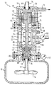
Eine beispielsweise Ausführungsform der Erfindung wird nachfolgend anhand der einzigen Figur der Zeichnung erläutert, die im Schnitt ein Rührwerk mit einer Rührwelle und einem Rührorgan zeigt, welches die erfindungsgemäße Anordnung aufweist.An exemplary embodiment of the invention is explained below with reference to the single figure of the drawing, which shows in section a stirrer with a stirrer shaft and a stirrer, which has the arrangement according to the invention.
Die Figur zeigt schematisch ein Rührwerk 10 mit einer zum Beispiel lotrechten Welle 12, an deren unterem Ende ein Rührorgan 14, z.B. ein Rührpropeller mit mehreren Rührarmen, angebracht ist.The figure schematically shows an
Das untere Ende der Welle 12 mit dem Rührorgan 14 ragt in einen Produktbehälter 16 hinein, in welchem sich das zu behandelnde Produkt befindet. Dieses Produkt kann, wie bereits ausgeführt, ein toxisches, ein radioaktives, ein aggressives oder ein explosives Medium sein oder auch eine Feststoffsuspension, wobei in diesem Fall eine praktisch leckagefreie Abdichtung nach außen verlangt wird.The lower end of the
Die Welle 12 ist radial und axial in Lagern 18, 20, insbesondere Wälzlagern, drehbar gelagert, wobei die Lager 18, 20 ihrerseits in einem Gehäuseteil 22, der sogenannten Lagerlaterne, eingebaut und abgestützt sind.The
Die Lagerlaterne 22 ist mit dem Produktbehälter 16 fest, z.B. durch nicht näher dargestellte Schrauben, verbunden, wobei zwischen diesen beiden Teilen eine ringförmige Dichtung 82 angeordnet ist.The
Auf das obere Ende der Lagerlaterne 22 ist eine Haube 24 aufgesetzt, die mit der ersteren ebenfalls durch Schrauben fest verbunden ist, wobei zwischen der Haube 24 und der Lagerlaterne 22 ebenfalls eine Dichtung, z.B. ein Dichtring 74, eingesetzt ist, wie im einzelnen noch erläutert wird.On the upper end of the
Die Drehmomentübertragung auf die Welle 12 erfolgt über eine Magnetkupplung 26, die aus einem Außenkupplungsteil 30 und einem Innenkupplungsteil 28 besteht, wobei das Außenkupplungsteil 30 an seiner Innenwand und das Innenkupplungsteil 28 an seinem Außenumfang mit Permanentmagneten 32 besetzt ist.The torque is transmitted to the
Das Außenkupplungsteil 30 ist innerhalb der Haube 24 drehbar eingebaut und mit einer Antriebswelle 34 gekoppelt, welche sich durch die Haube 24 nach außen erstreckt und die ihrerseits mit einem nicht dargestellten Antriebsmotor gekoppelt ist für den Antrieb des Außenkupplungsteiles 30. Zwischen der Antriebswelle 34 und der Haube 24 ist ein Dichtring 80 angeordnet.The
Das Innenkupplungsteil 28 ist mit der Rührerwelle 12 fest verbunden oder es ist, wie im dargestellten Beispiel, einteilig mit dieser ausgeführt.The
Zwischen dem Innenkupplungsteil 28 und dem Außenkupplungsteil 30 ist ein statisches Dichtelement 36 eingebaut, das etwa topfförmige Gestalt hat und das an seinem, in der Figur unteren offenen Ende mit einem radial auswärts gerichteten Bund 84 versehen ist, der zwischen der Lagerlaterne 22 und der Haube 24 zusammen mit der Dichtung 74 angeordnet und durch die beiden Teile 22, 24 zusammengespannt ist, womit das Dichtelement 36 eine statische hermetische Abdichtung des Innenraumes des Rührwerkes nach außen zur Atmosphäre bewirkt.A
Das Dichtelement 36, das in der dargestellten Ausführungsform den sogenannten Spalttopf der Magnetkupplung 26 bildet, besteht z.B. aus einem metallfreien Faserverbundwerkstoff und es trennt den Druckbereich des Rührwerkes von der Atmosphäre. Bei Verwendung eines solchen Materials werden unerwünschte Wirbelströme bei der berührungslosen Übertragung des Drehmomentes vom Außenkupplungsteil 30 auf das Innenkupplungsteil 28 vermieden. Das Dichtelement 36 kann aber auch aus einem elektrisch leitenden Werkstoff bestehen, wobei dann zweckmäßigerweise eine Kühlung verwendet wird, wie sie bei der dargestellten und beschriebenen Ausführungsform vorgesehen ist.The
Auf der Seite des Produktbehälters 16 ist zwischen der Rührerwelle 12 und dem Gehäuseteil 22 eine Gleitringdichtung eingebaut, die aus einem stationären Ring 38 und einem mit der Welle 12 umlaufenden Ring 40 gebildet ist.On the side of the
Zwischen dem stationären Ring 38 und dem Gehäuse 22 sitzt eine ringförmige Dichtung 76, ebenso ist zwischen dem mit der Welle 12 umlaufenden Ring 40 und der Welle ein Dichtring 78 angeordnet.An
Die einander zugewandten Stirnflächen der beiden Ringe 38 und 40 gleiten im Betrieb aufeinander unter Bildung eines sehr engen Spaltes und die beiden Ringe der Gleitringdichtung werden durch den Differenzdruck zwischen dem Druck im Produktbehälter 16 und dem Druck im Innenraum 86 des Gehäuses gegeneinandergedrückt.The mutually facing end faces of the two
Der Druck im Innenraum des Produktbehälters 16 wird z.B. durch ein Manometer 62 und der Druck im Innenraum 86 des Gehäuses wird z.B. durch ein Manometer 60 gemessen.The pressure in the interior of the
Die Gleitringe können aus SiC, Si/SiC oder aus Kohle bestehen, die je nach Anwendung miteinander kombiniert werden können. Sie können unter anderem auch bei Feststoffsuspensionen und auch bei Behandlung von klebenden und krustenden Produkten eingesetzt werden.The slide rings can be made of SiC, Si / SiC or carbon, which can be combined with each other depending on the application. Among other things, they can also be used for solid suspensions and also for the treatment of sticky and crusty products.
Die Gleitringdichtung kann ferner auch unterhalb des Niveaus des zu behandelnden Produktes, d.h. eingetaucht in dieses, angeordnet sein.The mechanical seal can also be below the level of the product to be treated, i.e. immersed in this, be arranged.
Der Innenraum 86 des Rührwerkgehäuses zwischen der Gleitringdichtung und dem statischen Dichtelement kann vollständig mit einem Gas, z.B. Stickstoff, gefüllt sein, der über eine Leitung 58 eingefüllt und nachgefüllt werden kann. In diesem Fall sind die Lager 18 und 20 trockenlaufende Lager, z.B. aus keramischen Werkstoffen oder aus Kunststoffen.The interior 86 of the agitator housing between the mechanical seal and the static sealing element can be completely filled with a gas, e.g. Nitrogen can be filled, which can be filled in and refilled via a
In der dargestellten Ausführungsform ist der Innenraum 86 mit einer Schmierflüssigkeit gefüllt, entweder vollständig oder so weit, daß das obere Lager 20 gerade in das Schmiermittel eintaucht. In diesem Fall wird über dem Füllstand der produktneutralen Schmierflüssigkeit ein neutrales Gas, insbesondere Stickstoff, eingefüllt und zwischen dem Schmierflüssigkeitsspiegel und dem topfförmigen Dichtelement 36 ein Gaspolster unter Druck aufrechterhalten, durch welches die Schmierflüssigkeit druckbeaufschlagt wird.In the illustrated embodiment, the interior 86 is filled with a lubricating fluid, either completely or to the extent that the
Der Druck im Gaspolster und damit in der Schmierflüssigkeit wird über die Leitung 58 von einer äußeren Gasversorgung auf etwa 0 bis etwa 3 bar über dem Druck im Produktbehälter 16 gehalten. Dies ist auch dann der Fall, wenn der Innenraum 86 des Gehäuses vollständig mit Gas oder vollständig mit Schmierflüssigkeit gefüllt ist.The pressure in the gas cushion and thus in the lubricating liquid is kept via
Da der Druck im Innenraum 86 somit mindestens gleich dem Druck im Produktbehälter 16, vorzugsweise aber etwas höher ist, kann aus dem Produktbehälter 16 kein Produkt in den Innenraum 86 eindringen.Since the pressure in the interior 86 is thus at least equal to the pressure in the
Die Leckage an Schmierflüssigkeit ist bei einer Druckdifferenz bis zu 3 bar an der Gleitringdichtung sehr gering. Im Bedarfsfalle kann dann Schmierflüssigkeit über eine Leitung 56 nachgefüllt werden.The leakage of lubricant is very low with a pressure difference of up to 3 bar at the mechanical seal. If necessary, lubricant can then be refilled via a
Die Schmierflüssigkeit dient nicht nur zur Schmierung der Gleitringdichtung, sondern auch zur Kühlung und Abfuhr der an der Gleitringdichtung und gegebenenfalls an der Magnetkupplung entstehenden Wärme.The lubricant not only serves to lubricate the mechanical seal, but also to cool and dissipate the heat generated on the mechanical seal and, if applicable, on the magnetic coupling.
Zu diesem Zweck sind auf der Welle Pumpen 42, 48 und 54 angeordnet.For this purpose, pumps 42, 48 and 54 are arranged on the shaft.
Die Pumpe 42 sitzt zwischen der Gleitringdichtung und dem unteren Lager 18, sie läuft mit der Welle 12 um und saugt über axiale Kanäle die Schmierflüssigkeit an und schleudert die letztere infolge der Fliehkraft radikal nach außen. Im Gehäuse 22 sind zwei Überströmkanäle 44 ausgebildet, die den Bereich des Innenraumes 86 unter dem Lager 18 mit dem Bereich oberhalb des Lagers 18 verbinden. (Selbstverständlich kann auch nur ein solcher Überströmkanal 44 oder mehr als zwei Kanäle vorgesehen sein).The
In der Welle 12 ist ebenfalls ein Überströmkanal 46 ausgebildet, der den Bereich des Innenraumes 86 oberhalb des Lagers 18 mit dem Bereich unmittelbar bei der Gleitringdichtung verbindet, wodurch eine Umwälzung der Schmierflüssigkeit von der Gleitringdichtung 38, 40 über die Pumpe 42 und die Überströmkanäle 44 zu dem Bereich des Innenraumes 86 oberhalb des Lagers 18 erfolgt und von dort zurück durch den Überströmkanal 46 zur Gleitringdichtung.An
Das in der Figur obere Ende der Welle bzw. der Innenkupplungsteil 28 ist ebenfalls mit einer Pumpe 48 versehen in Form einer Querbohrung im Innenkupplungsteil 28 oberhalb der Permanentmagnete 32, von welcher Querbohrung eine axiale Bohrung 50 in der Welle 12 abzweigt und nach unten verläuft, bis unterhalb des oberen Lagers 20, wo die axiale Bohrung 50 über eine kurze Querbohrung 52 in den Innenraum 86 des Gehäuses mündet. Ferner ist im Gehäuse, d.h. in der Lagerlaterne 22, ein weiterer überströmkanal 70 ausgebildet, der oberhalb und unterhalb des oberen Lagers 20 in den Innenraum 86 mündet. (Es ist nur ein solcher Überströmkanal 70 dargestellt, es können aber auch mehrere vorgesehen sein).The upper end of the shaft or the
Wenn sich die Welle 12 dreht, wird Schmierflüssigkeit unterhalb des Lagers 20 über die Querbohrung 52 und die Längsbohrung 50 angesaugt, dann durch die die Pumpe bildende Querbohrung 48 infolge der Fliehkraft radial nach außen gefördert, worauf die Schmierflüssigkeit zwischen dem topfförmigen Dichtelement 36 und dem Innenkupplungsteil 28 nach unten fließen und über den Oberströmkanal 70 wieder in den Bereich unterhalb des Lagers 20 gelangen kann, wo sie wieder in die Querbohrung 52 eintreten kann, womit der Kreislauf geschlossen ist.When the
Durch die Pumpe 42 kann somit die Wärme von der Gleitringdichtung 38, 40 und durch die Pumpe 48 kann die Wärme von der Magnetkupplung 26 abgeführt werden.The heat from the
Auf der Welle sitzt ferner drehfest mit ihr verbunden im Bereich zwischen den beiden Lagern 18 und 20 ein Pumpenrad 54, durch das die Schmierflüssigkeit im Innenraum 86 umgewälzt wird, um die Wärme, die sie enthält, an eine Gehäusekühlung 64 abzugeben.On the shaft, there is also connected in a rotationally fixed manner in the area between the two
Das Gehäuse, insbesondere die Lagerlaterne 22, ist mit Kühlkanälen, wie z.B. 64, versehen, denen über eine Zulaufleitung 66 ein Kühlmittel, z.B. Kühlwasser, zugeführt und über eine Ablaufleitung 68 wieder abgeführt wird.The housing, in particular the bearing
Die Schmierflüssigkeit wird, wie bereits ausgeführt, über die Leitung 56 zugeführt bzw. nachgefüllt und ihr Druck und damit der Druck im Innenraum 86 wird durch das Manometer 60 gemessen.As already stated, the lubricating liquid is supplied or refilled via
Im Stillstand des Rührwerkes dichtet die Gleitringdichtung 38, 40 gegen den vollen Druck im Produktbehälter 16 ab.When the agitator is at a standstill, the
Im Betrieb wird eine Leckage vermieden, da der Druck im Innenraum 86 des Rührwerkes höher ist als im Produktbehälter 16, wobei der Differenzdruck an der Gleitringdichtung zweckmäßigerweise bei etwa 0 bis 15 % des Druckes im Produktbehälter 16 liegt.Leakage is avoided during operation since the pressure in the
Sollte die Gleitringdichtung undicht werden, so wird eine nicht gezeigte Nachfüllpumpe für die Schmierflüssigkeit eingeschaltet und/oder gegebenenfalls der Druck des Gaspolsters erhöht und ein Alarm ausgelöst. Erhöht sich die Leckage, so schaltet das Rührwerk automatisch ab.If the mechanical seal should leak, a refill pump (not shown) for the lubricant is switched on and / or if necessary the pressure of the gas cushion is increased and an alarm is triggered. If the leakage increases, the agitator switches off automatically.
Sollte das statische, hermetisch abdichtende Dichtelement 36 undicht werden, so daß der Druck im Innenraum 86 des Gehäuses abfällt, so wird das Rührwerk ebenfalls abgeschaltet. Für den Fall, daß dann noch die Gleitringdichtung undicht werden sollte, kann die Leckage über eine Leitung 72 zur Verbrennung, zur Abgaswäsche oder in einen Sicherheitstank abgeleitet werden.Should the static, hermetically sealing sealing
Nach einer anderen, nicht dargestellten Ausführungsform kann das statische Dichtelement 36 das Gehäuse für einen Antriebsmotor bilden, der gegebenenfalls über ein Getriebe mit dem oberen Ende der Rührerwelle 12 gekoppelt ist. In diesem Fall ist dann der gesamte Antrieb einschließlich des etwa erforderlichen Getriebes innerhalb des statischen, hermetisch abdichtenden Elementes 36 eingebaut.According to another embodiment, not shown, the
Auch kann das untere Lager im Produktbehälter 16 und das obere Lager im Bereich des Antriebselementes angeordnet sein, wobei dann die Gleitringdichtung zwischen den beiden Lagern liegt. Schließlich kann gemäß einer weiteren, nicht dargestellten Ausführungsform die Welle mit ihren Lagern 18, 20, die durch die Gleitringdichtung 38, 40 und das statische Dichtelement 36 abgedichtet sind, vollständig von dem zu behandelnden Produkt umgeben sein.The lower bearing can also be arranged in the
Claims (14)
- Arrangement for sealing the mounting and the drive element (28) of a rotating shaft (12), in particular of stirring mechanisms and/or pump impellers, in closed containers (16), in which corrosive, explosive, radioactive or toxic media or solid suspensions are treated, the shaft (12) being mounted when working in a housing (22, 24), such that its one end projects into the product to be treated, whereas the drive element (28) is arranged on its other end, and a static, hermetically sealing sealing element (36) being arranged on the drive side between the shaft (12) and the drive element (28) on the one hand and the housing (22, 24) on the other hand, a floating ring seal (38, 40) being arranged on the product side between the shaft (12) and the housing (22) to seal the product chamber with respect to a housing inner chamber (86), in which bearings (18, 20) are arranged for the shaft (12) and the drive element (coupling inner part) (28) connected firmly to the shaft (12), the static sealing element (36) hermetically seals the housing inner chamber (86) externally from the atmosphere and the housing inner chamber (86) with the bearings (18, 20) between the floating ring seal (38, 40) and the static sealing element (36) is exposed to a fluid pressure which is at least approximately the same, but preferably above the pressure in the product container (16).
- Arrangement according to claim 1, characterised in that the drive element is the inner part of a magnetic coupling (26) comprising inner coupling Part (28) and outer coupling part (30), and in that the static sealing element (36) is the slot cap of the magnetic coupling (26).
- Arrangement according to claim 1, characterised in that the inner chamber (86) of the housing is filled with a lubricating fluid between the floating ring seal (38, 40) and the static sealing element (36).
- Arrangement according to claim 3, characterised in that the inner chamber (86) of the housing is only partly, in particular to the upper bearing (20), filled with lubricating fluid, and a gas cushion, in particular of nitrogen, is provided above the level of the lubricating fluid, by means of which gas cushion the lubricating fluid is exposed to pressure.
- Arrangement according to claim 1, characterised in that the inner chamber (86) of the housing is filled with a gas, in particular nitrogen, between the floating ring seal (38, 40) and the static sealing element (36).
- Arrangement according to claim 3 or 5, characterised in that the pressure in the lubricating fluid or in the gas is approximately 0 to 3 bar above the pressure in the product container (16).
- Arrangement according to one of the preceding claims, characterised in that a pump (42) is arranged on the shaft (12) between the lower bearing (18) and the floating ring seal (38, 40) to remove the heat being produced at the floating ring seal via the lubricating fluid at a housing cooling mechanism (64).
- Arrangement according to one of the preceding claims, characterised in that the upper end of the shaft (12) is provided with a pump (48) to remove heat from the drive element (28) via the lubricating fluid to a housing cooling mechanism (64).
- Arrangement according to one of claims 3 to 8, characterised in that a pump impeller (54) is arranged on the shaft (12), in particular between the bearings (18, 20) to circulate the lubricant and to remove the heat at a housing cooling mechanism (64).
- Arrangement according to claim 2, characterised in that the outer coupling part (30) of the magnetic coupling (26) is sealingly enclosed by a cap (24) provided with a blow-off line (72).
- Arrangement according to claim 1, characterised in that the static sealing element (36) is the housing for a drive motor which is optionally coupled to the shaft (12) via a set of gears.
- Arrangement according to claim 1, characterised in that the floating ring seal is arranged to be immersed in the product.
- Arrangement according to claim 1, characterised in that the shaft with its bearings and the drive element, which are sealed by the floating ring seal and the static sealing element, is completely surrounded by the product.
- Arrangement according to one of the preceding claims, characterised in that the pressure differential at the floating ring seal (38, 40) is approximately 0 to 15 % of the pressure in the product container (16).
Applications Claiming Priority (2)
| Application Number | Priority Date | Filing Date | Title |
|---|---|---|---|
| DE3818890 | 1988-06-03 | ||
| DE3818890A DE3818890A1 (en) | 1988-06-03 | 1988-06-03 | ARRANGEMENT FOR SECURELY SEALING THE BEARING OF A ROTATING SHAFT WITH AN RELATED DRIVE ELEMENT |
Publications (3)
| Publication Number | Publication Date |
|---|---|
| EP0344532A2 EP0344532A2 (en) | 1989-12-06 |
| EP0344532A3 EP0344532A3 (en) | 1990-09-05 |
| EP0344532B1 true EP0344532B1 (en) | 1994-07-13 |
Family
ID=6355767
Family Applications (1)
| Application Number | Title | Priority Date | Filing Date |
|---|---|---|---|
| EP89108965A Revoked EP0344532B1 (en) | 1988-06-03 | 1989-05-18 | Sealing device of the bearing of a rotating shaft with its drive unit |
Country Status (4)
| Country | Link |
|---|---|
| US (1) | US5108715A (en) |
| EP (1) | EP0344532B1 (en) |
| AT (1) | ATE108525T1 (en) |
| DE (2) | DE3818890A1 (en) |
Families Citing this family (39)
| Publication number | Priority date | Publication date | Assignee | Title |
|---|---|---|---|---|
| FR2672636B1 (en) * | 1991-02-12 | 1995-01-13 | Bertin & Cie | ROTATING MACHINE OF THE COMPRESSOR OR TURBINE TYPE FOR COMPRESSION OR EXPANSION OF A DANGEROUS GAS. |
| DE4135709C1 (en) * | 1991-10-30 | 1993-05-19 | Blohm + Voss Ag, 2000 Hamburg, De | |
| DE4214848C2 (en) * | 1992-05-05 | 1995-09-14 | John Crane Gmbh | Permanent magnetic central coupling with containment shell of separate shafts |
| US5308229A (en) * | 1992-06-03 | 1994-05-03 | Pmc Liquiflo Equipment Company | Pump having an internal gas pump |
| US5368390A (en) * | 1993-03-01 | 1994-11-29 | General Signal Corporation | Mixer systems |
| DE4310266A1 (en) * | 1993-03-30 | 1994-10-06 | Draiswerke Gmbh | mixer |
| DE9310578U1 (en) * | 1993-07-15 | 1994-11-17 | Feodor Burgmann Dichtungswerke GmbH & Co, 82515 Wolfratshausen | Sterilizable drive device |
| US5879081A (en) * | 1995-01-09 | 1999-03-09 | Chordia; Lalit M. | Mixing apparatus having self-sealing spring-loaded seals |
| US5553867A (en) * | 1995-04-21 | 1996-09-10 | Environamics Corporation | Triple cartridge seal having one inboard and two concentric seals for chemical processing pump |
| JPH0989120A (en) * | 1995-09-22 | 1997-03-31 | Pioneer Electron Corp | Vacuum device |
| US20040009610A1 (en) * | 1999-04-29 | 2004-01-15 | The University Of Wyoming Research Corporation D/B/A Western Research Institute | Organic contaminant soil extraction system |
| DE29923340U1 (en) * | 1999-08-26 | 2001-04-26 | Becker, Peter, Dipl.-Ing., 59423 Unna | Non-contact gas and pressure-tight drive system |
| ATE234669T1 (en) * | 1999-11-10 | 2003-04-15 | Buss Sms Gmbh Verfahrenstechni | MIXER AND REACTOR |
| US6572261B1 (en) | 2001-06-12 | 2003-06-03 | Walker Stainless Equipment Company | Horizontal agitator |
| DE10241026B4 (en) * | 2002-09-05 | 2004-09-30 | EISENMANN Maschinenbau KG (Komplementär: Eisenmann-Stiftung) | Transport trolley for a system for treating, in particular for painting, objects, in particular vehicle bodies |
| US7670118B2 (en) * | 2003-02-03 | 2010-03-02 | Cap Co., Ltd. | Hot gas blowing fan |
| US6997601B2 (en) * | 2003-07-08 | 2006-02-14 | Feldmeier Equipment, Inc. | Agitator with removable blades for sanitary tank |
| TWI266468B (en) * | 2005-10-31 | 2006-11-11 | Sunonwealth Electr Mach Ind Co | Power indirectly linked towing apparatus |
| RU2310636C1 (en) * | 2006-03-02 | 2007-11-20 | Федеральное государственное унитарное предприятие "Научно-исследовательский институт полимерных материалов" | End face seal of explosive composition mixer shaft and method for impregnation of felt seal ring for end face seal of explosive composition mixer shaft |
| EP2214847B1 (en) | 2007-11-08 | 2018-08-08 | P&T Global Solutions, LLC | System for and method of filling a container with hazardous waste |
| EP2180583B1 (en) | 2008-10-24 | 2012-08-08 | Biazzi Sa | Device with mixing vessel |
| NL2002417C2 (en) * | 2009-01-15 | 2010-07-19 | Avantium Holding B V | Stir system. |
| CN101800464B (en) * | 2010-01-28 | 2011-11-09 | 清华大学 | Sealing and driving device in high-temperature gas-cooled reactor helium gas space and driving device thereof |
| SE534766C2 (en) * | 2010-04-26 | 2011-12-13 | Itt Mfg Enterprises Inc | Implementation for digestion |
| WO2014098746A1 (en) * | 2012-12-21 | 2014-06-26 | Cassandra Oil Technology Ab | Gastight reactor comprising rotating crushing means |
| DE102013007849A1 (en) * | 2013-05-08 | 2014-11-13 | Ksb Aktiengesellschaft | pump assembly |
| US9945485B2 (en) * | 2015-05-04 | 2018-04-17 | Trelleborg Sealing Solutions Us, Inc. | Seal assembly for a sterile environment |
| DE102015005736A1 (en) * | 2015-05-07 | 2016-11-10 | Ika-Werke Gmbh & Co. Kg | Magnetic coupling and stirring device with magnetic coupling |
| DE202016100655U1 (en) * | 2016-02-10 | 2017-05-11 | Speck Pumpen Vakuumtechnik Gmbh | Magnetic drive pump |
| CN107120253A (en) * | 2016-02-25 | 2017-09-01 | 衡阳瑞达电源有限公司 | A kind of electric pump |
| JP2019196721A (en) * | 2018-05-08 | 2019-11-14 | アイシン精機株式会社 | Water pump |
| CN111701523B (en) * | 2020-06-28 | 2022-06-14 | 中国兵器装备集团自动化研究所 | Kneading safety transmission device |
| CN112599275B (en) * | 2021-02-02 | 2021-06-01 | 杭州景业智能科技股份有限公司 | Sealing station port of bar scrap decontamination packaging system for nuclear industry |
| CN113757130B (en) * | 2021-09-02 | 2024-04-02 | 安徽凯特泵业有限公司 | Self-adjusting chemical pump |
| CN114179409B (en) * | 2021-12-13 | 2023-09-29 | 山东豪迈机械科技股份有限公司 | A tire vulcanization equipment |
| CN114179410B (en) | 2021-12-13 | 2023-09-29 | 山东豪迈机械科技股份有限公司 | A vulcanization equipment |
| US12203475B2 (en) * | 2022-08-23 | 2025-01-21 | Saudi Arabian Oil Company | Magnetic drive sealless pumps with steam jacket |
| CN116036950B (en) * | 2023-02-02 | 2024-03-22 | 南通京源化工机械有限公司 | Magnetic drive stirrer with long service life |
| DE102024002255A1 (en) | 2024-07-10 | 2026-01-15 | Idoneus Anlagenbau Gmbh | Drive unit for a height-adjustable agitator in a process vessel |
Family Cites Families (13)
| Publication number | Priority date | Publication date | Assignee | Title |
|---|---|---|---|---|
| US2698773A (en) * | 1951-03-17 | 1955-01-04 | Ohio Crankshaft Co | Lubricant cooling system |
| GB922319A (en) * | 1960-03-28 | 1963-03-27 | Klaus Franz | Centrifugal pump |
| US3106099A (en) * | 1960-11-09 | 1963-10-08 | Exxon Research Engineering Co | Fluid seal for a reciprocating shaft |
| US3749411A (en) * | 1971-07-19 | 1973-07-31 | Nettco Corp | Shaft sealing system |
| US4029323A (en) * | 1972-04-11 | 1977-06-14 | Nippon Seiko Kabushiki Kaisha | Fluid pressure seal arrangement |
| US4135253A (en) * | 1976-11-30 | 1979-01-23 | Medtronic, Inc. | Centrifugal blood pump for cardiac assist |
| US4407513A (en) * | 1977-04-12 | 1983-10-04 | Taiho Kogyo Co., Ltd. | Mechanical seal |
| US4234447A (en) * | 1978-07-17 | 1980-11-18 | The Dow Chemical Company | Mixing method and container therefor |
| FR2472817A1 (en) * | 1979-12-28 | 1981-07-03 | Kobe Steel Ltd | RADIOACTIVE WASTE TREATMENT FACILITY |
| US4582638A (en) * | 1981-03-27 | 1986-04-15 | General Signal Corporation | Method and means for disposal of radioactive waste |
| DE3341960A1 (en) * | 1983-11-21 | 1985-05-30 | EKATO Industrieanlagen Verwaltungsgesellschaft mbH u. Co, 7860 Schopfheim | AGITATOR |
| US4666676A (en) * | 1985-08-30 | 1987-05-19 | The United States Of America As Represented By The United States Department Of Energy | Radioactive waste processing apparatus |
| US4844707A (en) * | 1987-06-12 | 1989-07-04 | Kletschka Harold D | Rotary pump |
-
1988
- 1988-06-03 DE DE3818890A patent/DE3818890A1/en not_active Withdrawn
-
1989
- 1989-05-18 EP EP89108965A patent/EP0344532B1/en not_active Revoked
- 1989-05-18 DE DE58908033T patent/DE58908033D1/en not_active Revoked
- 1989-05-18 AT AT89108965T patent/ATE108525T1/en not_active IP Right Cessation
- 1989-05-31 US US07/359,113 patent/US5108715A/en not_active Expired - Fee Related
Also Published As
| Publication number | Publication date |
|---|---|
| DE58908033D1 (en) | 1994-08-18 |
| ATE108525T1 (en) | 1994-07-15 |
| DE3818890A1 (en) | 1989-12-07 |
| EP0344532A2 (en) | 1989-12-06 |
| US5108715A (en) | 1992-04-28 |
| EP0344532A3 (en) | 1990-09-05 |
Similar Documents
| Publication | Publication Date | Title |
|---|---|---|
| EP0344532B1 (en) | Sealing device of the bearing of a rotating shaft with its drive unit | |
| DE69427944T2 (en) | MIXER ARRANGEMENTS | |
| DE1294936B (en) | Stirring device | |
| DE68921755T2 (en) | DYNAMIC SEALING ARRANGEMENT FOR A SCREW PUMP. | |
| DE112006000814B4 (en) | Ultra-pure magnetic mixer | |
| DE2016493A1 (en) | Pump unit | |
| DE1811100A1 (en) | Device for lubricating a bearing for use in an enclosed motor pump or an enclosed motor agitator | |
| DE69611316T2 (en) | Liquid pump | |
| DE69705306T2 (en) | HYDRAULIC MACHINE | |
| EP0617999B1 (en) | Mixer with magnetic coupling | |
| DE69914389T2 (en) | Sealing device for pumps | |
| DE1653664A1 (en) | Self-priming centrifugal pump | |
| DE3637501C2 (en) | Axial thrust compensation for centrifugal pumps | |
| DE2160861B2 (en) | Lubrication and filter device for electrically-driven circulation pump - uses part of circulating fluid for motor cooling and for shaft bearing lubrication | |
| EP0126239B1 (en) | Contactless seal | |
| WO2013189571A1 (en) | Motorized centrifugal pump with a rotary seal | |
| DE69008598T2 (en) | Mechanical seal. | |
| DE2460748B2 (en) | CIRCULATION PUMP FOR HEATING AND HOT WATER SYSTEMS IN PARTICULAR | |
| DE202016100655U1 (en) | Magnetic drive pump | |
| EP0233593B1 (en) | Bearing for engine shafts | |
| EP1211422B1 (en) | Rotor of a canned motor for a canned motor pump | |
| EP0359136A1 (en) | Sealless centrifugal pump suited for cleaning | |
| DE9207883U1 (en) | Cleanable glandless centrifugal pump | |
| EP0487882A1 (en) | Mechanical seal | |
| DE69527795T2 (en) | DEVICE WITH COMBINED SEAL / BEARING ARRANGEMENT |
Legal Events
| Date | Code | Title | Description |
|---|---|---|---|
| PUAI | Public reference made under article 153(3) epc to a published international application that has entered the european phase |
Free format text: ORIGINAL CODE: 0009012 |
|
| AK | Designated contracting states |
Kind code of ref document: A2 Designated state(s): AT CH DE ES FR GB IT LI NL SE |
|
| PUAL | Search report despatched |
Free format text: ORIGINAL CODE: 0009013 |
|
| AK | Designated contracting states |
Kind code of ref document: A3 Designated state(s): AT CH DE ES FR GB IT LI NL SE |
|
| 17P | Request for examination filed |
Effective date: 19901207 |
|
| 17Q | First examination report despatched |
Effective date: 19920717 |
|
| GRAA | (expected) grant |
Free format text: ORIGINAL CODE: 0009210 |
|
| AK | Designated contracting states |
Kind code of ref document: B1 Designated state(s): AT CH DE ES FR GB IT LI NL SE |
|
| PG25 | Lapsed in a contracting state [announced via postgrant information from national office to epo] |
Ref country code: GB Effective date: 19940713 Ref country code: IT Free format text: LAPSE BECAUSE OF FAILURE TO SUBMIT A TRANSLATION OF THE DESCRIPTION OR TO PAY THE FEE WITHIN THE PRE;WARNING: LAPSES OF ITALIAN PATENTS WITH EFFECTIVE DATE BEFORE 2007 MAY HAVE OCCURRED AT ANY TIME BEFORE 2007. THE CORRECT EFFECTIVE DATE MAY BE DIFFERENT FROM THE ONE RECORDED.SCRIBED TIME-LIMIT Effective date: 19940713 |
|
| REF | Corresponds to: |
Ref document number: 108525 Country of ref document: AT Date of ref document: 19940715 Kind code of ref document: T |
|
| ET | Fr: translation filed | ||
| REF | Corresponds to: |
Ref document number: 58908033 Country of ref document: DE Date of ref document: 19940818 |
|
| PG25 | Lapsed in a contracting state [announced via postgrant information from national office to epo] |
Ref country code: SE Effective date: 19941013 |
|
| PG25 | Lapsed in a contracting state [announced via postgrant information from national office to epo] |
Ref country code: ES Free format text: LAPSE BECAUSE OF FAILURE TO SUBMIT A TRANSLATION OF THE DESCRIPTION OR TO PAY THE FEE WITHIN THE PRESCRIBED TIME-LIMIT Effective date: 19941014 |
|
| GBV | Gb: ep patent (uk) treated as always having been void in accordance with gb section 77(7)/1977 [no translation filed] |
Effective date: 19941013 |
|
| GBV | Gb: ep patent (uk) treated as always having been void in accordance with gb section 77(7)/1977 [no translation filed] |
Effective date: 19940713 |
|
| GBV | Gb: ep patent (uk) treated as always having been void in accordance with gb section 77(7)/1977 [no translation filed] |
Free format text: DATE CORRECTED TO 940713 |
|
| PLBI | Opposition filed |
Free format text: ORIGINAL CODE: 0009260 |
|
| 26 | Opposition filed |
Opponent name: FEODOR BURGMANN DICHTUNGSWERKE GMBH & CO. Effective date: 19950411 Opponent name: JOHN CRANE UK LIMITED Effective date: 19950411 |
|
| NLR1 | Nl: opposition has been filed with the epo |
Opponent name: JOHN CRANE UK LIMITED Opponent name: FEODOR BURGMANN DICHTUNGSWERKE GMBH & CO. |
|
| PGFP | Annual fee paid to national office [announced via postgrant information from national office to epo] |
Ref country code: DE Payment date: 19970523 Year of fee payment: 9 |
|
| PGFP | Annual fee paid to national office [announced via postgrant information from national office to epo] |
Ref country code: FR Payment date: 19970616 Year of fee payment: 9 |
|
| PGFP | Annual fee paid to national office [announced via postgrant information from national office to epo] |
Ref country code: AT Payment date: 19970619 Year of fee payment: 9 |
|
| PGFP | Annual fee paid to national office [announced via postgrant information from national office to epo] |
Ref country code: CH Payment date: 19970623 Year of fee payment: 9 |
|
| PGFP | Annual fee paid to national office [announced via postgrant information from national office to epo] |
Ref country code: NL Payment date: 19970630 Year of fee payment: 9 |
|
| RDAH | Patent revoked |
Free format text: ORIGINAL CODE: EPIDOS REVO |
|
| RDAG | Patent revoked |
Free format text: ORIGINAL CODE: 0009271 |
|
| STAA | Information on the status of an ep patent application or granted ep patent |
Free format text: STATUS: PATENT REVOKED |
|
| 27W | Patent revoked |
Effective date: 19971218 |
|
| REG | Reference to a national code |
Ref country code: CH Ref legal event code: PL |
|
| NLR2 | Nl: decision of opposition |