EP0344077B1 - Präzisionsbearbeitungsmaschine mit einer Stange zum Bestimmen der Mittelwertachse eines zylindrischen Loches - Google Patents
Präzisionsbearbeitungsmaschine mit einer Stange zum Bestimmen der Mittelwertachse eines zylindrischen Loches Download PDFInfo
- Publication number
- EP0344077B1 EP0344077B1 EP89420182A EP89420182A EP0344077B1 EP 0344077 B1 EP0344077 B1 EP 0344077B1 EP 89420182 A EP89420182 A EP 89420182A EP 89420182 A EP89420182 A EP 89420182A EP 0344077 B1 EP0344077 B1 EP 0344077B1
- Authority
- EP
- European Patent Office
- Prior art keywords
- rod
- axis
- resilient
- pilot
- along
- Prior art date
- Legal status (The legal status is an assumption and is not a legal conclusion. Google has not performed a legal analysis and makes no representation as to the accuracy of the status listed.)
- Expired - Lifetime
Links
- 238000003754 machining Methods 0.000 claims abstract 9
- 230000001747 exhibiting effect Effects 0.000 claims 4
- 230000006835 compression Effects 0.000 claims 2
- 238000007906 compression Methods 0.000 claims 2
- 230000002093 peripheral effect Effects 0.000 claims 2
- 238000006073 displacement reaction Methods 0.000 claims 1
Images


Classifications
-
- B—PERFORMING OPERATIONS; TRANSPORTING
- B23—MACHINE TOOLS; METAL-WORKING NOT OTHERWISE PROVIDED FOR
- B23C—MILLING
- B23C3/00—Milling particular work; Special milling operations; Machines therefor
- B23C3/02—Milling surfaces of revolution
- B23C3/05—Finishing valves or valve seats
- B23C3/051—Reconditioning of valve seats
- B23C3/053—Reconditioning of valve seats having means for guiding the tool carrying spindle
- B23C3/055—Reconditioning of valve seats having means for guiding the tool carrying spindle for engines
-
- Y—GENERAL TAGGING OF NEW TECHNOLOGICAL DEVELOPMENTS; GENERAL TAGGING OF CROSS-SECTIONAL TECHNOLOGIES SPANNING OVER SEVERAL SECTIONS OF THE IPC; TECHNICAL SUBJECTS COVERED BY FORMER USPC CROSS-REFERENCE ART COLLECTIONS [XRACs] AND DIGESTS
- Y10—TECHNICAL SUBJECTS COVERED BY FORMER USPC
- Y10T—TECHNICAL SUBJECTS COVERED BY FORMER US CLASSIFICATION
- Y10T82/00—Turning
- Y10T82/29—Attachment for cutting a valve
Definitions
- the present invention relates principally according to the preamble of claim 1 a rod for determining the practical mean axis of a hole having a general cylindrical profile, but local imperfections of concentricity of the order of the usual tolerances of machining, for example of the order of a few microns, or less.
- a rod can be part of a machine as defined above, in a fixed or removable manner, in particular as a pilot rod.
- Such a rod can also be used for the physical determination or materialization of the practical mean axis of a cylindrical hole, the axis thus materialized being able to be used for different purposes, such as metrology, rotation of a cutting tool.
- This same rod can serve as a measurement intermediary, and be part of a machining system or equipment, comprising a tool positioned relative to the workpiece, by measuring the position of the rod.
- the invention also relates, according to the preamble to claim 5, on a secondary basis, and independently, to a precision machining machine, with rod for determining the practical mean axis of a hole of generally cylindrical profile.
- machine is meant any heavy equipment of the industrial type, such as machine tool, but also any light equipment of the manual type, such as tools.
- precision machining any work of a metal part with a cutting tool, whether it is a boring, milling, tapping, grinding, or any other form of metal working, by removing a chip, or in the case of an abrasion tool, by removing metal particles.
- the pilot rod chosen and adapted to the dimensional characteristics of the valve guide, turns inside the latter, and the cutting tool works concentric to this same guide.
- the determination of the practical mean axis of the valve guide remains limited by the local defects or imperfections in the concentricity of the reference cylindrical hole that this same guide constitutes.
- Such defects of the order of usual tolerances machining, for example a few microns or less, result as well from the limits or imperfections of the original machining, as from wear differentiated along the axis of the valve guide.
- the determination of the practical mean axis of the valve guide still has limits, even if these are of the order of a few microns.
- the object of the present invention is therefore to improve the determination of the practical mean axis of a reference hole, of generally cylindrical appearance, by taking account of local imperfections along the axis of the hole, however small they may be, and this while retaining the very principle of a pilot rod closely adapted to the average section of the same hole.
- a coaxial elastic bearing of axial extension and continuous circular extension around the rod there is attached to the rigid cylindrical surface of the pilot rod a coaxial elastic bearing of axial extension and continuous circular extension around the rod.
- the stress-free external surface of the elastic bearing that is to say when the pilot rod is not introduced into the reference hole, emerges at least locally above the cylindrical surface of the pilot rod.
- This elastic bearing is capable of establishing under stress, by radial and local elastic compression, a plurality, or even an infinity, of annular zones of continuous peripheral contact, between the local surface of the reference hole and the elastic bearing. And these annular contact zones, compensating for local imperfections in the reference hole, are also staggered along the axis of the pilot rod.
- the coaxial elastic bearing comprises a plurality of elastic rings, staggered along the axis of the pilot rod, elastically deformable in the radial direction, and from which the stress-free external surface emerges at- above the apparent cylindrical surface of the stem.
- the radial elastic compression of these rings, under stress, make it possible to establish a series of annular contacts between the local surface of the reference hole and the pilot rod, staggered along the axis of the latter.
- each of the annular contact zones of the bearing elastic, with the local surface of the reference hole transmits a stress to the rigid rod, whose value depends on that of the local imperfection, hollow, protruding, or nonexistent. All these constraints, staggered along the axis of the rigid rod (for example made of tungsten carbide), balance each other to determine an average position of the rod, which can be used as the practical mean axis of the reference hole.
- the pilot rod according to the invention makes it possible to average the imperfections of the reference hole.
- the elastic bearing of the pilot rod, in contact with the reference hole, makes it possible to stiffen the coaxiality of the pilot rod with the proven practical mean axis, both statically, at the time of centering in the reference hole, and dynamically, when the cutting tool is rotating.
- the rotating assembly formed by the spindle and the coaxial pilot rod is supported in rotation, on either side of the cutting tool, by two real bearings, the first constituted by the sheath present in the machining head, and the second by the elastic bearing of the rod, in local contact with the reference hole.
- the deformable and elastic nature of the elastic seat makes it possible to dampen the vibrations of which the spindle and the pilot rod can be the seat.
- a grinding machine according to the invention incorporates the various technical characteristics already described in patent EP-B-0022796. We will usefully refer to the text of this patent, for construction details.
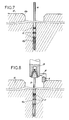
- the pilot rod (11) comprises a plurality of annular housings (11a), hollow relative to the cylindrical surface of the rod (11), and staggered along the axis and the height of the latter.
- Several elastic rings (13), elastically deformable in the radial direction, are mounted in the annular housings (11a) thus defined. Therefore, the shape and transverse dimensions of each ring (13) take account of and are adapted to that of each housing (11a).
- each ring (13a) As shown in Figure 3, the outer surface (13a) of each ring (13a), unconstrained, emerges above the cylindrical surface of the rod (11). And as shown in the lower part of FIG. 1, the elastic radial compression under stress of each ring (13) makes it possible to establish a peripheral contact between the surface of the reference hole (12a), in this case the valve guide. , and the surface of the rod (11).
- each ring has two wings (13b) forming between them an obtuse angle directed from the inside towards the outside of the annular housing (11a). These two wings (13b) are separated by a concave central part (13c), seen from the outside of the ring.
- the rings (13) are produced by molding or extruding any plastic material, composite or not, having both a low coefficient of friction and good resistance to wear in rotation; it may for example be polytetrafluoroetylene.
- the rings (13) can be produced according to any embodiment different from those described with reference to Figures 2 and 3; the rings can be solid, and not hollow, and have a transverse and radial section of different shape or profile.
- the reference hole (12a) actually has a general cylindrical profile, but comprises, in a staggered fashion along its axis, various local concentricity defects.
- the elastic bearing (20) is an elastic sleeve (25) continuous along the axis of the pilot rod (11), the external surface (25a) of which emerges above the residual cylindrical surface of the rod (11).
- the elastic bearing (20) comprises an annular base (26), continuous along the axis of the pilot rod (11), from which the various elastic rings (13) project in a single piece.
- the rod (11) according to the invention described above can be used as such to determine the practical mean axis of the reference hole (12a).
- This physical determination or materialization can be used for different purposes, for example metrology or measurement, the values thus obtained can be used for positioning a tool for example.
- the reference hole (12a) becomes available for machining, for example with a surfacing tool (54), carried out exactly along the practical axis of the guide (12a ) valve.
- the rod (11) remains motionless in rotation, and a head (30) is attached to the free end of the rod (11), while being movable in rotation relative to the latter; motor means not shown, whether manual means or an electric motor, drive the machining head (30) relative to the rod (11).
Landscapes
- Engineering & Computer Science (AREA)
- Mechanical Engineering (AREA)
- Grinding And Polishing Of Tertiary Curved Surfaces And Surfaces With Complex Shapes (AREA)
- Electrical Discharge Machining, Electrochemical Machining, And Combined Machining (AREA)
- Machine Tool Sensing Apparatuses (AREA)
- Rolling Contact Bearings (AREA)
- Grinding Of Cylindrical And Plane Surfaces (AREA)
- Turning (AREA)
- Drilling Tools (AREA)
- Cutting Tools, Boring Holders, And Turrets (AREA)
- Lift Valve (AREA)
Claims (11)
- Stange zur Bestimmung der tatsächlichen Mittelachse einer Bohrung (12a), zum Beispiel einer Ventilführung, deren Sitz (12b) man schleifen will, wobei diese Bohrung ein im wesentlichen zylindrisches Profil mit längs ihrer Achse gestaffelten lokalen Fehlern, beispielsweise in der Konzentrizität, im Bereich üblicher Bearbeitungstoleranzen aufweist und wobei die Stange eine längs ihrer Länge feste zylindrische Oberfläche aufweist, dadurch gekennzeichnet, daß auf der festen zylindrischen Oberfläche der Führungsstange ein koaxiales, elastisches Lager (20) mit axialer Ausdehnung und durchgehender runder Ausdehnung um die Stange herum angebracht ist, dessen Außenfläche ohne Druck wenigstens lokal über die zylindrische Oberfläche der Führungsstange hervorragt, wobei dieses Lager dazu geeignet ist, unter Druckbelastung durch lokale und radiale elastische Komprimierung eine Vielzahl von ringförmigen Zonen mit durchgehendem äußeren Kontakt zwischen der lokalen Oberfläche der Bohrung und dem elastischen Lager aufzubauen und die lokalen Fehler der Bohrung zu kompensieren, wobei die ringförmigen Kontaktzonen gleichfalls längs der Achse der Führungsstange gestaffelt sind.
- Stange nach Anspruch 1, dadurch gekennzeichnet, daß das koaxiale elastische Lager (20) eine längs der Achse der Führungsstange durchgehende elastische Muffe ist, deren zylindrische Außenfläche ohne Druckbelastung über die zu der Stange gehörende zylindrische Oberfläche hervorragt.
- Stange nach Anspruch 1, dadurch gekennzeichnet, daß das koaxiale elastische Lager (20) eine Vielzahl von längs der Achse (8) der Führungsstange gestaffelten, in radialer Richtung elastisch verformbaren elastischen Ringen (13) umfaßt, deren Außenfläche (13a) ohen Druckbelastung über die zu der Stange (11) gehörende zylindrische Oberfläche hervorragt.
- Machine zur Präzisionsbearbeitung, beispielsweise zum Schleifen von Ventilsitzen (12b) von Verbrennungsmotoren, enthaltend einen Bearbeitungskopf (2) mit einer drehfest mit einem Bearbeitungswerkzeug (54) verbundenen Welle (7), wobei eine lösbare Stange nach einem der Ansprüche 1 bis 3 zugeordnet ist, dadurch gekennzeichnet, daß sie Mittel (50, 51, 52) zum Messen der Position der in die Referenzbohrung (12a) eingeführten Stange (11) und Steuermittel (53) für die Verschiebung des Bearbeitungskopfes (2) und/oder der Welle (7) umfaßt, um die letztere entsprechend der gemessenen Position der Stange zu positionieren, während die letztere aus der Referenzbohrung (12a) herausgezogen ist.
- Machine zur Präzisionsbearbeitung, beispielsweise zum Schleifen von Ventilsitzen (12b) von Verbrennungsmotoren, enthaltend eine um seine Achse (8) drehbare und längs seiner Achse (8) in Translationsrichtung bewegbare Welle (7), welche drehfest mit einem Bearbeitungswerkzeug (9) verbunden und an ihrem freien Ende durch eine zu der Achse der Welle koaxiale Führungsstange (11) verlängert ist, die längs ihrer Länge eine feste zylindrische Oberfläche aufweist, und dazu vorgesehen ist, in eine Referenzbohrung (12a), beispielsweise die Ventilführung, deren Sitz (12b) man schliefen will, eingeführt zu werden, wobei diese Bohrung ein im wesentlichen zylindrisches Profil mit längs ihrer Achse gestaffelten lokalen Fehlern, beispielsweise in der Konzentrizität, im Bereich üblicher Bearbeitungstoleranzen aufweist, dadurch gekennzeichnet, daß auf der festen zylindrischen Oberfläche der Führungsstange ein koaxiales, elastisches Lager (20) mit axialer Ausdehnung und durchgehender runder Ausdehnung um die Stange herum angebracht ist, dessen Außenfläche ohen Druckbelastung wenigstens lokal über die zylindrische Oberfläche der Führungsstange hervorragt, wobei dieses Lager dazu geeignet ist, unter Druck durch lokale und radiale elastische Komprimierung eine Vielzahl von ringförmigen Zonen mit durchgehendem äußeren Kontakt zwischen der lokalen Oberfläche der Referenzbohrung und dem elastischen Lager aufzubauen und die lokalen Fehler der Bohrung zu kompensieren, wobei die ringförmigen Kontaktzonen gleichfalls längs der Achse der Führungsstange gestaffelt sind.
- Maschine nach Anspruch 5, dadurch gekennzeichnet, daß das koaxiale elastische Lager (20) eine längs der Achse der Führungsstange durchgehende elastische Muffe ist, deren zylindrische Außenfläche ohen Druckbelastung über die zu der Stange gehörende zylindrische Oberfläche hervorragt.
- Maschine nach Anspruch 5, dadurch gekennzeichnet, daß das koaxiale elastische Lager (20) eine Vielzahl von längs der Achse (8) der Führungsstange gestaffelten, in radialer Richtung elastisch verformbaren elastischen Ringen (13) umfaßt, deren Außenfläche (13a) ohne Druckbeastung über die zu der Stange (11) gehörende zylindrische Oberfläche hervorragt.
- Maschine nach Anspruch 7, dadurch gekennzeichnet, daß die Führungsstange (11) eine Vielzahl von ringförmigen Aufnahmen (11a) umfaßt, die längs der Achse (8) der Führungsstange gestaffelt sowie gegenüber der zylindrischen Oberfläche der letzteren hohl sind, und die die Vielzahl an elastischen Ringen (13) aufnehmen.
- Maschine nach Anspruch 7, dadurch gekennzeichnet, daß das koaxiale elastische Lager (20) ein längs der Achse (8) der Führungsstange (11) durchgehendes ringförmiges Unterteil trägt, von dem die elastischen Ringe (13) einstückig hervorstehen.
- Maschine nach Anspruch 7, dadurch gekennzeichnet, daß im Querschnitt ein elastischer Ring (13) zwei zwischen sich einen stumpfen Winkel ausbildende Schenkel (13b) umfaßt.
- Maschine nach Anspruch 10, dadurch gekennzeichnet, daß im Querschnitt die beiden Schenkel (13b) des Ringes durch einen konkaven Mittenabschnitt (13c) voneinander getrennt sind.
Priority Applications (1)
| Application Number | Priority Date | Filing Date | Title |
|---|---|---|---|
| AT89420182T ATE84250T1 (de) | 1988-05-27 | 1989-05-26 | Praezisionsbearbeitungsmaschine mit einer stange zum bestimmen der mittelwertachse eines zylindrischen loches. |
Applications Claiming Priority (2)
| Application Number | Priority Date | Filing Date | Title |
|---|---|---|---|
| FR8807315A FR2631871B1 (fr) | 1988-05-27 | 1988-05-27 | Machine d'usinage de precision, avec tige pilote |
| FR8807315 | 1988-05-27 |
Publications (2)
| Publication Number | Publication Date |
|---|---|
| EP0344077A1 EP0344077A1 (de) | 1989-11-29 |
| EP0344077B1 true EP0344077B1 (de) | 1993-01-07 |
Family
ID=9366841
Family Applications (1)
| Application Number | Title | Priority Date | Filing Date |
|---|---|---|---|
| EP89420182A Expired - Lifetime EP0344077B1 (de) | 1988-05-27 | 1989-05-26 | Präzisionsbearbeitungsmaschine mit einer Stange zum Bestimmen der Mittelwertachse eines zylindrischen Loches |
Country Status (8)
| Country | Link |
|---|---|
| US (1) | US5001871A (de) |
| EP (1) | EP0344077B1 (de) |
| JP (1) | JPH0224007A (de) |
| AT (1) | ATE84250T1 (de) |
| AU (1) | AU3513389A (de) |
| DE (1) | DE68904245T2 (de) |
| ES (1) | ES2036364T3 (de) |
| FR (1) | FR2631871B1 (de) |
Families Citing this family (12)
| Publication number | Priority date | Publication date | Assignee | Title |
|---|---|---|---|---|
| FR2647043A1 (fr) * | 1989-05-22 | 1990-11-23 | Etude Realisa Diffusion Indle | Outillage pour usinage de precision, par exemple pour la rectification de sieges de soupape |
| FR2648738A2 (fr) * | 1989-05-22 | 1990-12-28 | Etude Realisa Diffusion Indle | Outillage pour usinage de precision, par exemple pour la rectification de sieges de soupape |
| CH682643A5 (de) * | 1990-09-28 | 1993-10-29 | Serdi | Verfahren und Vorrichtung zum Zentrieren eines Führungsdorns in einer Ventilführung zum Zwecke des Präzisionsbearbeitens eines Ventilsitzes. |
| AU7488994A (en) * | 1994-09-02 | 1996-03-27 | Minelli Ag | Device for machining valve seats in internal combustion engines |
| US5613809A (en) * | 1995-06-14 | 1997-03-25 | Harmand; Brice | Apparatus and method for machining valve seats in an engine cylinder head |
| US6086293A (en) * | 1998-04-13 | 2000-07-11 | Harmand Family Limited Partnership | Cutting tool for machining valve seats |
| US6530727B2 (en) | 1998-04-13 | 2003-03-11 | Harmand Family Limited Partnership | Contour machining head |
| US6640410B2 (en) | 1998-04-13 | 2003-11-04 | Harmand Family Limited Partnership | Line transfer system with a contour machining head |
| JP4851666B2 (ja) * | 2001-08-30 | 2012-01-11 | ユニタック株式会社 | ボーリングヘッド |
| ATE485911T1 (de) * | 2005-12-06 | 2010-11-15 | Magnaghi Aeronautica S P A | Verfahren und vorrichtung zum tieflochbohren und zur herstellung von nichtzylindrischen innenkonturen |
| US9108250B1 (en) * | 2012-10-31 | 2015-08-18 | The Boeing Company | Adjustable bushing assemblies |
| CN112077647B (zh) * | 2020-07-28 | 2021-08-03 | 成都飞机工业(集团)有限责任公司 | 一种筒状薄壁开孔器的防振稳定器 |
Family Cites Families (11)
| Publication number | Priority date | Publication date | Assignee | Title |
|---|---|---|---|---|
| US2085280A (en) * | 1934-11-01 | 1937-06-29 | Merle D Tyler | Valve seat grinder |
| US2084175A (en) * | 1934-12-15 | 1937-06-15 | Automotive Maintenance Mach Co | Pilot for valve grinding tools |
| US2200758A (en) * | 1936-01-25 | 1940-05-14 | Guiberson Corp | Rod guide |
| DE903762C (de) * | 1949-10-29 | 1954-02-11 | Franz Burghauser Dipl Ing | Gleit- und Waelzlager fuer stark beanspruchte Drehzapfen |
| FR1070485A (fr) * | 1951-10-05 | 1954-07-27 | Caro Werk Ges M B H | Perfectionnements apportés aux paliers lisses auto-portants |
| FR1080137A (fr) * | 1953-05-26 | 1954-12-07 | Procédé et appareil pour le conditionnement des puits en vue de leur cimentage | |
| FR1108959A (fr) * | 1953-10-06 | 1956-01-19 | Gomma Antivibranti Applic | Guide élastique pour organes en mouvement relatif |
| US3300822A (en) * | 1965-05-03 | 1967-01-31 | Gen Motors Corp | Die casting plunger piston ring |
| US3556042A (en) * | 1966-08-16 | 1971-01-19 | Mark Tool Co Inc | Centering device |
| CH445254A (de) * | 1967-03-01 | 1967-10-15 | Minelli Italo | Vorrichtung zum Drehen von Ventilsitzen an Verbrennungskraftmaschinen |
| FR2445755A1 (fr) * | 1979-01-08 | 1980-08-01 | Harmand Pierre | Broche porte-outils pour usinage de precision |
-
1988
- 1988-05-27 FR FR8807315A patent/FR2631871B1/fr not_active Expired - Fee Related
-
1989
- 1989-05-24 US US07/356,346 patent/US5001871A/en not_active Expired - Fee Related
- 1989-05-24 AU AU35133/89A patent/AU3513389A/en not_active Abandoned
- 1989-05-26 DE DE8989420182T patent/DE68904245T2/de not_active Expired - Fee Related
- 1989-05-26 AT AT89420182T patent/ATE84250T1/de not_active IP Right Cessation
- 1989-05-26 ES ES198989420182T patent/ES2036364T3/es not_active Expired - Lifetime
- 1989-05-26 EP EP89420182A patent/EP0344077B1/de not_active Expired - Lifetime
- 1989-05-29 JP JP1135690A patent/JPH0224007A/ja active Pending
Also Published As
| Publication number | Publication date |
|---|---|
| FR2631871B1 (fr) | 1993-11-19 |
| ES2036364T3 (es) | 1993-05-16 |
| DE68904245T2 (de) | 1993-05-06 |
| US5001871A (en) | 1991-03-26 |
| AU3513389A (en) | 1989-11-30 |
| DE68904245D1 (de) | 1993-02-18 |
| EP0344077A1 (de) | 1989-11-29 |
| FR2631871A1 (fr) | 1989-12-01 |
| ATE84250T1 (de) | 1993-01-15 |
| JPH0224007A (ja) | 1990-01-26 |
Similar Documents
| Publication | Publication Date | Title |
|---|---|---|
| EP0344077B1 (de) | Präzisionsbearbeitungsmaschine mit einer Stange zum Bestimmen der Mittelwertachse eines zylindrischen Loches | |
| EP3074176B1 (de) | Halterung zur pneumatischen blockierung einer optischen linse | |
| FR2567058A1 (fr) | Dispositif pour une machine-outil, en particulier une rectifieuse, et destine a mesurer le diametre de pieces tournant excentriquement | |
| FR2505704A1 (fr) | Plateau diviseur rotatif a positions multiples | |
| FR2469982A1 (fr) | Dispositif de positionnement relatif de deux pieces | |
| FR2902848A1 (fr) | Roulement a bague, a deplacement axial et outillage de faconnage equipe d'un tel roulement | |
| EP0245177B1 (de) | Vorrichtung zum Stützen eines Werkstückes zur Ermöglichung der Bearbeitung auf seiner fünften Fläche | |
| CA2978162C (fr) | Outillage pour l'usinage d'une gorge d'un carter de turbomachine | |
| FR2658105A1 (fr) | Montage adaptable a porte-outil pour ajustage avec robot. | |
| EP1009564A1 (de) | Methode zur herstellung einer kurbelwelle | |
| WO1984004480A1 (fr) | Machine a rectifier | |
| EP1405689A1 (de) | Vorrichtung zum Prägen von Einformungen auf der Oberfläche eines Teiles | |
| FR2786717A1 (fr) | Dispositif pour assurer l'entrainement d'un tube en rotation et installation pour usiner un tube integrant un tel dispositif | |
| WO2000045984A1 (fr) | Outillage a plaquette interchangeable pour l'usinage de sieges profiles | |
| FR2481169A1 (fr) | Tete de fraisage a rotation excentree | |
| US2042759A (en) | Valve seat grinding machine | |
| FR2575955A1 (fr) | Procede et installation pour la rectification et le controle du diametre d'une meule | |
| FR2583664A1 (fr) | Machine-outil pour la coupe d'une surface cylindrique | |
| EP4084922B1 (de) | Elektrospindel mit integriertem vortrieb mit automatischem werkzeughalterwechsel | |
| EP0170764B1 (de) | Schleifmaschine für Kurbelwellen von Explosions- und Dieselmotoren | |
| EP3819050A1 (de) | Modulare und tragbare unterflurdrehbank | |
| WO1990011159A1 (fr) | Porte-outil et broche tournante rapide | |
| FR2882283A1 (fr) | Procede de realisation d'une partie tournante d'essieu et dispositif correspondant | |
| WO1990000462A1 (fr) | Dispositif et procede de honage | |
| CA2473055C (fr) | Outillage pour la fabrication de pointes de stylos-billes |
Legal Events
| Date | Code | Title | Description |
|---|---|---|---|
| PUAI | Public reference made under article 153(3) epc to a published international application that has entered the european phase |
Free format text: ORIGINAL CODE: 0009012 |
|
| AK | Designated contracting states |
Kind code of ref document: A1 Designated state(s): AT BE CH DE ES FR GB GR IT LI LU NL SE |
|
| 17P | Request for examination filed |
Effective date: 19900118 |
|
| RAP1 | Party data changed (applicant data changed or rights of an application transferred) |
Owner name: SERDI - SOCIETE D'ETUDES DE REALISATION ET DE DIFF |
|
| 17Q | First examination report despatched |
Effective date: 19910718 |
|
| GRAA | (expected) grant |
Free format text: ORIGINAL CODE: 0009210 |
|
| AK | Designated contracting states |
Kind code of ref document: B1 Designated state(s): AT BE CH DE ES FR GB GR IT LI LU NL SE |
|
| PG25 | Lapsed in a contracting state [announced via postgrant information from national office to epo] |
Ref country code: SE Effective date: 19930107 Ref country code: NL Effective date: 19930107 Ref country code: GR Free format text: LAPSE BECAUSE OF FAILURE TO SUBMIT A TRANSLATION OF THE DESCRIPTION OR TO PAY THE FEE WITHIN THE PRESCRIBED TIME-LIMIT Effective date: 19930107 |
|
| REF | Corresponds to: |
Ref document number: 84250 Country of ref document: AT Date of ref document: 19930115 Kind code of ref document: T |
|
| REF | Corresponds to: |
Ref document number: 68904245 Country of ref document: DE Date of ref document: 19930218 |
|
| GBT | Gb: translation of ep patent filed (gb section 77(6)(a)/1977) |
Effective date: 19930125 |
|
| ITF | It: translation for a ep patent filed | ||
| NLV1 | Nl: lapsed or annulled due to failure to fulfill the requirements of art. 29p and 29m of the patents act | ||
| PLBE | No opposition filed within time limit |
Free format text: ORIGINAL CODE: 0009261 |
|
| STAA | Information on the status of an ep patent application or granted ep patent |
Free format text: STATUS: NO OPPOSITION FILED WITHIN TIME LIMIT |
|
| 26N | No opposition filed | ||
| EPTA | Lu: last paid annual fee | ||
| REG | Reference to a national code |
Ref country code: FR Ref legal event code: TP |
|
| REG | Reference to a national code |
Ref country code: CH Ref legal event code: PUE Owner name: SOCIETE D'ETUDES, DE REALISATION ET DE DIFFUSION I |
|
| REG | Reference to a national code |
Ref country code: GB Ref legal event code: 732E |
|
| REG | Reference to a national code |
Ref country code: ES Ref legal event code: PC2A Owner name: MACHINES SERDI, SOCIETE ANONYME |
|
| PGFP | Annual fee paid to national office [announced via postgrant information from national office to epo] |
Ref country code: GB Payment date: 19980515 Year of fee payment: 10 Ref country code: FR Payment date: 19980515 Year of fee payment: 10 |
|
| PGFP | Annual fee paid to national office [announced via postgrant information from national office to epo] |
Ref country code: ES Payment date: 19980518 Year of fee payment: 10 |
|
| PGFP | Annual fee paid to national office [announced via postgrant information from national office to epo] |
Ref country code: LU Payment date: 19980528 Year of fee payment: 10 |
|
| PGFP | Annual fee paid to national office [announced via postgrant information from national office to epo] |
Ref country code: AT Payment date: 19980529 Year of fee payment: 10 |
|
| PGFP | Annual fee paid to national office [announced via postgrant information from national office to epo] |
Ref country code: BE Payment date: 19980615 Year of fee payment: 10 |
|
| PGFP | Annual fee paid to national office [announced via postgrant information from national office to epo] |
Ref country code: DE Payment date: 19980630 Year of fee payment: 10 |
|
| PGFP | Annual fee paid to national office [announced via postgrant information from national office to epo] |
Ref country code: CH Payment date: 19980819 Year of fee payment: 10 |
|
| PG25 | Lapsed in a contracting state [announced via postgrant information from national office to epo] |
Ref country code: LU Free format text: LAPSE BECAUSE OF NON-PAYMENT OF DUE FEES Effective date: 19990526 Ref country code: GB Free format text: LAPSE BECAUSE OF NON-PAYMENT OF DUE FEES Effective date: 19990526 Ref country code: AT Free format text: LAPSE BECAUSE OF NON-PAYMENT OF DUE FEES Effective date: 19990526 |
|
| PG25 | Lapsed in a contracting state [announced via postgrant information from national office to epo] |
Ref country code: ES Free format text: LAPSE BECAUSE OF NON-PAYMENT OF DUE FEES Effective date: 19990527 |
|
| PG25 | Lapsed in a contracting state [announced via postgrant information from national office to epo] |
Ref country code: LI Free format text: LAPSE BECAUSE OF NON-PAYMENT OF DUE FEES Effective date: 19990531 Ref country code: CH Free format text: LAPSE BECAUSE OF NON-PAYMENT OF DUE FEES Effective date: 19990531 Ref country code: BE Free format text: LAPSE BECAUSE OF NON-PAYMENT OF DUE FEES Effective date: 19990531 |
|
| BERE | Be: lapsed |
Owner name: S.A. MACHINES SERDI Effective date: 19990531 |
|
| REG | Reference to a national code |
Ref country code: CH Ref legal event code: PL |
|
| GBPC | Gb: european patent ceased through non-payment of renewal fee |
Effective date: 19990526 |
|
| PG25 | Lapsed in a contracting state [announced via postgrant information from national office to epo] |
Ref country code: FR Free format text: LAPSE BECAUSE OF NON-PAYMENT OF DUE FEES Effective date: 20000131 |
|
| PG25 | Lapsed in a contracting state [announced via postgrant information from national office to epo] |
Ref country code: DE Free format text: LAPSE BECAUSE OF NON-PAYMENT OF DUE FEES Effective date: 20000301 |
|
| REG | Reference to a national code |
Ref country code: FR Ref legal event code: ST |
|
| REG | Reference to a national code |
Ref country code: ES Ref legal event code: FD2A Effective date: 20010503 |
|
| PG25 | Lapsed in a contracting state [announced via postgrant information from national office to epo] |
Ref country code: IT Free format text: LAPSE BECAUSE OF NON-PAYMENT OF DUE FEES Effective date: 20050526 |