EP0343978B1 - Stabilized continuous filament web - Google Patents
Stabilized continuous filament web Download PDFInfo
- Publication number
- EP0343978B1 EP0343978B1 EP89305285A EP89305285A EP0343978B1 EP 0343978 B1 EP0343978 B1 EP 0343978B1 EP 89305285 A EP89305285 A EP 89305285A EP 89305285 A EP89305285 A EP 89305285A EP 0343978 B1 EP0343978 B1 EP 0343978B1
- Authority
- EP
- European Patent Office
- Prior art keywords
- filaments
- web
- melt blown
- continuous
- fibres
- Prior art date
- Legal status (The legal status is an assumption and is not a legal conclusion. Google has not performed a legal analysis and makes no representation as to the accuracy of the status listed.)
- Expired - Lifetime
Links
- 239000000155 melt Substances 0.000 claims description 72
- 229920000642 polymer Polymers 0.000 claims description 33
- 238000000034 method Methods 0.000 claims description 26
- 230000008021 deposition Effects 0.000 claims description 25
- 229920001169 thermoplastic Polymers 0.000 claims description 22
- 239000002131 composite material Substances 0.000 claims description 10
- 238000009987 spinning Methods 0.000 claims description 5
- 239000000835 fiber Substances 0.000 description 126
- 239000010410 layer Substances 0.000 description 41
- 230000004927 fusion Effects 0.000 description 28
- 238000000151 deposition Methods 0.000 description 27
- 239000003570 air Substances 0.000 description 26
- 239000004744 fabric Substances 0.000 description 19
- 239000000853 adhesive Substances 0.000 description 11
- 230000001070 adhesive effect Effects 0.000 description 11
- -1 polypropylene Polymers 0.000 description 11
- 239000004820 Pressure-sensitive adhesive Substances 0.000 description 10
- 230000000087 stabilizing effect Effects 0.000 description 10
- 239000004831 Hot glue Substances 0.000 description 9
- 239000012943 hotmelt Substances 0.000 description 9
- 238000002844 melting Methods 0.000 description 9
- 230000008018 melting Effects 0.000 description 9
- 230000000694 effects Effects 0.000 description 8
- 238000004519 manufacturing process Methods 0.000 description 8
- 239000004416 thermosoftening plastic Substances 0.000 description 8
- 239000007789 gas Substances 0.000 description 7
- 239000000203 mixture Substances 0.000 description 7
- 239000004743 Polypropylene Substances 0.000 description 6
- 229920001155 polypropylene Polymers 0.000 description 6
- 239000000047 product Substances 0.000 description 6
- 239000002759 woven fabric Substances 0.000 description 6
- 230000002411 adverse Effects 0.000 description 5
- 229920001577 copolymer Polymers 0.000 description 5
- 230000007423 decrease Effects 0.000 description 5
- 239000000463 material Substances 0.000 description 5
- 230000008569 process Effects 0.000 description 5
- 239000004952 Polyamide Substances 0.000 description 4
- 230000015556 catabolic process Effects 0.000 description 4
- 230000001427 coherent effect Effects 0.000 description 4
- 230000003247 decreasing effect Effects 0.000 description 4
- 238000006731 degradation reaction Methods 0.000 description 4
- 238000004049 embossing Methods 0.000 description 4
- 239000004745 nonwoven fabric Substances 0.000 description 4
- 229920002647 polyamide Polymers 0.000 description 4
- 229920000728 polyester Polymers 0.000 description 4
- 229920002635 polyurethane Polymers 0.000 description 4
- 239000004814 polyurethane Substances 0.000 description 4
- 238000012545 processing Methods 0.000 description 4
- 230000009467 reduction Effects 0.000 description 4
- 229920002725 thermoplastic elastomer Polymers 0.000 description 4
- 229920001410 Microfiber Polymers 0.000 description 3
- 238000003490 calendering Methods 0.000 description 3
- 230000008602 contraction Effects 0.000 description 3
- 238000009998 heat setting Methods 0.000 description 3
- 238000010030 laminating Methods 0.000 description 3
- 238000003475 lamination Methods 0.000 description 3
- 239000003658 microfiber Substances 0.000 description 3
- 238000010791 quenching Methods 0.000 description 3
- 229920005989 resin Polymers 0.000 description 3
- 239000011347 resin Substances 0.000 description 3
- 239000004698 Polyethylene Substances 0.000 description 2
- 229920001131 Pulp (paper) Polymers 0.000 description 2
- 230000002745 absorbent Effects 0.000 description 2
- 239000002250 absorbent Substances 0.000 description 2
- 230000009471 action Effects 0.000 description 2
- 238000003491 array Methods 0.000 description 2
- 238000007664 blowing Methods 0.000 description 2
- 238000010276 construction Methods 0.000 description 2
- 238000001816 cooling Methods 0.000 description 2
- 230000002939 deleterious effect Effects 0.000 description 2
- 238000009826 distribution Methods 0.000 description 2
- 229920001971 elastomer Polymers 0.000 description 2
- 239000000806 elastomer Substances 0.000 description 2
- 238000001125 extrusion Methods 0.000 description 2
- 239000007788 liquid Substances 0.000 description 2
- 229920000573 polyethylene Polymers 0.000 description 2
- 229920000098 polyolefin Polymers 0.000 description 2
- 230000000171 quenching effect Effects 0.000 description 2
- 230000002040 relaxant effect Effects 0.000 description 2
- 230000006641 stabilisation Effects 0.000 description 2
- 238000011105 stabilization Methods 0.000 description 2
- 239000000126 substance Substances 0.000 description 2
- 239000004753 textile Substances 0.000 description 2
- 229920005992 thermoplastic resin Polymers 0.000 description 2
- 238000005303 weighing Methods 0.000 description 2
- 244000198134 Agave sisalana Species 0.000 description 1
- 244000025254 Cannabis sativa Species 0.000 description 1
- 235000012766 Cannabis sativa ssp. sativa var. sativa Nutrition 0.000 description 1
- 235000012765 Cannabis sativa ssp. sativa var. spontanea Nutrition 0.000 description 1
- OKTJSMMVPCPJKN-UHFFFAOYSA-N Carbon Chemical compound [C] OKTJSMMVPCPJKN-UHFFFAOYSA-N 0.000 description 1
- 241000252254 Catostomidae Species 0.000 description 1
- 229920003043 Cellulose fiber Polymers 0.000 description 1
- 229920000742 Cotton Polymers 0.000 description 1
- 229920000305 Nylon 6,10 Polymers 0.000 description 1
- 229920002302 Nylon 6,6 Polymers 0.000 description 1
- 239000004793 Polystyrene Substances 0.000 description 1
- 229920000297 Rayon Polymers 0.000 description 1
- 238000010521 absorption reaction Methods 0.000 description 1
- 230000003213 activating effect Effects 0.000 description 1
- 239000000654 additive Substances 0.000 description 1
- 239000012080 ambient air Substances 0.000 description 1
- 238000000137 annealing Methods 0.000 description 1
- 238000013459 approach Methods 0.000 description 1
- 230000000712 assembly Effects 0.000 description 1
- 238000000429 assembly Methods 0.000 description 1
- 230000008901 benefit Effects 0.000 description 1
- 239000011230 binding agent Substances 0.000 description 1
- 230000005540 biological transmission Effects 0.000 description 1
- 230000015572 biosynthetic process Effects 0.000 description 1
- 238000005422 blasting Methods 0.000 description 1
- 210000001124 body fluid Anatomy 0.000 description 1
- 239000010839 body fluid Substances 0.000 description 1
- 239000006227 byproduct Substances 0.000 description 1
- 235000009120 camo Nutrition 0.000 description 1
- 229910052799 carbon Inorganic materials 0.000 description 1
- 229920002678 cellulose Polymers 0.000 description 1
- 239000001913 cellulose Substances 0.000 description 1
- 235000005607 chanvre indien Nutrition 0.000 description 1
- 238000010622 cold drawing Methods 0.000 description 1
- 238000002788 crimping Methods 0.000 description 1
- 238000006073 displacement reaction Methods 0.000 description 1
- 230000009977 dual effect Effects 0.000 description 1
- 239000012467 final product Substances 0.000 description 1
- 239000002803 fossil fuel Substances 0.000 description 1
- 239000004746 geotextile Substances 0.000 description 1
- 230000036541 health Effects 0.000 description 1
- 238000010438 heat treatment Methods 0.000 description 1
- 239000011487 hemp Substances 0.000 description 1
- 230000006872 improvement Effects 0.000 description 1
- 239000011261 inert gas Substances 0.000 description 1
- 230000005764 inhibitory process Effects 0.000 description 1
- 238000009434 installation Methods 0.000 description 1
- 238000005304 joining Methods 0.000 description 1
- 239000012939 laminating adhesive Substances 0.000 description 1
- 238000012423 maintenance Methods 0.000 description 1
- 230000002175 menstrual effect Effects 0.000 description 1
- 230000004048 modification Effects 0.000 description 1
- 238000012986 modification Methods 0.000 description 1
- 230000010355 oscillation Effects 0.000 description 1
- 238000013021 overheating Methods 0.000 description 1
- 239000002245 particle Substances 0.000 description 1
- 230000035699 permeability Effects 0.000 description 1
- 229920000139 polyethylene terephthalate Polymers 0.000 description 1
- 239000002952 polymeric resin Substances 0.000 description 1
- 229920002223 polystyrene Polymers 0.000 description 1
- 238000004080 punching Methods 0.000 description 1
- 239000002964 rayon Substances 0.000 description 1
- 230000002940 repellent Effects 0.000 description 1
- 239000005871 repellent Substances 0.000 description 1
- 238000007761 roller coating Methods 0.000 description 1
- 239000002356 single layer Substances 0.000 description 1
- 239000007787 solid Substances 0.000 description 1
- 239000002904 solvent Substances 0.000 description 1
- 239000007921 spray Substances 0.000 description 1
- 238000005507 spraying Methods 0.000 description 1
- 230000003068 static effect Effects 0.000 description 1
- 230000003746 surface roughness Effects 0.000 description 1
- 229920001059 synthetic polymer Polymers 0.000 description 1
- 229920003002 synthetic resin Polymers 0.000 description 1
- 229920002554 vinyl polymer Polymers 0.000 description 1
- XLYOFNOQVPJJNP-UHFFFAOYSA-N water Substances O XLYOFNOQVPJJNP-UHFFFAOYSA-N 0.000 description 1
Images


Classifications
-
- D—TEXTILES; PAPER
- D04—BRAIDING; LACE-MAKING; KNITTING; TRIMMINGS; NON-WOVEN FABRICS
- D04H—MAKING TEXTILE FABRICS, e.g. FROM FIBRES OR FILAMENTARY MATERIAL; FABRICS MADE BY SUCH PROCESSES OR APPARATUS, e.g. FELTS, NON-WOVEN FABRICS; COTTON-WOOL; WADDING ; NON-WOVEN FABRICS FROM STAPLE FIBRES, FILAMENTS OR YARNS, BONDED WITH AT LEAST ONE WEB-LIKE MATERIAL DURING THEIR CONSOLIDATION
- D04H5/00—Non woven fabrics formed of mixtures of relatively short fibres and yarns or like filamentary material of substantial length
- D04H5/08—Non woven fabrics formed of mixtures of relatively short fibres and yarns or like filamentary material of substantial length characterised by the method of forming fleeces or layers, e.g. reorientation of fibres or yarns
-
- D—TEXTILES; PAPER
- D04—BRAIDING; LACE-MAKING; KNITTING; TRIMMINGS; NON-WOVEN FABRICS
- D04H—MAKING TEXTILE FABRICS, e.g. FROM FIBRES OR FILAMENTARY MATERIAL; FABRICS MADE BY SUCH PROCESSES OR APPARATUS, e.g. FELTS, NON-WOVEN FABRICS; COTTON-WOOL; WADDING ; NON-WOVEN FABRICS FROM STAPLE FIBRES, FILAMENTS OR YARNS, BONDED WITH AT LEAST ONE WEB-LIKE MATERIAL DURING THEIR CONSOLIDATION
- D04H3/00—Non-woven fabrics formed wholly or mainly of yarns or like filamentary material of substantial length
- D04H3/02—Non-woven fabrics formed wholly or mainly of yarns or like filamentary material of substantial length characterised by the method of forming fleeces or layers, e.g. reorientation of yarns or filaments
- D04H3/04—Non-woven fabrics formed wholly or mainly of yarns or like filamentary material of substantial length characterised by the method of forming fleeces or layers, e.g. reorientation of yarns or filaments in rectilinear paths, e.g. crossing at right angles
-
- D—TEXTILES; PAPER
- D04—BRAIDING; LACE-MAKING; KNITTING; TRIMMINGS; NON-WOVEN FABRICS
- D04H—MAKING TEXTILE FABRICS, e.g. FROM FIBRES OR FILAMENTARY MATERIAL; FABRICS MADE BY SUCH PROCESSES OR APPARATUS, e.g. FELTS, NON-WOVEN FABRICS; COTTON-WOOL; WADDING ; NON-WOVEN FABRICS FROM STAPLE FIBRES, FILAMENTS OR YARNS, BONDED WITH AT LEAST ONE WEB-LIKE MATERIAL DURING THEIR CONSOLIDATION
- D04H3/00—Non-woven fabrics formed wholly or mainly of yarns or like filamentary material of substantial length
- D04H3/02—Non-woven fabrics formed wholly or mainly of yarns or like filamentary material of substantial length characterised by the method of forming fleeces or layers, e.g. reorientation of yarns or filaments
- D04H3/07—Non-woven fabrics formed wholly or mainly of yarns or like filamentary material of substantial length characterised by the method of forming fleeces or layers, e.g. reorientation of yarns or filaments otherwise than in a plane, e.g. in a tubular way
-
- D—TEXTILES; PAPER
- D04—BRAIDING; LACE-MAKING; KNITTING; TRIMMINGS; NON-WOVEN FABRICS
- D04H—MAKING TEXTILE FABRICS, e.g. FROM FIBRES OR FILAMENTARY MATERIAL; FABRICS MADE BY SUCH PROCESSES OR APPARATUS, e.g. FELTS, NON-WOVEN FABRICS; COTTON-WOOL; WADDING ; NON-WOVEN FABRICS FROM STAPLE FIBRES, FILAMENTS OR YARNS, BONDED WITH AT LEAST ONE WEB-LIKE MATERIAL DURING THEIR CONSOLIDATION
- D04H3/00—Non-woven fabrics formed wholly or mainly of yarns or like filamentary material of substantial length
- D04H3/08—Non-woven fabrics formed wholly or mainly of yarns or like filamentary material of substantial length characterised by the method of strengthening or consolidating
- D04H3/12—Non-woven fabrics formed wholly or mainly of yarns or like filamentary material of substantial length characterised by the method of strengthening or consolidating with filaments or yarns secured together by chemical or thermo-activatable bonding agents, e.g. adhesives, applied or incorporated in liquid or solid form
-
- Y—GENERAL TAGGING OF NEW TECHNOLOGICAL DEVELOPMENTS; GENERAL TAGGING OF CROSS-SECTIONAL TECHNOLOGIES SPANNING OVER SEVERAL SECTIONS OF THE IPC; TECHNICAL SUBJECTS COVERED BY FORMER USPC CROSS-REFERENCE ART COLLECTIONS [XRACs] AND DIGESTS
- Y10—TECHNICAL SUBJECTS COVERED BY FORMER USPC
- Y10T—TECHNICAL SUBJECTS COVERED BY FORMER US CLASSIFICATION
- Y10T428/00—Stock material or miscellaneous articles
- Y10T428/24—Structurally defined web or sheet [e.g., overall dimension, etc.]
- Y10T428/24058—Structurally defined web or sheet [e.g., overall dimension, etc.] including grain, strips, or filamentary elements in respective layers or components in angular relation
- Y10T428/24124—Fibers
-
- Y—GENERAL TAGGING OF NEW TECHNOLOGICAL DEVELOPMENTS; GENERAL TAGGING OF CROSS-SECTIONAL TECHNOLOGIES SPANNING OVER SEVERAL SECTIONS OF THE IPC; TECHNICAL SUBJECTS COVERED BY FORMER USPC CROSS-REFERENCE ART COLLECTIONS [XRACs] AND DIGESTS
- Y10—TECHNICAL SUBJECTS COVERED BY FORMER USPC
- Y10T—TECHNICAL SUBJECTS COVERED BY FORMER US CLASSIFICATION
- Y10T428/00—Stock material or miscellaneous articles
- Y10T428/24—Structurally defined web or sheet [e.g., overall dimension, etc.]
- Y10T428/24802—Discontinuous or differential coating, impregnation or bond [e.g., artwork, printing, retouched photograph, etc.]
- Y10T428/24826—Spot bonds connect components
-
- Y—GENERAL TAGGING OF NEW TECHNOLOGICAL DEVELOPMENTS; GENERAL TAGGING OF CROSS-SECTIONAL TECHNOLOGIES SPANNING OVER SEVERAL SECTIONS OF THE IPC; TECHNICAL SUBJECTS COVERED BY FORMER USPC CROSS-REFERENCE ART COLLECTIONS [XRACs] AND DIGESTS
- Y10—TECHNICAL SUBJECTS COVERED BY FORMER USPC
- Y10T—TECHNICAL SUBJECTS COVERED BY FORMER US CLASSIFICATION
- Y10T442/00—Fabric [woven, knitted, or nonwoven textile or cloth, etc.]
- Y10T442/60—Nonwoven fabric [i.e., nonwoven strand or fiber material]
- Y10T442/601—Nonwoven fabric has an elastic quality
- Y10T442/602—Nonwoven fabric comprises an elastic strand or fiber material
-
- Y—GENERAL TAGGING OF NEW TECHNOLOGICAL DEVELOPMENTS; GENERAL TAGGING OF CROSS-SECTIONAL TECHNOLOGIES SPANNING OVER SEVERAL SECTIONS OF THE IPC; TECHNICAL SUBJECTS COVERED BY FORMER USPC CROSS-REFERENCE ART COLLECTIONS [XRACs] AND DIGESTS
- Y10—TECHNICAL SUBJECTS COVERED BY FORMER USPC
- Y10T—TECHNICAL SUBJECTS COVERED BY FORMER US CLASSIFICATION
- Y10T442/00—Fabric [woven, knitted, or nonwoven textile or cloth, etc.]
- Y10T442/60—Nonwoven fabric [i.e., nonwoven strand or fiber material]
- Y10T442/608—Including strand or fiber material which is of specific structural definition
- Y10T442/614—Strand or fiber material specified as having microdimensions [i.e., microfiber]
- Y10T442/619—Including other strand or fiber material in the same layer not specified as having microdimensions
-
- Y—GENERAL TAGGING OF NEW TECHNOLOGICAL DEVELOPMENTS; GENERAL TAGGING OF CROSS-SECTIONAL TECHNOLOGIES SPANNING OVER SEVERAL SECTIONS OF THE IPC; TECHNICAL SUBJECTS COVERED BY FORMER USPC CROSS-REFERENCE ART COLLECTIONS [XRACs] AND DIGESTS
- Y10—TECHNICAL SUBJECTS COVERED BY FORMER USPC
- Y10T—TECHNICAL SUBJECTS COVERED BY FORMER US CLASSIFICATION
- Y10T442/00—Fabric [woven, knitted, or nonwoven textile or cloth, etc.]
- Y10T442/60—Nonwoven fabric [i.e., nonwoven strand or fiber material]
- Y10T442/68—Melt-blown nonwoven fabric
Definitions
- the present invention relates to a non-woven laminate and to a method of making same.
- Non-woven webs comprising a plurality of substantially continuous and randomly deposited, molecularly orientated filaments of thermoplastic polymers are widely known in the art and are finding widespread commercial use. However, there is a great need for non-woven webs having a higher uniformity, better hand, greater strength and a better control of the uniformity of the molecular orientation of the individual filaments than are presently available.
- non-woven webs have been prepared by simultaneously spinning a multiple number of continuous filaments of a synthetic polymer such as polypropylene through a multiple number of spinning nozzles or spinnerets, preferably extending in one or more rows.
- a synthetic polymer such as polypropylene
- the filaments are simultaneously drawn through air guns, eductors, or air jet drafters (air suckers) at high velocities in individually surrounding gas columns directed by exit nozzles to impinge on a moving collector, in loop like, overlapping arrangements, where they form a continuous non-woven random laid web which may be consolidated, compacted and stabilized by various bonding techniques such as hot calendering, autogenous spot bonding by passing the web between heated patterned embossing rolls, needle punching, or treating with suitable binders.
- air guns eductors
- air jet drafters air suckers
- the filaments are drawn downwardly at velocities of approximately 600 to 8000 meters per minute in surrounding gas columns flowing at supersonic velocities and impinging on a horizontal carrier which is moving at speeds generally in the range of 150 to 300 yards per minute (137-274 m/min).
- This low ratio of web production capability to the filament output results in a relatively uncontrollable random laydown of the filaments with an accompanying adverse effect on the uniformity of strength, opacity, drapability, and soft fabric-like hand.
- the web After formation on the carrier, the web is passed between two rollers and lightly compacted prior to passing through the pressure nip of two heated rolls, one of which contains a plurality of raised points on its surface.
- the amount of prewrap and the roll temperature is critical in that too high a web temperature results in high web shrinkage, film forming effects and over-bonding with its adverse effect on drapability, and can also result in filament degradation with an accompanying reduction in filament tenacity. If the web temperature is too low, the filaments release from their bond points before any substantial strain is applied to the filaments allowing the web to slither apart.
- Prior methods of preparing the continuous filament webs have at least three common features.
- the prior webs all have one thing in common and that is that the filaments are all laid in a loop-like random arrangement onto a carrier belt or the like with high velocity air to form a web. Accordingly, they are all subject to the problems associated with air formed webs, such as turbulent air flow with resultant filament intertwining, and plugging of eductors by broken filaments or molten polymer, all of which impart an undesirable non-uniformity in appearance, drapability, tensile strength, opacity, basis weight, and variations in degree of filament entanglement. Variations in the gap space of air jet slits results in non-uniform flowing action of air jets on filaments, resulting in non-uniform webs.
- US-A-3,449,187 discloses a method of making non-woven fabric in a continuous sequence of operations by extruding a curtain of thermoplastic resin filaments which are then stretched to cause orientation of the resin molecules.
- the curtain still in tacky condition, is then contacted on at least one side thereof with a layer of evenly disbursed staple fibres and the filaments and staple fibres are pressed together and cooled to form an intermediate composite web.
- This composite web is then warmed up and contacted with additional extruded curtains of thermoplastic resin filaments which are orientated by stretching and superimposed with further layers of evenly disbursed fibres and the obtained combination is compressed and cooled to form the non-woven fabric which is wound on a roll.
- GB-A-2,126,162 discloses a non-woven fabric of continuous thermoplastic filaments which are melt blown.
- a non-woven laminate comprising at least two webs (37,43) with one web formed of a multiplicity of molecularly orientated substantially parallel continous filaments (3,148,158) of a thermoplastic polymer, said multiplicity of continous filaments being stabilised by melt blown fibres (12,35) and wherein the other web is also formed of a multiplicity of substantially parallel continous filaments characterised in that the melt blown fibres (12,35) are deposited on the continous filaments and one web is crossed on the other so that the filaments of the one web transverse to the filaments of the other web said filaments being intermittently united by bonds (141,157) at a plurality of spots, so that some of the filaments of each web are unbonded to and free to slide relative to the filaments of the other web.
- a method of forming a non-woven laminate (53) comprising at least two webs (37,43) with one web formed of a multiplicity of molecularly orientated substantially parallel, continous filaments (3,148,158) of a thermoplastic polymer, said multiplicity of continous filaments being stabilised by melt blown fibres (12,35) characterised by comprising the steps of:-
- an integral filamentary web comprising continuous filaments and melt blown fibres or filaments in order that the various drawing, heat setting, and other processing variables can be handled in a web form rather than as individual filaments, thereby eliminating tension, stripping, and restringing problems.
- Broken continuous filaments are automatically picked up by adjacent molten continuous filaments, and continue along as an integral part of the web.
- the stabilized web is pulled from the exit draw roll by a cross lapper, cross layer, heated embossing rolls, or a conventional winder, any of these methods being capable of applying various degrees of tension to the web depending upon the nature of the final product. As shown FIG.
- the longitudinal filaments 3' are oscillated laterally by modulating roll 89 and deposited on chill roll 93 in a relaxed, untensioned state prior to a deposition of melt blown fibers or filaments 12' which lock the longitudinal filaments in a parallel lineally oriented laydown pattern.
- the preferred method is to process the web including the cross laying steps with the longitudinal filaments under tension and molecularly oriented to the desired degree. If the filaments are elastomeric and under tension they will be in the stretched state.
- the elastomeric filaments will be under tension and stretched, and the drawable polymeric filaments will be under tension with the polymer molecules oriented in the direction of the filament axis.
- the elastic filaments contract and the web shortens in the direction of the elastic filament contraction, thereby forming buckles and curls or kinks in the non-elastic molecularly oriented permanently lengthened continuous filaments.
- the forming of a stabilized web by the deposition of melt blown fibers allows the array of individual filaments to be further processed as an integral web, obviating the need for aspirators, eductive devices such as eductive guns, noneductive devices, and including the application of static high voltage to filament groups.
- the handling of a multitude of continuous filaments, having a predetermined controlled alignment, as an integral web during the various finishing operations eliminates the previously stated problems, such as turbulence problems, filament intertwining, plugging of eductors by broken filaments and non-uniform basis weight, opacity and porosity.
- the laydown patterns of the continuous filament alignments across the web are in a substantially predetermined controlled alignment, thereby providing the web with a controlled predetermined porosity, opacity, and a uniform basis weight throughout the web.
- the basis weight of the melt blown web or fibres may be as low as about 3 to 5% of the final web basis weight and has a negligent effect on the opacity, porosity, and basis weight of the web.
- the melt blown fibres are deposited in a molten state onto the curtain of partially coagulated and partially drawn continuous filaments immediately upon exiting from the spinneret and subsequently drawn again according to predetermined conditions.
- the drawable melt blown fibres or filaments are deposited and self-bonded to the curtain of continuous filaments after the continuous filaments have been partially drawn upon exiting from the spinneret, cooled to the solid state, and subsequently drawn according to predetermined conditions.
- the molten melt blown fibres or filaments are deposited onto the curtain of continuous filaments after they have been fully drawn either pneumatically or mechanically, and in another embodiment the melt blown fibres and/or filaments are deposited on the continuous filaments as they are being drawn, as will be subsequently discussed in more detail.
- These air blown fibres may include both natural and manmade fibres of all types, including wood pulp, cotton, hemp, rayon, sisal, and drawn or undrawn textile fibres.
- streams of melt blown fibres are merged with streams of cellulose fibres and/or super absorbent polymeric particles prior to deposition on the stabilized web to form a high bulk highly absorbent fabric.
- thermoplastic melt blown fibers or filaments used herein for stabilizing a curtain of continuous filaments can be prepared by known techniques as described in an article by Van A. Wente entitled "Superfine Thermoplastic Fibers” appearing in Industrial and Engineering Chemistry , Vol. 48, No. 8, pp 1342 to 1346.
- the fiber diameters may vary from 0.5 to 50 or more microns depending upon the combination of gas flow rates, polymer flow rate, die temperature and polymer molecular weight. Their lengths may vary from short fibers to substantially continuous length filaments depending upon the air temperature and velocity and the distance from the die to the collector.
- melt blown fibers refers to the melt spun filaments formed from a number of orifices in a spinneret plate and are continuous.
- continuous filament refers to the melt spun filaments formed from a number of orifices in a spinneret plate and are continuous.
- continuous filament and “melt spun filaments” are herein used interchangeably.
- thermoplastic polymers suitable for use in stabilizing the above filament curtain are polyolefins such as polypropylene, polyethylene, polybutane, polymethyldentene, ethylene-propylene copolymers; polyesters such as polyhexamethylene adipamide, poly(oc-caproamide), polyhexamethylene sebacamide; polyvinyls such as polystyrene; thermoplastic elastomers such as polyurethanes; other thermoplastic polymers such as polytrifluorochloroethylene and mixtures thereof; as well as mixtures of these thermoplastic polymers and copolymers; also included are viscoelastic hot melt pressure sensitive adhesives such as "Fullastic" supplied by H.B.Fuller and Co., and other hot melt adhesives including pressure sensitive adhesives.
- polyolefins such as polypropylene, polyethylene, polybutane, polymethyldentene, ethylene-propylene copolymers
- polyesters such as polyhexamethylene adipamide, poly
- thermoplastic polymers including fiber forming hot melt adhesives, pressure sensitive adhesive, and viscoelastic hot melt pressure sensitive adhesives can be used for stabilizing the web or bonding the stabilized web to one or more cellulose webs, wood pulp webs, melt blown fibrous mats, or for laminating and bonding two or more stabilized webs to form laminates.
- the instant invention is not limited by the above polymers, for any thermoplastic polymer, copolymer, or mixture thereof capable of being melt blown into fibers or filaments is suitable.
- thermoplastic elastomers which are capable of being melt blown or melt spun is suitable for the manufacture of stretchable fabrics.
- thermoplastic melt spun continuous filaments are used which involve continuously extruding a thermoplastic polymer through a spinneret thereby forming a curtain of individual filaments.
- thermoplastic polymers suitable for the continuous filaments are polyolefins such as polyethylene and polypropylene; polyamides; polyesters such as polyethylene terepthalate; thermoplastic elastomers such as polyurethanes; thermoplastic copolymers; mixtures of thermoplastic polymers; copolymers and mixtures of copolymers; as well as the previously listed materials used herein for the melt blown fibres and filaments.
- melt spinnable polymer including various tar products obtained from or produced as by-products from fossil fuels that are spinnable into carbon fibres.
- Other spinnable thermoplastic elastomers which are suitable for stretchable fabrics are polyester based polyurethane; and polyester type polyurethane polymeric fibre forming elastomers such as Texin 480A supplied by Mobay Chemical Company, but not limited to these.
- a method or process may be provided for the manufacture of non-woven webs according to an embodiment of the invention to provide increased strength from continuous filaments which have been molecularly oriented to a high degree under closely controlled drawing and temperature conditions and formed into a web of substantially parallel continuous filaments, and which can be used to ply up webs of two or more plies with the various webs having their filaments plied in a transverse direction to each other, the transverse angles varying from 0° to 90°.
- the continuous filaments of one layer may have a substantially parallel orientation in the machine or longitudinal direction with an adjacent layer having continuous filaments in substantially parallel orientation at a 90° transverse angle.
- the continuous filaments of one layer may be the same or different than the continuous filaments of another layer or the continuous filaments in a single layer may be different from one another.
- the layers may be composed of 100% elastomeric filaments or the layers may be composed of a combination of continuous elastomeric filaments and continuous filaments of another drawable polymer, stabilized with melt blown elastomeric polymers.
- the spinning and drawing of continuous filaments may be coupled with their stabilization to form a curtain of continuous filaments having a predetermined laydown orientation ranging from a substantially parallel orientation to a random orientation including curvilinear, zigzag, or various overlapping orientation, the filaments being drawn mechanically or pneumatically.
- a multiple number of continuous filaments in a curtain form a layer of melt blown filaments or fibers may be deposited before, during or after drawing to molecularly orient the continuous filaments.
- An advantage of at least one embodiment of this invention is to create a novel web which is charaterized by a lineal substantially parallel alignment of continuous filaments which imparts to the web a woven appearance coupled with a uniform opacity, drapability, soft textile-like hand and superior strength.
- a more specific object is to increase immeasurably the numbers of fusion or self-bonds on the continuous filaments by depositing and fusing or self-bonding to the continuous filaments a layer of molten melt blown fibers while decreasing the density of autogenous embossed spot bonds and increasing the web tensile properties with the use of a substantially parallel filament laydown, resulting in a better hand and cloth-like appearance.
- Non-woven fabrics generally have not been used for clothes for the simple reason that as the strength of the fabric is increased the draping properties are decreased.
- the strength of the fabric can be increased by increasing the number of spot bonds or applying a large amount of bonding resin to the filamentary layer, which in turn results in inhibition of the movement of the filaments with one another, an increased resistance to deformation, and a resultant decrease of the draping properties of the fabric. Since a complete randomness is rarely accomplished in a random laid web, which can be seen by its non-uniform appearance and variability of the swirling, looping, overlapping arrangement of the filaments, especially in light weight webs, it becomes necessary to increase the number of spot bonds or compacted areas to form a coherent structure or web of commercial integrity, which in turn results in poor drapability. To overcome the increase in stiffness, many attempts have been made to soften the web by working and stretching the web in one or more directions, which have met with a limited success at an increased cost.
- the filaments are deposited in a looping, swirling, and overlapping fashion, wherein the tension force is applied to curved and looped filaments, between the spot bonds or compacted areas, and the filaments are bonded to each other obliquely in the compacted areas where the filaments are deformed and weakest.
- the looping and swirling laydown there are few, if any, straight filaments between widely spaced or low density bond points with the result that the load is applied to the filaments, one at a time rather than simultaneously as in the instant invention, and wherein the first filament to be loaded receives the greatest stress.
- the oblique tensions on the compacted areas of prior webs further increase the stress. See Fig.
- Woven fabrics having no bonds at their continuous filament intersections have increased drapability and are more conformable than non-woven webs having like filaments with bonds at their intersections.
- these woven fabrics are deformed or draped about an object, the continuous filaments slip and slide at their intersections since the said intersections are not bonded, and as a result have increased drapability.
- Conventional random laid continuous filament non-woven webs have no coherency or strength unless they are bonded in some form or manner with a resultant increase in stiffness and decrease in drapability.
- non-woven web or method for making said non-woven web comprising continuous substantially parallel filaments which approach more closely a supple, flexible woven web having no bonds at their filament intersections, than has heretofore been possible with prior art methods.
- the said web may be provided with bonded continuous filament widely spaced and variable intersections intermingled with non-bonded continuous filament intersections in various proportions to provide said web with various degrees of suppleness.
- bonds may consist of autogenous spot bonds, using heat and pressure, or any other suitable form of bonding.
- the continuous filament spacings may vary from wide spaces between filaments to webs wherein the continuous parallel filaments are so dense they touch one another.
- the parallel continuous filaments need not be bonded to each other at their intersections, but, rather may be stabilized in a web form by a deposition of fusion bonded smaller diameter melt blown fibers, having a lower tensile strength, on one or both sides of the continuous filament curtain.
- These smaller lower tensile strength fibers are fusion bonded intermittently along the lengths of the continuous filaments, or alternately, melt blown fibers of a lower fusion temperature than said continuous filaments may be deposited on both sides of said continuous filamentary curtain resulting in the melt blown fibers fusing to themselves only, since their fusion temperature is too low to fuse with the continuous filaments, thereby trapping or constraining the continuous filaments in a parallel filamentary arrangement.
- This filamentary web may now be further processed by cross lapping or cross laying into webs having no bonds at intersections of the continuous filaments, or may be bonded at least at some of the continuous filament intersections with the use of heat and pressure spot bonding, or other forms of intermittent bonding.
- This additional bonding increases the fabric strength and facilitates the lamination of various assemblies of webs.
- the bond patterns and their spacing may be such that there is a minimum of or no deleterious effect on the web or fabric suppleness.
- the finer, weaker, low molecularly oriented fibers bend, move, or when elongated undergo molecular orientation with relatively low forces when said web is deformed. If elastomeric fibers are used stretching takes place upon web deformation.
- stiffer more rigid webs or fabrics may be obtained by bonding a majority or all of the continuous filament intersections in a heated calender stack having at least two rolls, at least one of which is heated and temperature controlled.
- One such laminate consists of at least two non-random arrays of continuous filaments, at least one of which is stabilized with a deposition of melt blown fibers, the arrays being positioned in laminar face-to-face relationship and separated by at least one deposition of melt blown fibers and passed through the laminator and laminated together so that the longitudinal filaments of one array is transverse to the filaments of the other array.
- melt blown fiber deposition layer is dense with no voids or apertures, the continuous filaments will be bonded predominently at or near their intersection areas. As the melt blown fiber deposition layer becomes predominently apertured less and less of the continuous filaments and their intersections are bonded.
- melt blown fiber deposition layer Various hot melt adhesives and elastomeric materials may be used as the melt blown fiber deposition layer, and as the hot melt adhesive melting points are reduced the calender roll temperatures are reduced accordingly. If pressure sensitive adhesives are used for the melt blown fiber deposition layer, the calendering may be done at room temperature and at a reduced calender roll pressure.
- Cover stock fabrics useful for sanitary napkins and diapers having a high number of open areas for quick strike through or transmission of body fluids including viscous mucous associated with menstrual flow are obtained by widely spacing the continuous filaments and depositing an extremely light weight open mesh fibrous melt blown layer prior to calendering the fabric.
- the melt blown fiber deposition layer preferably has a lower melting point or range than the continuous filaments and upon passing through the heated calender rolls soften and fuse or adhere to the continuous filaments.
- the melt blown fibers may be adhesives or composed of the same polymers as the continuous filaments with no additives and act as an adhesive by adhering to the continuous filament upon the application of heat and pressure.
- the bonding may be accomplished by passing the various webs through bonding rolls, both of which are smooth as an alternate to the previously discussed spot bonding rolls.
- the present invention may provide a method or process and the apparatus for producing non-woven webs that range in weights and uses from light weight non-woven weighing from about 3 to 60 grams per square meter used in disposable products to the heavy weight geotextile fabrics weighing from 60 to 2,000 grams per square meter, and that do not require the highly capital intensive investment of prior art methods and apparatus.
- the invention may also provide a non-woven web wherein energy absorbing characteristics are obtained through additional drawing or molecular orientation of the melt blown fibers which are bonded to themselves and to the molecularly drawn continuous filaments thereby distorting the web when under strain rather than having filament breakage accompanied with web tearing.
- the invention may further provide a web of continuous molecularly oriented filaments containing a predetermined number of continuous filament crossings.
- the invention can provide a web of continuous molecularly oriented filaments having a non-random predetermined laydown or orientation pattern.
- An embodiment of the invention provides a coherent elastic web of predetermined continuous filament crossings and laydown patterns which is stretchable in one or more directions.
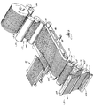
- Fig. 1 is a perspective view of apparatus 1 for manufacturing the present invention and showing a large number of continuous monofilaments 3 that are meltspun from a corresponding number of extrusion orifices in a spinneret 5.
- the extrusion orifices are arranged in an elongated rectangular arrangement, in one or more rows, or in one of many other configurations.
- the spinneret 5 is fed a fused polymer from a first extruder 7.
- the spinnerets may be arranged so that two or more spinnerets 5' oscillate as shown in Fig. 14. If two spinnerets 5' are 180° out of phase, the resultant web will consist of two layers of continuous filaments, each in a parallel sinusoidal patterned orientation, 180° out of phase with each other. If the filaments are closely spaced and have a sufficient oscillation amplitude, the molten filaments will overlap one another and form bonds at their cross over points. Alternately, the various spinnerets may be fed different polymers. In the construction of Fig. 14, the filaments 3 from the individual spinnerets 5' travel in zone 6 under ambient conditions. By the time the individual curtains of filaments come together at region 2, they have become solidified.
- the filaments 3 are drawn mechanically from the spinneret and enter a travel zone 9, which may be confined inside a covered chamber or chimney 10 so as to introduce cooled, ambient, or heated air or other gas at a controlled temperature as required for draw processing or at least partially solidifying the filaments.
- the extruded filaments travel to a temperature controlled accumulating roll 11 whereon a layer of melt blown fibers or filaments 12 is deposited and fused or self-bonded to the continuous melt spun filaments 3 by a first melt blown die 13 being fed a fused polymer from a second extruder 15.
- a conventional fiber blowing device or air former may be used to deposit either natural or manmade fibers of all types, including drawn or undrawn textile fibers.
- This fiber deposition may range in weight from less than one gram per square meter to several hundred grams per square meter.
- the stabilized web 16 passes over the guide device 17 and around the first feed roll 19, around the first draw roll 21, around the second draw roll 23, and finally around the third draw roll 25.
- the feed roll 19 and draw rolls 21, 23, and 25 are temperature controlled in order to meet all the conditions necessary for hot or cold drawing, heat setting, or annealing the filaments for high strength or other preferred properties and may have smooth or rough surfaces depending on how much slip is required for processing.
- the filaments need not be fully drawn, for it may be desirable to have some potential molecular orientation remain in the filaments so that in use or under load the filaments will stretch and be additionally drawn and molecularly oriented rather than exceed the elongation to break and rupture.
- the stabilized and drawn web 27 passes around idler roll 29 and onto chill roll 31, at which time a second melt blown die 33 being fed a second fused polymer from a suitable extruder 30, usually of a different melting point or range, deposits a second layer 35 of melt blown fibers on the stabilized web.
- the web 37 passes through a pair of crimping or stretch rollers 39, which impart an incremental stretch and crimp to the web, thereby increasing the draw and bulk of the melt blown fibers 12 and 35 and the continuous filaments 3.
- the drawn bulked and stabilized web 37 is deposited on a conventional cross lapping apparatus 41, as more fully described in U.S. Patent No. 3,183,557, which is also incorporated herein by reference, and cross lapped onto web 43 which is supplied from a parent roll 44 and is carried downstream by conveyor 45 on a non-stick foraminous conveyor belt 4.
- a conventional vacuum chamber 46 underlies the conveyor.
- the vacuum chamber 46 is connected to a vacuum supply via a duct 48.
- the continuous filaments of the cross lapped web 37 are now lying on web 43 in transverse directions to the conveyor travel, as indicated by arrow 52.
- the transverse angle may vary from 0° through 90°.
- the two webs 37 and 43, shown as composite web 50, are carried into heated embosser 47 of which one roll 49 is smooth.
- the upper embosser roll 51 contains a plurality of raised points that autogenously bond the cross lapped web 37 and the longitudinal web 43 together to form a single high strength, drapable web 53 containing a pattern of spot bonds.
- the pattern of autogenous bonds need not be symmetrical.
- Autogenous bonds are produced by the application of heat and pressure alone without any application of solvents or adhesives, whereas melt blown pressure sensitive adhesive fibers are able to form bonds with each other or to other fibers and filaments with only the use of pressure.
- the autogenous bonds may range from fusion bonds to stick or release bonds which retain filament identity upon separating or releasing under strain, and may extend through the web, thereby fusing all fibers and filaments in the bond area or may form fusion bonds with the fibers or filaments on the outer surface or surfaces.
- the spans between bonds contain substantially parallel filaments in a substantially controlled predetermined laydown alignment, the total numbers of spot bonds or total spot bond area between webs 37 and 43 can be reduced, with no reduction in web strength since the substantially parallel laydown is more uniform and stronger. This reduction in spot bonds reduces web stiffness, creating a more flexible web with increased hand and drapability.
- the raised points on the heated upper roll 51 may follow the construction disclosed in U.S. Patent 4,041,203.
- the cross laid or cross lapped longitudinal filaments may be bonded to each other or to other webs with melt blown fibers and/or filaments of hot melt adhesive fibers, pressure sensitive adhesive fibers, or viscoelastic hot melt pressure sensitive adhesive fibers, or a fine spray of ambient temperature liquid adhesives.
- one or more plies, mats, or layers of melt blown superfine thermoplastic fibers such as those described in "Industrial and Engineering Chemistry” may be laminated to one or more stabilized webs by passing the ply assembly through the heated embossing rolls 47.
- the stabilized webs may consist of only one web of stabilized longitudinal filaments or may consist of several layers, including cross lapped and/or cross laid webs.
- Fig. 17 shows a representative portion of a web 146 having spaced apart autogenous bonds 147 having spans therebetween consisting of two layers of substantially parallel or non-random laid filaments 148.
- the plies, mats, or layers of melt blown superfine thermoplastic fibers preferably have fiber diameters in the range of about 0.5 to 10 microns or depending upon the product being manufactured may be larger than 10 microns in diameter.
- One or more microfiber mats may be combined with one or more layers of stabilized webs and cross lapped or cross laid to produce fabrics for use as surgical gowns, drapes, and the like having excellent strength and drape or flexibility characteristics.
- the stabilized web is composed of continuous filaments in a substantially predetermined non-random lineal orientation with a controlled predetermined porosity, opacity, and uniformity of basis weight across the web, it is especially suitable for products requiring air permeability and liquid strike through resistance or water repellent characteristics such as surgical overwraps, sterile wraps, or containment fabrics for surgical or health care procedures.
- the stabilized web and the melt blown mats may be laminated by the deposition of melt blown fibers comprised of hot melt adhesives on either the mat or the web.
- the hot melt adhesives may also be of the pressure sensitive type or may be a viscoelastic hot melt pressure sensitive adhesive.
- the cross lapped continuous filament web 37 and the continuous longitudinal filament web 43 laminate may be passed between two heated belts under pressure, thereby holding the web 50 under positive restraint to prevent shrinkage, and heat bonded. After bonding, the web 53 is wound on a conventional winder 55, Fig. 1.
- adhesive may be applied to web 43 by means such as roller coating or spraying prior to cross lapping to facilitate the lamination of web 53 to one or more plies of cellulosic tissue or melt blown microfiber mat.
- Melt blown hot melt adhesive fibers can be deposited on the continuous filaments before, during, or after cross lapping or cross laying.
- the melt blown adhesive fibers can be of the hot melt type, pressure sensitive type, or any of the adhesives capable of being spun into fibers.
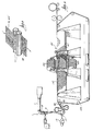
- apparatus 57 that directly supplies a web 43' to the conveyor 45 for cross lapping.
- the apparatus 57 comprises a spinneret 59 that is fed by an extruder, not shown.
- Filaments 61 are drawn from the spinneret 59 in curtain form.
- a die 63 continuously deposits melt blown fibers 65 on the curtain of filaments 61 to create the stabilized web 43'.
- the stabilized web 43' passes over feed roll 67, draw rolls 69, 71, 73, 75, and finally passes onto the conveyor 45.
- FIG. 3 alternate apparatus 77 is depicted for bonding cross laid webs.
- reference numeral 50' refers to the unbonded cross laid web of continuous substantially parallel filaments of polyamides and blends thereof, including melt blown polyamide fibers or filaments self-bonded to the continuous polyamide filaments.
- the webs 50 or 50' may pass through an activating gas chamber 79 as taught in U.S. Patent No. 3,516,900 by a conveyor system 81.
- the individual webs are self-bonded between two porous constraining belts 82 under heat and pressure by using the gaseous material to activate the bonding properties of the polymeric filaments and create the single high strength web 53'.
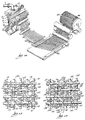
- rolls of stabilized continuous filament webs 83 are mounted on a cross layer 85 as shown in Fig. 4 and Fig. 5 and as disclosed in U.S. Patent No. 3,492,185, the disclosure of which is incorporated herein by reference.
- reference numerals 99 represent adhesive applicator rolls
- reference numerals 101 represent adhesive pans, both of which are well known in the art.
- a non-stick belt is shown at 102.
- the resultant web is illustrated at reference numeral 87.
- melt blown fibers lie after the cross lapping operation.
- the melt blown fibers are alternately above and under the cross lapped web.
- the melt blown fibers are on the exterior and the continuous filaments are in face to face relationship.
- the melt blown filaments are in face to face relationship.
- the filaments may be heat set on one or more draw rolls by heating the filaments at substantially constant length to impart dimensional stability thereto. They also may be cold stretched at substantially ambient temperatures or above but not exceeding about 100° C for polypropylene, followed by hot stretching at a temperature above about 120° C, but below the fusion temperature, without allowing shrinkage of any significant degree to their cold stretched length.
- differential drawing, crimped or incremental drawing, and mechanical drawing using draw rolls with variable surface temperatures and surface roughness variations from smooth to rough may be performed.
- one or more modulating rolls 89 are used prior to a melt blown deposition of fibers or filaments 12' on the curtain of filaments 3'.
- reference numeral 93 indicates a chill roll.
- the modulating rolls 89 reciprocate in transverse directions, as indicated by arrow 91, to place the parallel lineally oriented filaments in a patterned parallel orientation or in a patterned overlapping orientation.
- the terms “parallel,” “approximately parallel,” and “substantially parallel” are herein used interchangeably and are intended to describe the alignment patterns of continuous filaments within the practical limits of machine lay down on a roll or belt in a substantially parallel alignment with each other.
- This alignment may be in a curvilinear sinusoidal, zigzag, or other pattern and may be in one or more layers of overlapping patterns.
- the resulting web 94 is thus composed of generally longitudinally extending sinusoidal patterned continuous filaments 3' and the melt blown fibres 12'. These patterns can zigzag in linear or curvilinear orientation.
- a typical portion of the resulting web 95 is shown in Figure 7a.
- two oppositely reciprocating modulating rolls can be used in a manner that produces double sinusoidal patterns that are out of phase.
- the web takes on the general appearance shown at 95' in Fig. 7b.
- the web can be incrementally drawn with minimum distortion to the continuous filament orientation.
- a pair of corrugated draw rolls 97 may be used to incrementally draw the composite web 16 or 43' of the melt spun partially drawn continuous filaments and melt blown substantially undrawn stabilizing fibres.
- the incremental drawing causes minimum distortion to the filament orientation and creates a stabilized web 98 of a drawn filamentary curtain and fibres.
- a fibre-forming thermoplastic polymeric resin is extruded in molten form through orifices of heated nozzles of the die 13 at temperatures within the range of about 250°-900°F (121°C-482°C) into a stream of hot inert gas at temperatures of about 250°-1000°F (121°C-538°C) to attenuate the molten resin as fibres or filaments 12, which are then deposited in a molten form onto a curtain of molecularly orientated continuous filaments 3 having a low degree of crystallinity, forming self-bonds at their intersections or crossover points.
- Hot melt adhesives including pressure sensitive hot melts can be melt blown using air temperatures as low as about 250°F (121°C).
- the various parameters for self-bonding with a minimum of increased crystallinity in the continuous filaments are the distance from the melt blown nozzles to the continuous filamentary curtain, the deposition temperature of the melt blown fibres or filaments at the instant of contact with the continuous filaments, the diameters of the melt blown fibres or filaments as compared to the diameters of the molecularly orientated continuous filaments, and the time the continuous filaments are subjected to the fusing self-bonding temperatures.
- melt blown polypropylene fibres or filaments having diameters of about 3 to 12 microns were satisfactorily self-bonded to drawn molecularly orientated continuous polypropylene filaments having diameters ranging from about 50 to 100 microns, at a die-to-curtain distance of 6 inches to 10 inches (15.2 to 25.4 cm) under ambient conditions.
- This die-to-curtain distance can be varied to accommodate various combinations of melt blown fibre and filament diameters in conjunction with various continuous filament diameters, the various melt blown fibre deposition temperatures, and the variations in the ambient air cooling or quenching conditions at the die nozzle exit in the quench chamber 10.
- These fibers or filaments can be molecularly oriented by drawing incrementally or otherwise in one or more directions. If the continuous molecularly oriented filaments have been subject to too high a temperature at the bonding intersections, they lose their molecular orientation in the bond area. This over-bonding, with its accompanying excessive fusion, adversely affects the web tensile characteristics and usually occurs when the melt blown molten fibers or filaments 12 are large as compared to the molecularly oriented continuous filaments 3 in the curtain. This can be seen in Fig. 10 wherein the continuous filament diameters are approximately 10 to 12 microns and the hot molten melt blown fiber or filament diameters are approximately 40 to 50 microns.
- the continuous filament curtain is stabilized with a deposition of melt blown molten fibers or filaments of a second polymer which may or may not be compatible with the polymer of the continuous filaments; that is, having the ability to form fusion or melt bonds with the continuous filaments without continuous filament degradation at bond intersections.
- the melt blown fibers are deposited on the continuous filaments supported by a temperature controlled accumulating roll which prevents the continuous filaments from becoming overheated.
- the distance from the melt blown spinneret to the temperature controlled accumulating roll can be varied so that the temperature of the melt blown fibers or filaments can be kept such that the increase in crystalinity in the continuous filaments will not be high enough to adversely affect the continuous filament tenacity, even though the surface of the continuous filament is softened to the tacky state.
- the temperature controlled accumulator may be a roll, belt, or a stationary bar depending upon the tackiness of the emerging polymer, and may be foraminous depending upon the volume of high velocity air needing to be dispersed.
- the polymers are incompatible, they form releasable bonds which are strong enough to give the stabilized filamentary curtain enough integrity to carry it through the downstream drawing and bonding operations, even though some of the bonds release under strain.
- the use of different polymers in the melt spun continuous filaments and the melt blown fibers or filaments facilitates the laminating and bonding of two or more layers of the stabilized double polymer filamentary web.
- the attaching of the two webs can be accomplished by fusion bonding the melt blown fibers or filaments with each other without raising the temperature of the continuous filaments to the softening point wherein an increase in filament crystalinity has an adverse effect on the web tenacity.
- This two-polymer filamentary web can now be cross lapped and laminated as in Fig. 1 and Fig. 2 or may be cross laid as previously described and shown in Fig. 4 and Fig. 5.
- the cross lapped or cross laid webs can be laminated to one or more plies of cellulosic tissue or to one or more plies or mats of super fine melt blown micro-fibers having diameters in the range of about 0.5 to 10 microns with the use of melt blown adhesives such as hot melts, pressure sensitive hot melts, or viscoelastic hot melt pressure sensitive adhesives.
- melt blown fiber diameters may be larger than 10 microns depending upon product requirements, and the laminating adhesives are not limited to melt blown fibers. It is preferred that about three percent or more of any of the stabilizing melt blown fibers are self bonded at the junctions with each other or with the continuous filaments.
- melt blown fibers or filaments 12 are deposited on freshly spun continuous filaments 3 as they are being drawn. That process forms an improved bond since a fresh new surface is exposed by drawing.
- Molten melt blown dissimilar polymers and incompatible polymers form release or stick bonds strong enough to withstand downstream laminating operations.
- These melt blown polymers may have melting points or ranges above or below the melting point or the melting range of the continuous filaments, which serves to increase the number of bonds in plied bonded webs, as in Figs. 11 to 13, when autogenously bonded by a pair of heated rolls, one of which has raised points on its surface as previously described and shown in Fig. 1.
- Fig. 11a shows a first web 103 of stabilized continuous filaments 105 to which are bonded the melt blown fibers 107.
- a second web 109 is comprised of the continuous filaments 111 and melt blown fibers 113.
- the webs 103 and 109 are oriented such that the filaments 105 are placed at right angles to the filaments 111.
- the two webs are placed together such that the continuous filaments 105 and 111 are in facing contact. Bonding the individual webs results in the composite web 115 of Fig. 11c, which comprises two curtains of stabilized continuous filaments bonded together at 90° to each other in face-to-face relationship.
- Figs. 12a and 12b show webs 116 and 117, respectively.
- Web 116 is composed of continuous filaments 119 stabilized by fibers 121
- web 117 is composed of continuous filaments 123 stabilized by fibers 125.
- the filaments 119 and 123 are positioned transversely to each other at an angle of less than 90°, with the filaments 119 and 123 in facing contact.
- the two webs 116 and 117 are then bonded together such that the melt blown filaments are in facing contact to create the two-ply web 127 of Fig. 12c.
- the assembly of these webs may be accomplished in one of three ways as follows: 1) the stabilized continuous filaments of a first web being in face-to-face relationship with the continuous filaments of a second stabilized web; 2) the melt blown fibers of a first stabilized web being in face-to-face relationship with the melt blown fibers of a second stabilized web; 3) the melt blown fibers of a first stabilized web being in face-to-face relationship with a filamentary curtain composed of continuous filaments of a second stabilized web.
- reference numeral 129 refers to a web of continuous filaments 133, stabilized by fibers 134, that have been incrementally drawn.
- Web 131 of Fig. 13b is composed of incrementally drawn filaments 135 that are stabilized by fibers 136.
- the filaments 135 are transversely positioned at 90° to the filaments 133 of web 129. Bonding the filaments 133 and 135 of the webs 129 and 131, respectively, to each other in face-to-face relationship at 90° results in the exceptionally high bulk two-ply web 137 of Fig. 13c.
- melt blown fibers 35 may be deposited on cooled molecularly oriented continuous filaments 3 that are partially wrapped around a chill roll 31.
- the melt blown fibers are cooled or quenched rapidly in a relatively undrawn state with low tenacity.
- the melt blown fibers become oriented in various degrees with increased tenacity as described in U.S. Patent No. 4,153,664 discussed earlier.
- the drawn continuous filaments are put under strain, such as by the wearer of a diaper, the melt blown fibers are further drawn to shift the strain onto joining filaments.
- melt blown fibers were undrawable, they would break when the developed stress exceeded their tenacity, thereby increasing the strain on the continuous filaments, which after reaching the breaking point would have reduced effective lengths over which they could carry an applied strain.
- This property of the melt blown fibers to attenuate under load or strain enhances the softness, drapability, surface smoothness, and fabric like feel necessary for light weight fabrics used in disposable products, and shifts or distributes the strain over a large number of continuous filaments.
- molecularly oriented continuous filaments in combination with stretched elastomeric continuous filaments are subjected to a deposition of molten melt blown polymers and kept under tension until the self bonding melt blown fibers and/or filaments have solidified, thereby stabilizing the web in a stretched and drawn condition.
- the elastic filaments contract, and the web shortens in the direction of elastic filament contraction. This contraction forms buckles or wavy curls or kinks in the substantially parallel, non-random, molecularly oriented continuous filaments between the foreshortened bond spacings.
- Fig. 20 depicts a representative portion of a stabilized web 150 of the present invention showing the continuous elastic filaments 151 that have contracted somewhat, but that still are under a light tension, together with non-elastic molecularly oriented continuous filaments 153.
- the web 150 is stabilized by the melt blown filaments 155.
- the curls or buckles vary in shape and size depending on the placement of the elastomeric filaments and the proportions of elastomeric filaments to the molecularly oriented filaments 153.
- a resultant laminate or fabric is obtained which has a very high bulk and is very light in weight. Its high bulk makes it very useful for disposable garments because of its increased opacity.
- the melt blown fibers and/or filaments may be either a molecularly orientable polymer, a stretchable elastomeric polymer, or a melt blown polymeric adhesive.
- elastomeric continuous filaments are stretched and kept under tension while depositions of melt blown elastomers or other spinnable polymers are deposited in face-to-face relationship, thereby producing stretchable webs of variable restretch characteristics.
- a curtain of continuous filaments of a higher melting temperature than the melt blown fibers is locked in place or constrained in a predetermined orientation, with a deposition of self-bonding melt blown fibers on each side of the curtain, which are fusion-bonded or self-bonded.
- the bonding of melt blown fibers to the continuous filaments vary from no bonds to stick bonds.
- the melt blown fibers form bonds with each other varying from fusion bonds to releasable bonds yet are able to constrain and hold the continuous filaments in predetermined alignment until processed into the final web.
- Melt blown webs as low as 2 to 4 grams per square meter have satisfactorily locked and held continuous filaments in place during various processing procedures.
- melt blown fiber basis weight for stabilizing an array of filaments is in the range of about 5 to 10 grams per square meter with no limit on the maximum basis weight of melt blown fibers deposited on heavier basis weight webs. Since the melt blown fiber stabilizing deposition has a very low basis weight with respect to the filamentary array, slight variations in its random laydown deposition have little if any effect on the porosity, opacity, and uniformity of the basis weight across the final web.
- fusion-bonding or “self-bonding” are used herein interchangeably, and are brought about by molten surface filament-to-fiber fusion.
- releasable bonds and “stick bonds” are used herein interchangeably and are fusion or autogenous bonds of a temperature low enough to allow filaments to separate or pull free from each other without breaking, or bonds between incompatible materials, which, due to their chemical structures or their variances in melting points or ranges, form weak, stick, or releasable bonds.
- drawn and “molecularly oriented” are used herein interchangeably.
- Fig. 15 is a magnified view of continuous filaments 138 locked in place by fusion bonds of the melt blown fibers 140 to each other at points 139 and by fusion bonding of the melt blown filaments to the continuous filaments at 141.
- the continuous filaments 138 are shown autogenously bonded to other continuous filaments and to melt blown fibers at points 143.
- a magnified view of continuous filaments 138' locked in place between fusion bonded melt blown fibers 140' is presented.
- the continuous filaments 138' are constrained in substantially parallel or substantially non-random orientation.
- the continuous filaments are locked in place by fusion bonding of melt blown fibers 140' to each other at points 139'. Autogenous bonding occurs at typical points 143'.
- some stick or released bonds, or no bonds with the continuous filaments occur at points typified at reference numeral 145.
- non-woven webs are provided that possess the conformability and drapability of woven fabrics made from the same filaments.
- the non-woven web is comprised of continuous filaments having no bonds at their intersections. Accordingly, as with woven fabrics, the continuous filaments of the non-woven web are free to slide and slip relative to each other when the web is deformed or draped over an object.
- a magnified portion of a non-woven web 311 having substantially parallel cross laid continuous filaments 313 and 315 is illustrated.
- the continuous filaments 313 and 315 are stabilized to form the web 311 by means of small diameter melt blown fibers 317.
- the melt blown fibers 317 are fusion bonded intermittently to the continuous filaments along the lengths thereof, as at points 319, on one side of the continuous filaments.
- the melt blown fibers may be deposited on and fusion bonded to both sides of the continuous filaments.
- melt blown fibers having a lower fusion temperature than that of the continuous filaments may be deposited on both sides of the continuous filaments.
- the melt blown fibers fuse only to themselves, and they trap the continuous filaments in a parallel arrangement.
- the web 311 is in a relaxed condition.
- the continuous filaments slide over one another, as shown in Fig. 22.
- typical continuous filament 315b is shown in a location displaced from the location 315a of Fig. 21 due to deformation of the web.
- Relative movement of the continuous filaments 315 causes associated movement of the weaker melt blown fibers 317.
- the melt blown fibers typically represented at 323a in Fig. 21 become stretched to the respective conditions represented by reference numerals 323b in Fig. 22.
- melt blown fibers such as fibers 325a in Fig. 21, become relaxed to the condition represented by reference numeral 325b in Fig. 22. If the melt blown fibers are of a drawable polymer, they will become molecularly oriented upon stretching when the web is deformed.
- the present invention is based on the discovery that stabilization of molecularly oriented continuous filaments having laydown patterns ranging from substantially parallel orientations to random orientation including predetermined curvilinear, zigzag, or various overlapping orientations with melt blown molten drawable fibers forms an integral web which, when subjected to overloading, strains deforms and stretches by the additional drawing or molecular orienting of the partially oriented melt blown fibers, thereby shifting the overloading strain over a larger number of continuous filaments rather than rupturing the web.
- the stabilized molecularly oriented continuous filament web is processed by cross lapping, cross laying, or laid-up in two or more plies which are then subjected to a spot bonding operation by passing it through two heated rolls, one of which has a plurality of projections on its surface, the shape of which may be square, rectangular, round or some similar shape.
- the web, subjected to heat and pressure of the embossing rolls, has formed on it discrete compacted areas of sizes and shapes determined by those of the roll projections, wherein the fibres and filaments have been autogenously bonded together. It has been found that the higher the number of compacted areas per unit area in a web, and the higher the percentage of compacted area, the stiffer the web will be, with deleterious effect on drapability, softness, and clothlike feel and appearance.
- non-random refers to the laydown patterns of filament alignments which are in a substantially predetermined alignment and have a substantially controlled basis weight and opacity, as opposed to the random laid filaments previously described. Previous laydown methods do not have precise control of filament laydown and positioning. These patterns may be many and various and in different layers throughout the web.
- the predetermined alignments may be wavy, zig zag, or sinusoidal, and various layers may cross and overlap one another. Since the random laid melt blown fibers represent a much smaller proportion of the total web weight, they have little or no noticeable effect on the overall basis weight or web opacity. Satisfactory webs have been produced having random laid melt blown stabilizing fibers with basis weights as low as 1 to 3 grams per square meter.
Landscapes
- Engineering & Computer Science (AREA)
- Textile Engineering (AREA)
- Chemical & Material Sciences (AREA)
- Chemical Kinetics & Catalysis (AREA)
- General Chemical & Material Sciences (AREA)
- Nonwoven Fabrics (AREA)
Description
- The present invention relates to a non-woven laminate and to a method of making same.
- Non-woven webs comprising a plurality of substantially continuous and randomly deposited, molecularly orientated filaments of thermoplastic polymers are widely known in the art and are finding widespread commercial use. However, there is a great need for non-woven webs having a higher uniformity, better hand, greater strength and a better control of the uniformity of the molecular orientation of the individual filaments than are presently available.
- Until the instant invention, non-woven webs have been prepared by simultaneously spinning a multiple number of continuous filaments of a synthetic polymer such as polypropylene through a multiple number of spinning nozzles or spinnerets, preferably extending in one or more rows. The filaments are simultaneously drawn through air guns, eductors, or air jet drafters (air suckers) at high velocities in individually surrounding gas columns directed by exit nozzles to impinge on a moving collector, in loop like, overlapping arrangements, where they form a continuous non-woven random laid web which may be consolidated, compacted and stabilized by various bonding techniques such as hot calendering, autogenous spot bonding by passing the web between heated patterned embossing rolls, needle punching, or treating with suitable binders.
- The filaments are drawn downwardly at velocities of approximately 600 to 8000 meters per minute in surrounding gas columns flowing at supersonic velocities and impinging on a horizontal carrier which is moving at speeds generally in the range of 150 to 300 yards per minute (137-274 m/min). This low ratio of web production capability to the filament output results in a relatively uncontrollable random laydown of the filaments with an accompanying adverse effect on the uniformity of strength, opacity, drapability, and soft fabric-like hand. After formation on the carrier, the web is passed between two rollers and lightly compacted prior to passing through the pressure nip of two heated rolls, one of which contains a plurality of raised points on its surface. The amount of prewrap and the roll temperature is critical in that too high a web temperature results in high web shrinkage, film forming effects and over-bonding with its adverse effect on drapability, and can also result in filament degradation with an accompanying reduction in filament tenacity. If the web temperature is too low, the filaments release from their bond points before any substantial strain is applied to the filaments allowing the web to slither apart.
- Prior methods of preparing the continuous filament webs have at least three common features.
- 1. Continuously extruding a thermoplastic polymer, either from a melt or a solution, through a spinneret in order to form discrete filaments.
- 2. The filaments are drawn or drafted by high velocity air in order to molecularly orient the polymeric filaments and achieve tenacity.
- 3. The filaments are deposited in a blast of high velocity air or gas in a substantially random manner onto a carrier belt or the like to form a web with substantially isotropic physical characteristics.
- The prior webs all have one thing in common and that is that the filaments are all laid in a loop-like random arrangement onto a carrier belt or the like with high velocity air to form a web. Accordingly, they are all subject to the problems associated with air formed webs, such as turbulent air flow with resultant filament intertwining, and plugging of eductors by broken filaments or molten polymer, all of which impart an undesirable non-uniformity in appearance, drapability, tensile strength, opacity, basis weight, and variations in degree of filament entanglement. Variations in the gap space of air jet slits results in non-uniform flowing action of air jets on filaments, resulting in non-uniform webs. Slight variations of the conditions for cooling destroys the uniformity of distribution of the filaments, and difficulties of getting all eductors or air channels to produce filaments having the same characteristics are manifold. The drapability is poor due to the high numbers of autogenous spot bonds required to form a coherent structure and web of commercial integrity. Also, the installation costs and maintenance expenses, and the required capital investment in air handling equipment and ducting for the high volumes of high pressure heated air required for the blasting action of the air jets on the filaments to draw and deposit them on the collecting device are immense. The above described methods require high air consumption of heated air, which in turn consumes huge amounts of power.
- US-A-3,449,187 discloses a method of making non-woven fabric in a continuous sequence of operations by extruding a curtain of thermoplastic resin filaments which are then stretched to cause orientation of the resin molecules. The curtain, still in tacky condition, is then contacted on at least one side thereof with a layer of evenly disbursed staple fibres and the filaments and staple fibres are pressed together and cooled to form an intermediate composite web. This composite web is then warmed up and contacted with additional extruded curtains of thermoplastic resin filaments which are orientated by stretching and superimposed with further layers of evenly disbursed fibres and the obtained combination is compressed and cooled to form the non-woven fabric which is wound on a roll.
- GB-A-2,126,162 discloses a non-woven fabric of continuous thermoplastic filaments which are melt blown.
- According to one aspect of the present invention, there is provided a non-woven laminate comprising at least two webs (37,43) with one web formed of a multiplicity of molecularly orientated substantially parallel continous filaments (3,148,158) of a thermoplastic polymer, said multiplicity of continous filaments being stabilised by melt blown fibres (12,35) and wherein the other web is also formed of a multiplicity of substantially parallel continous filaments characterised in that the melt blown fibres (12,35) are deposited on the continous filaments and one web is crossed on the other so that the filaments of the one web transverse to the filaments of the other web said filaments being intermittently united by bonds (141,157) at a plurality of spots, so that some of the filaments of each web are unbonded to and free to slide relative to the filaments of the other web.
- According to another aspect of the present invention, there is provided a method of forming a non-woven laminate (53) comprising at least two webs (37,43) with one web formed of a multiplicity of molecularly orientated substantially parallel, continous filaments (3,148,158) of a thermoplastic polymer, said multiplicity of continous filaments being stabilised by melt blown fibres (12,35) characterised by comprising the steps of:-
- (a) forming said filaments by spinning molten polymer streams and mechanically drawing said filaments,
- (b) directing a first air stream containing said melt blown fibres (12) in a molten state onto a first side of the multiplicity of drawn filaments, thereby forming bonds at cross over points of the melt blown fibres and locking in place the filaments to produce a stabilised web (16) of the filaments and fibres, said air stream having a temperature in a range of about 250 F (121 C) to about 900 F (482 C);
- (c) overlaying said stabilised web with a second web to form a composite web (50) of transversely crossing plies of drawn filaments onto a conveyor (45),
- (d) autogenously bonding the cross-laid plies together in discrete compact areas (141,151; and
- (e) collecting said autogenously binded composite web in the form of a said non-woven laminate (53).
- It is proposed in one embodiment to form an integral filamentary web comprising continuous filaments and melt blown fibres or filaments in order that the various drawing, heat setting, and other processing variables can be handled in a web form rather than as individual filaments, thereby eliminating tension, stripping, and restringing problems. Broken continuous filaments are automatically picked up by adjacent molten continuous filaments, and continue along as an integral part of the web. The stabilized web is pulled from the exit draw roll by a cross lapper, cross layer, heated embossing rolls, or a conventional winder, any of these methods being capable of applying various degrees of tension to the web depending upon the nature of the final product. As shown FIG. 6, the longitudinal filaments 3' are oscillated laterally by modulating
roll 89 and deposited onchill roll 93 in a relaxed, untensioned state prior to a deposition of melt blown fibers or filaments 12' which lock the longitudinal filaments in a parallel lineally oriented laydown pattern. However, the preferred method is to process the web including the cross laying steps with the longitudinal filaments under tension and molecularly oriented to the desired degree. If the filaments are elastomeric and under tension they will be in the stretched state. If the filaments are a mixture of elastomeric and drawable polymeric filaments, the elastomeric filaments will be under tension and stretched, and the drawable polymeric filaments will be under tension with the polymer molecules oriented in the direction of the filament axis. After stabilizing with melt blown fibers and upon relaxing, the elastic filaments contract and the web shortens in the direction of the elastic filament contraction, thereby forming buckles and curls or kinks in the non-elastic molecularly oriented permanently lengthened continuous filaments. The forming of a stabilized web by the deposition of melt blown fibers allows the array of individual filaments to be further processed as an integral web, obviating the need for aspirators, eductive devices such as eductive guns, noneductive devices, and including the application of static high voltage to filament groups. The handling of a multitude of continuous filaments, having a predetermined controlled alignment, as an integral web during the various finishing operations eliminates the previously stated problems, such as turbulence problems, filament intertwining, plugging of eductors by broken filaments and non-uniform basis weight, opacity and porosity. The laydown patterns of the continuous filament alignments across the web are in a substantially predetermined controlled alignment, thereby providing the web with a controlled predetermined porosity, opacity, and a uniform basis weight throughout the web. The basis weight of the melt blown web or fibres may be as low as about 3 to 5% of the final web basis weight and has a negligent effect on the opacity, porosity, and basis weight of the web. - In actual practice random laid webs rarely, if ever, reach complete randomness, and as a result are not completely uniform in appearance. This non-uniformity detracts from its suitability as filters, medical fabrics, and the like, which require a low degree of variations in porosity, basis weight and opacity. Since aspirators, eductors, non-eductive arrangements and the like do not precisely control the laydown patterns of individual filaments in predetermined controlled laydown alignments, the final web is subject to the aforementioned variables.
- In one embodiment, the melt blown fibres are deposited in a molten state onto the curtain of partially coagulated and partially drawn continuous filaments immediately upon exiting from the spinneret and subsequently drawn again according to predetermined conditions.
- In another embodiment, the drawable melt blown fibres or filaments are deposited and self-bonded to the curtain of continuous filaments after the continuous filaments have been partially drawn upon exiting from the spinneret, cooled to the solid state, and subsequently drawn according to predetermined conditions.
- In another embodiment, the molten melt blown fibres or filaments are deposited onto the curtain of continuous filaments after they have been fully drawn either pneumatically or mechanically, and in another embodiment the melt blown fibres and/or filaments are deposited on the continuous filaments as they are being drawn, as will be subsequently discussed in more detail. These air blown fibres may include both natural and manmade fibres of all types, including wood pulp, cotton, hemp, rayon, sisal, and drawn or undrawn textile fibres.
- In an alternate arrangement, streams of melt blown fibres are merged with streams of cellulose fibres and/or super absorbent polymeric particles prior to deposition on the stabilized web to form a high bulk highly absorbent fabric.
- The thermoplastic melt blown fibers or filaments used herein for stabilizing a curtain of continuous filaments can be prepared by known techniques as described in an article by Van A. Wente entitled "Superfine Thermoplastic Fibers" appearing in Industrial and Engineering Chemistry, Vol. 48, No. 8, pp 1342 to 1346. The fiber diameters may vary from 0.5 to 50 or more microns depending upon the combination of gas flow rates, polymer flow rate, die temperature and polymer molecular weight. Their lengths may vary from short fibers to substantially continuous length filaments depending upon the air temperature and velocity and the distance from the die to the collector.
- The terms "melt blown fibers," "melt blown filaments," and "melt blown fibers and/or filaments" are herein used interchangeably. The term "continuous filament" as used herein refers to the melt spun filaments formed from a number of orifices in a spinneret plate and are continuous. The terms "continuous filament" and "melt spun filaments" are herein used interchangeably.
- Among the many thermoplastic polymers suitable for use in stabilizing the above filament curtain are polyolefins such as polypropylene, polyethylene, polybutane, polymethyldentene, ethylene-propylene copolymers; polyesters such as polyhexamethylene adipamide, poly(oc-caproamide), polyhexamethylene sebacamide; polyvinyls such as polystyrene; thermoplastic elastomers such as polyurethanes; other thermoplastic polymers such as polytrifluorochloroethylene and mixtures thereof; as well as mixtures of these thermoplastic polymers and copolymers; also included are viscoelastic hot melt pressure sensitive adhesives such as "Fullastic" supplied by H.B.Fuller and Co., and other hot melt adhesives including pressure sensitive adhesives. Any of the fiber forming thermoplastic polymers including fiber forming hot melt adhesives, pressure sensitive adhesive, and viscoelastic hot melt pressure sensitive adhesives can be used for stabilizing the web or bonding the stabilized web to one or more cellulose webs, wood pulp webs, melt blown fibrous mats, or for laminating and bonding two or more stabilized webs to form laminates. The instant invention is not limited by the above polymers, for any thermoplastic polymer, copolymer, or mixture thereof capable of being melt blown into fibers or filaments is suitable. Any of the thermoplastic elastomers which are capable of being melt blown or melt spun is suitable for the manufacture of stretchable fabrics.
- In the preferred embodiments, thermoplastic melt spun continuous filaments are used which involve continuously extruding a thermoplastic polymer through a spinneret thereby forming a curtain of individual filaments. Among the many thermoplastic polymers suitable for the continuous filaments are polyolefins such as polyethylene and polypropylene; polyamides; polyesters such as polyethylene terepthalate; thermoplastic elastomers such as polyurethanes; thermoplastic copolymers; mixtures of thermoplastic polymers; copolymers and mixtures of copolymers; as well as the previously listed materials used herein for the melt blown fibres and filaments. However, the present invention is not limited to these materials for any melt spinnable polymer is suitable, including various tar products obtained from or produced as by-products from fossil fuels that are spinnable into carbon fibres. Other spinnable thermoplastic elastomers which are suitable for stretchable fabrics are polyester based polyurethane; and polyester type polyurethane polymeric fibre forming elastomers such as Texin 480A supplied by Mobay Chemical Company, but not limited to these.
- A method or process may be provided for the manufacture of non-woven webs according to an embodiment of the invention to provide increased strength from continuous filaments which have been molecularly oriented to a high degree under closely controlled drawing and temperature conditions and formed into a web of substantially parallel continuous filaments, and which can be used to ply up webs of two or more plies with the various webs having their filaments plied in a transverse direction to each other, the transverse angles varying from 0° to 90°. The continuous filaments of one layer may have a substantially parallel orientation in the machine or longitudinal direction with an adjacent layer having continuous filaments in substantially parallel orientation at a 90° transverse angle. However, if two layers of continuous substantially parallel filaments are biased at equal opposite transverse angles of between 0° and 90° the layers will be mirror images of each other. Since the angle of bias may vary from layer to layer, it should be noted that mirror images are not always necessary or needed. The continuous filaments of one layer may be the same or different than the continuous filaments of another layer or the continuous filaments in a single layer may be different from one another. In some cases, the layers may be composed of 100% elastomeric filaments or the layers may be composed of a combination of continuous elastomeric filaments and continuous filaments of another drawable polymer, stabilized with melt blown elastomeric polymers.
- The spinning and drawing of continuous filaments may be coupled with their stabilization to form a curtain of continuous filaments having a predetermined laydown orientation ranging from a substantially parallel orientation to a random orientation including curvilinear, zigzag, or various overlapping orientation, the filaments being drawn mechanically or pneumatically.
- In order to stabilize or fix in a predetermined orientation a multiple number of continuous filaments in a curtain form a layer of melt blown filaments or fibers may be deposited before, during or after drawing to molecularly orient the continuous filaments.
- An advantage of at least one embodiment of this invention is to create a novel web which is charaterized by a lineal substantially parallel alignment of continuous filaments which imparts to the web a woven appearance coupled with a uniform opacity, drapability, soft textile-like hand and superior strength.
- A more specific object is to increase immeasurably the numbers of fusion or self-bonds on the continuous filaments by depositing and fusing or self-bonding to the continuous filaments a layer of molten melt blown fibers while decreasing the density of autogenous embossed spot bonds and increasing the web tensile properties with the use of a substantially parallel filament laydown, resulting in a better hand and cloth-like appearance. Non-woven fabrics generally have not been used for clothes for the simple reason that as the strength of the fabric is increased the draping properties are decreased. The strength of the fabric can be increased by increasing the number of spot bonds or applying a large amount of bonding resin to the filamentary layer, which in turn results in inhibition of the movement of the filaments with one another, an increased resistance to deformation, and a resultant decrease of the draping properties of the fabric. Since a complete randomness is rarely accomplished in a random laid web, which can be seen by its non-uniform appearance and variability of the swirling, looping, overlapping arrangement of the filaments, especially in light weight webs, it becomes necessary to increase the number of spot bonds or compacted areas to form a coherent structure or web of commercial integrity, which in turn results in poor drapability. To overcome the increase in stiffness, many attempts have been made to soften the web by working and stretching the web in one or more directions, which have met with a limited success at an increased cost.
- In the instant invention, increased strength with good drapability is obtained by providing spans between spot bonds or melt blown fiber bonds, consisting of numerous continuous, longitudinal, substantially parallel filaments which act simultaneously to absorb applied loads or forces thereby eliminating the necessity for larger densities or numbers of spot bonds or compacted areas which in turn decreases the draping qualities of the fabric. In a web consisting of two or more face to face layers of continuous, substantially parallel and straight filaments lying transversely to each other, the load or transmitted force is distributed among several continuous filaments in a relatively straight line through bond points or compacted areas. In prior art random laid webs, the filaments are deposited in a looping, swirling, and overlapping fashion, wherein the tension force is applied to curved and looped filaments, between the spot bonds or compacted areas, and the filaments are bonded to each other obliquely in the compacted areas where the filaments are deformed and weakest. As a result of the looping and swirling laydown there are few, if any, straight filaments between widely spaced or low density bond points with the result that the load is applied to the filaments, one at a time rather than simultaneously as in the instant invention, and wherein the first filament to be loaded receives the greatest stress. In addition, the oblique tensions on the compacted areas of prior webs further increase the stress. See Fig. 19, which shows a representative portion of a random laid conventional non-woven web 301 having closely spaced
autogenous bonds 303 having spans consisting of substantially random laidfilaments 305. To form a coherent web the bond spacings have to be decreased thereby increasing the total compacted area of the web, and decreasing the ability of thefilaments 305 to slide and move with respect to one another during web deformation, all of which decreases the drapable properties of the web 301. - Woven fabrics having no bonds at their continuous filament intersections have increased drapability and are more conformable than non-woven webs having like filaments with bonds at their intersections. When these woven fabrics are deformed or draped about an object, the continuous filaments slip and slide at their intersections since the said intersections are not bonded, and as a result have increased drapability. Conventional random laid continuous filament non-woven webs have no coherency or strength unless they are bonded in some form or manner with a resultant increase in stiffness and decrease in drapability. It will be appreciated that there may be provided a non-woven web or method for making said non-woven web according to an embodiment of the invention comprising continuous substantially parallel filaments which approach more closely a supple, flexible woven web having no bonds at their filament intersections, than has heretofore been possible with prior art methods. The said web may be provided with bonded continuous filament widely spaced and variable intersections intermingled with non-bonded continuous filament intersections in various proportions to provide said web with various degrees of suppleness. These bonds may consist of autogenous spot bonds, using heat and pressure, or any other suitable form of bonding.
- The forming of substantially parallel continuous filament non-woven webs having no bonds at the continuous filament intersections or various combinations of bonded intersections combined with intersections having no bonds, which allow the said continuous filaments to slide or creep over one another as they do in woven fabrics, facilitates the ability to produce and substitute lower cost non-woven webs for the more expensive woven webs in an increasing number of markets. The continuous filament spacings may vary from wide spaces between filaments to webs wherein the continuous parallel filaments are so dense they touch one another.
- The parallel continuous filaments need not be bonded to each other at their intersections, but, rather may be stabilized in a web form by a deposition of fusion bonded smaller diameter melt blown fibers, having a lower tensile strength, on one or both sides of the continuous filament curtain. These smaller lower tensile strength fibers are fusion bonded intermittently along the lengths of the continuous filaments, or alternately, melt blown fibers of a lower fusion temperature than said continuous filaments may be deposited on both sides of said continuous filamentary curtain resulting in the melt blown fibers fusing to themselves only, since their fusion temperature is too low to fuse with the continuous filaments, thereby trapping or constraining the continuous filaments in a parallel filamentary arrangement.
- This filamentary web may now be further processed by cross lapping or cross laying into webs having no bonds at intersections of the continuous filaments, or may be bonded at least at some of the continuous filament intersections with the use of heat and pressure spot bonding, or other forms of intermittent bonding. This additional bonding increases the fabric strength and facilitates the lamination of various assemblies of webs. The bond patterns and their spacing may be such that there is a minimum of or no deleterious effect on the web or fabric suppleness.
- In the case wherein the parallel non-woven filaments are connected to each other by fusion bonded smaller diameter melt blown fibers which allow the said continuous filaments to slide over one another at their intersections when the web is deformed, the finer, weaker, low molecularly oriented fibers bend, move, or when elongated undergo molecular orientation with relatively low forces when said web is deformed. If elastomeric fibers are used stretching takes place upon web deformation.
- In cases where stiffer more rigid webs or fabrics are required, they may be obtained by bonding a majority or all of the continuous filament intersections in a heated calender stack having at least two rolls, at least one of which is heated and temperature controlled. One such laminate consists of at least two non-random arrays of continuous filaments, at least one of which is stabilized with a deposition of melt blown fibers, the arrays being positioned in laminar face-to-face relationship and separated by at least one deposition of melt blown fibers and passed through the laminator and laminated together so that the longitudinal filaments of one array is transverse to the filaments of the other array. If the melt blown fiber deposition layer is dense with no voids or apertures, the continuous filaments will be bonded predominently at or near their intersection areas. As the melt blown fiber deposition layer becomes predominently apertured less and less of the continuous filaments and their intersections are bonded.
- Various hot melt adhesives and elastomeric materials may be used as the melt blown fiber deposition layer, and as the hot melt adhesive melting points are reduced the calender roll temperatures are reduced accordingly. If pressure sensitive adhesives are used for the melt blown fiber deposition layer, the calendering may be done at room temperature and at a reduced calender roll pressure.
- Cover stock fabrics useful for sanitary napkins and diapers having a high number of open areas for quick strike through or transmission of body fluids including viscous mucous associated with menstrual flow are obtained by widely spacing the continuous filaments and depositing an extremely light weight open mesh fibrous melt blown layer prior to calendering the fabric.
- The melt blown fiber deposition layer preferably has a lower melting point or range than the continuous filaments and upon passing through the heated calender rolls soften and fuse or adhere to the continuous filaments. The melt blown fibers may be adhesives or composed of the same polymers as the continuous filaments with no additives and act as an adhesive by adhering to the continuous filament upon the application of heat and pressure. The bonding may be accomplished by passing the various webs through bonding rolls, both of which are smooth as an alternate to the previously discussed spot bonding rolls.
- The present invention may provide a method or process and the apparatus for producing non-woven webs that range in weights and uses from light weight non-woven weighing from about 3 to 60 grams per square meter used in disposable products to the heavy weight geotextile fabrics weighing from 60 to 2,000 grams per square meter, and that do not require the highly capital intensive investment of prior art methods and apparatus.
- The invention may also provide a non-woven web wherein energy absorbing characteristics are obtained through additional drawing or molecular orientation of the melt blown fibers which are bonded to themselves and to the molecularly drawn continuous filaments thereby distorting the web when under strain rather than having filament breakage accompanied with web tearing.
- The invention may further provide a web of continuous molecularly oriented filaments containing a predetermined number of continuous filament crossings.
- The invention can provide a web of continuous molecularly oriented filaments having a non-random predetermined laydown or orientation pattern.
- An embodiment of the invention provides a coherent elastic web of predetermined continuous filament crossings and laydown patterns which is stretchable in one or more directions.
- Embodiments of the invention will now be described by way of example and with reference to the accompanying drawings in which:-
- Fig. 1 is a perspective view of apparatus for manufacturing a non-woven web according to the present invention;
- Fig. 2 is a perspective view of a portion of the apparatus for manufacturing a non-woven web according to the present invention and showing a second unit for directly depositing a first web on a conveyor unit prior to lamination with a second web;
- Fig. 3 is a perspective view of alternate apparatus for bonding cross laid webs;
- Fig. 4 is a top view of cross layer apparatus for laying filaments of two webs at 90° to each other;
- Fig. 5 is a side view of the cross layer apparatus of Fig. 4;
- Fig. 6 is a perspective view of apparatus for producing a patterned parallel orientation to the continuous filaments of a web;
- Figs. 7a and 7b are perspective views of modified patterned webs produced by apparatus similar to that shown in Fig. 6;
- Fig. 8 is a perspective view of apparatus for incrementally drawing a web of continuous filaments and melt blown fibers;
- Figs. 9 and 10 are schematic views of the deposition of melt blown fibers on continuous filaments;
- Figs. 11-13 are perspective views of various combinations of webs manufactured according to the present invention;
- Fig. 14 is a perspective view similar to Fig. 1, but showing dual oscillating spinnerets;
- Figs. 15 and 16 are magnified views of typical areas of bonded fibres and filaments formed into webs according to the present invention;
- Fig. 17 is a magnified view of a web having spaced apart autogenous bonds with spans of two layers of substantially parallel continuous filaments;
- Fig. 18 is a magnified view of a web having spaced apart autogenous bonds with spans of one layer of substantially parallel continuous filaments;
- Fig. 19 is a magnified view of a prior art web having closely spaced autogenous bonds with spans consisting of substantially random laid filaments;
- Fig. 20 is a magnified view of a web according to the present invention wherein a portion of the continuous filaments are contracted but remain under a light tension;
- Fig. 21 is a magnified view of a web portion between emboss points; and
- Fig. 22 is a view similar to Fig. 21, but showing displacement of a typical filament when the web is used.
- Fig. 1 is a perspective view of apparatus 1 for manufacturing the present invention and showing a large number of
continuous monofilaments 3 that are meltspun from a corresponding number of extrusion orifices in aspinneret 5. The extrusion orifices are arranged in an elongated rectangular arrangement, in one or more rows, or in one of many other configurations. Thespinneret 5 is fed a fused polymer from afirst extruder 7. - The spinnerets may be arranged so that two or more spinnerets 5' oscillate as shown in Fig. 14. If two spinnerets 5' are 180° out of phase, the resultant web will consist of two layers of continuous filaments, each in a parallel sinusoidal patterned orientation, 180° out of phase with each other. If the filaments are closely spaced and have a sufficient oscillation amplitude, the molten filaments will overlap one another and form bonds at their cross over points. Alternately, the various spinnerets may be fed different polymers. In the construction of Fig. 14, the
filaments 3 from the individual spinnerets 5' travel inzone 6 under ambient conditions. By the time the individual curtains of filaments come together atregion 2, they have become solidified. - In Fig. 1, the
filaments 3 are drawn mechanically from the spinneret and enter a travel zone 9, which may be confined inside a covered chamber or chimney 10 so as to introduce cooled, ambient, or heated air or other gas at a controlled temperature as required for draw processing or at least partially solidifying the filaments. The extruded filaments travel to a temperature controlled accumulating roll 11 whereon a layer of melt blown fibers orfilaments 12 is deposited and fused or self-bonded to the continuous melt spunfilaments 3 by a first melt blown die 13 being fed a fused polymer from asecond extruder 15. Alternately, a conventional fiber blowing device or air former, not shown, may be used to deposit either natural or manmade fibers of all types, including drawn or undrawn textile fibers. This fiber deposition may range in weight from less than one gram per square meter to several hundred grams per square meter. The stabilizedweb 16 passes over theguide device 17 and around thefirst feed roll 19, around thefirst draw roll 21, around thesecond draw roll 23, and finally around thethird draw roll 25. Thefeed roll 19 and draw rolls 21, 23, and 25 are temperature controlled in order to meet all the conditions necessary for hot or cold drawing, heat setting, or annealing the filaments for high strength or other preferred properties and may have smooth or rough surfaces depending on how much slip is required for processing. The filaments need not be fully drawn, for it may be desirable to have some potential molecular orientation remain in the filaments so that in use or under load the filaments will stretch and be additionally drawn and molecularly oriented rather than exceed the elongation to break and rupture. The stabilized and drawnweb 27 passes around idler roll 29 and onto chill roll 31, at which time a second melt blown die 33 being fed a second fused polymer from a suitable extruder 30, usually of a different melting point or range, deposits a second layer 35 of melt blown fibers on the stabilized web. If required, theweb 37 passes through a pair of crimping or stretch rollers 39, which impart an incremental stretch and crimp to the web, thereby increasing the draw and bulk of the melt blownfibers 12 and 35 and thecontinuous filaments 3. This process is further described and illustrated in U.S. Patent No. 4,153,664, which is incorporated herein by reference. The drawn bulked and stabilizedweb 37 is deposited on a conventional cross lapping apparatus 41, as more fully described in U.S. Patent No. 3,183,557, which is also incorporated herein by reference, and cross lapped ontoweb 43 which is supplied from aparent roll 44 and is carried downstream byconveyor 45 on a non-stickforaminous conveyor belt 4. A conventional vacuum chamber 46 underlies the conveyor. The vacuum chamber 46 is connected to a vacuum supply via aduct 48. The continuous filaments of the cross lappedweb 37 are now lying onweb 43 in transverse directions to the conveyor travel, as indicated byarrow 52. The transverse angle may vary from 0° through 90°. The twowebs heated embosser 47 of which oneroll 49 is smooth. Theupper embosser roll 51 contains a plurality of raised points that autogenously bond the cross lappedweb 37 and thelongitudinal web 43 together to form a single high strength,drapable web 53 containing a pattern of spot bonds. The pattern of autogenous bonds need not be symmetrical. Autogenous bonds are produced by the application of heat and pressure alone without any application of solvents or adhesives, whereas melt blown pressure sensitive adhesive fibers are able to form bonds with each other or to other fibers and filaments with only the use of pressure. The autogenous bonds may range from fusion bonds to stick or release bonds which retain filament identity upon separating or releasing under strain, and may extend through the web, thereby fusing all fibers and filaments in the bond area or may form fusion bonds with the fibers or filaments on the outer surface or surfaces. - Since the spans between bonds contain substantially parallel filaments in a substantially controlled predetermined laydown alignment, the total numbers of spot bonds or total spot bond area between
webs upper roll 51 may follow the construction disclosed in U.S. Patent 4,041,203. - Alternately, the cross laid or cross lapped longitudinal filaments may be bonded to each other or to other webs with melt blown fibers and/or filaments of hot melt adhesive fibers, pressure sensitive adhesive fibers, or viscoelastic hot melt pressure sensitive adhesive fibers, or a fine spray of ambient temperature liquid adhesives.
- In another modification, one or more plies, mats, or layers of melt blown superfine thermoplastic fibers such as those described in "Industrial and Engineering Chemistry" may be laminated to one or more stabilized webs by passing the ply assembly through the heated embossing rolls 47. The stabilized webs may consist of only one web of stabilized longitudinal filaments or may consist of several layers, including cross lapped and/or cross laid webs. Fig. 17 shows a representative portion of a web 146 having spaced apart
autogenous bonds 147 having spans therebetween consisting of two layers of substantially parallel or non-random laidfilaments 148. Fig. 18 shows a representative portion of aweb 156 having spaced apartautogenous bonds 157 having spans therebetween consisting of one layer of substantially parallel or non-random laidfilaments 158. The plies, mats, or layers of melt blown superfine thermoplastic fibers preferably have fiber diameters in the range of about 0.5 to 10 microns or depending upon the product being manufactured may be larger than 10 microns in diameter. One or more microfiber mats may be combined with one or more layers of stabilized webs and cross lapped or cross laid to produce fabrics for use as surgical gowns, drapes, and the like having excellent strength and drape or flexibility characteristics. Since the stabilized web is composed of continuous filaments in a substantially predetermined non-random lineal orientation with a controlled predetermined porosity, opacity, and uniformity of basis weight across the web, it is especially suitable for products requiring air permeability and liquid strike through resistance or water repellent characteristics such as surgical overwraps, sterile wraps, or containment fabrics for surgical or health care procedures. The stabilized web and the melt blown mats may be laminated by the deposition of melt blown fibers comprised of hot melt adhesives on either the mat or the web. The hot melt adhesives may also be of the pressure sensitive type or may be a viscoelastic hot melt pressure sensitive adhesive. - Alternately, the cross lapped
continuous filament web 37 and the continuouslongitudinal filament web 43 laminate may be passed between two heated belts under pressure, thereby holding the web 50 under positive restraint to prevent shrinkage, and heat bonded. After bonding, theweb 53 is wound on aconventional winder 55, Fig. 1. - Optionally, adhesive may be applied to
web 43 by means such as roller coating or spraying prior to cross lapping to facilitate the lamination ofweb 53 to one or more plies of cellulosic tissue or melt blown microfiber mat. Melt blown hot melt adhesive fibers can be deposited on the continuous filaments before, during, or after cross lapping or cross laying. The melt blown adhesive fibers can be of the hot melt type, pressure sensitive type, or any of the adhesives capable of being spun into fibers. - Referring to Fig. 2,
apparatus 57 is illustrated that directly supplies a web 43' to theconveyor 45 for cross lapping. Theapparatus 57 comprises aspinneret 59 that is fed by an extruder, not shown.Filaments 61 are drawn from thespinneret 59 in curtain form. A die 63 continuously deposits melt blownfibers 65 on the curtain offilaments 61 to create the stabilized web 43'. The stabilized web 43' passes over feed roll 67, draw rolls 69, 71, 73, 75, and finally passes onto theconveyor 45. - Turning to Fig. 3,
alternate apparatus 77 is depicted for bonding cross laid webs. In Fig. 3, reference numeral 50' refers to the unbonded cross laid web of continuous substantially parallel filaments of polyamides and blends thereof, including melt blown polyamide fibers or filaments self-bonded to the continuous polyamide filaments. As they leave theconveyor 45 of Figs. 1 or 2, the webs 50 or 50' may pass through an activatinggas chamber 79 as taught in U.S. Patent No. 3,516,900 by aconveyor system 81. The individual webs are self-bonded between two porous constrainingbelts 82 under heat and pressure by using the gaseous material to activate the bonding properties of the polymeric filaments and create the single high strength web 53'. - If it is desired that the continuous filaments intersect each other at 90°, rolls of stabilized
continuous filament webs 83 are mounted on across layer 85 as shown in Fig. 4 and Fig. 5 and as disclosed in U.S. Patent No. 3,492,185, the disclosure of which is incorporated herein by reference. In Fig. 5,reference numerals 99 represent adhesive applicator rolls, andreference numerals 101 represent adhesive pans, both of which are well known in the art. A non-stick belt is shown at 102. The resultant web is illustrated atreference numeral 87. - In Fig. 14, it will be noticed how the melt blown fibers lie after the cross lapping operation. The melt blown fibers are alternately above and under the cross lapped web. In
web portions 92, the melt blown fibers are on the exterior and the continuous filaments are in face to face relationship. Inweb portions 96, the melt blown filaments are in face to face relationship. - After drawing, the filaments may be heat set on one or more draw rolls by heating the filaments at substantially constant length to impart dimensional stability thereto. They also may be cold stretched at substantially ambient temperatures or above but not exceeding about 100° C for polypropylene, followed by hot stretching at a temperature above about 120° C, but below the fusion temperature, without allowing shrinkage of any significant degree to their cold stretched length. In addition to heat setting under relaxed or tensile conditions, differential drawing, crimped or incremental drawing, and mechanical drawing using draw rolls with variable surface temperatures and surface roughness variations from smooth to rough may be performed.
- In the embodiment shown in Fig. 6, one or more modulating rolls 89 are used prior to a melt blown deposition of fibers or filaments 12' on the curtain of filaments 3'. In Fig. 6,
reference numeral 93 indicates a chill roll. The modulating rolls 89 reciprocate in transverse directions, as indicated byarrow 91, to place the parallel lineally oriented filaments in a patterned parallel orientation or in a patterned overlapping orientation. - The terms "parallel," "approximately parallel," and "substantially parallel" are herein used interchangeably and are intended to describe the alignment patterns of continuous filaments within the practical limits of machine lay down on a roll or belt in a substantially parallel alignment with each other. This alignment may be in a curvilinear sinusoidal, zigzag, or other pattern and may be in one or more layers of overlapping patterns. The resulting
web 94 is thus composed of generally longitudinally extending sinusoidal patterned continuous filaments 3' and the melt blown fibres 12'. These patterns can zigzag in linear or curvilinear orientation. A typical portion of the resultingweb 95 is shown in Figure 7a. If desired, two oppositely reciprocating modulating rolls can be used in a manner that produces double sinusoidal patterns that are out of phase. In that case, the web takes on the general appearance shown at 95' in Fig. 7b. The web can be incrementally drawn with minimum distortion to the continuous filament orientation. - Referring to Fig. 8, a pair of corrugated draw rolls 97 may be used to incrementally draw the
composite web 16 or 43' of the melt spun partially drawn continuous filaments and melt blown substantially undrawn stabilizing fibres. The incremental drawing causes minimum distortion to the filament orientation and creates a stabilizedweb 98 of a drawn filamentary curtain and fibres. - Returning to Fig. 1, it is preferred that a fibre-forming thermoplastic polymeric resin is extruded in molten form through orifices of heated nozzles of the die 13 at temperatures within the range of about 250°-900°F (121°C-482°C) into a stream of hot inert gas at temperatures of about 250°-1000°F (121°C-538°C) to attenuate the molten resin as fibres or
filaments 12, which are then deposited in a molten form onto a curtain of molecularly orientatedcontinuous filaments 3 having a low degree of crystallinity, forming self-bonds at their intersections or crossover points. Hot melt adhesives including pressure sensitive hot melts can be melt blown using air temperatures as low as about 250°F (121°C).
The various parameters for self-bonding with a minimum of increased crystallinity in the continuous filaments are the distance from the melt blown nozzles to the continuous filamentary curtain, the deposition temperature of the melt blown fibres or filaments at the instant of contact with the continuous filaments, the diameters of the melt blown fibres or filaments as compared to the diameters of the molecularly orientated continuous filaments, and the time the continuous filaments are subjected to the fusing self-bonding temperatures. Under-bonding results in early filament release under strain, while over-bonding can result in increased filament crystallinity resulting in filament degradation with an accompanying reduction in filament tenacity. With a die nozzle and gas temperature in the range of 580 -650 (304 - 343 C), melt blown polypropylene fibres or filaments having diameters of about 3 to 12 microns were satisfactorily self-bonded to drawn molecularly orientated continuous polypropylene filaments having diameters ranging from about 50 to 100 microns, at a die-to-curtain distance of 6 inches to 10 inches (15.2 to 25.4 cm) under ambient conditions. This die-to-curtain distance can be varied to accommodate various combinations of melt blown fibre and filament diameters in conjunction with various continuous filament diameters, the various melt blown fibre deposition temperatures, and the variations in the ambient air cooling or quenching conditions at the die nozzle exit in the quench chamber 10. - The close control of these parameters assures that the temperatures of the surfaces to be fusion bonded are rapidly raised to the continuous filament softening point or range before a significant amount of crystallinity in the
continuous filaments 3 has taken place. A rapid heat-up rate results in the fusion bonding temperature being reached before the polymer in the continuous filament has an opportunity to substantially increase in crystalinity and hence fusion bonding can be achieved at a lower temperature. The faster the heat-up rate the lower will be the bonding temperature required for satisfactory autogenous, fusion, or self-bonding, thereby allowing the self-bonding to take place under less difficult bonding conditions. This rapid heat build-up followed with a rapid chilling by chill roll 11 at the bond surface has a negligible effect on continuous filament crystalinity of filament sizes shown in Fig. 9, wherein the diameter of thecontinuous filaments 3 is approximately 40 to 50 microns and the diameter of the melt blown fibers orfilaments 12 is approximately 6 to 20 microns. A slow build-up of heat to fusion temperatures raises the continuous filament crystalinity and in turn the softening temperatures, thus requiring difficult bonding conditions to bring about surface filament-to-fiber fusion. A rapid chilling of the molten melt blown fibers or filaments solidifies the polymer in a preponderantly amorphous state with very little molecular orientation. These fibers or filaments can be molecularly oriented by drawing incrementally or otherwise in one or more directions. If the continuous molecularly oriented filaments have been subject to too high a temperature at the bonding intersections, they lose their molecular orientation in the bond area. This over-bonding, with its accompanying excessive fusion, adversely affects the web tensile characteristics and usually occurs when the melt blown molten fibers orfilaments 12 are large as compared to the molecularly orientedcontinuous filaments 3 in the curtain. This can be seen in Fig. 10 wherein the continuous filament diameters are approximately 10 to 12 microns and the hot molten melt blown fiber or filament diameters are approximately 40 to 50 microns. This overheating of thecontinuous filaments 3 in the bond region reduces the molecular orientation in these areas and the stabilized filamentary curtain requires another draw to reorient the continuous filaments at the bonded cross-over points. This later condition of excessively high temperatures can be overcome by varying the temperature of the air introduced via duct 99' into a quenching chamber 101' and the distance of themelt blowing spinneret 13 to the chill roll 11. - In another embodiment, the continuous filament curtain is stabilized with a deposition of melt blown molten fibers or filaments of a second polymer which may or may not be compatible with the polymer of the continuous filaments; that is, having the ability to form fusion or melt bonds with the continuous filaments without continuous filament degradation at bond intersections. The melt blown fibers are deposited on the continuous filaments supported by a temperature controlled accumulating roll which prevents the continuous filaments from becoming overheated. Also, the distance from the melt blown spinneret to the temperature controlled accumulating roll can be varied so that the temperature of the melt blown fibers or filaments can be kept such that the increase in crystalinity in the continuous filaments will not be high enough to adversely affect the continuous filament tenacity, even though the surface of the continuous filament is softened to the tacky state. The temperature controlled accumulator may be a roll, belt, or a stationary bar depending upon the tackiness of the emerging polymer, and may be foraminous depending upon the volume of high velocity air needing to be dispersed. Even if the polymers are incompatible, they form releasable bonds which are strong enough to give the stabilized filamentary curtain enough integrity to carry it through the downstream drawing and bonding operations, even though some of the bonds release under strain. The use of different polymers in the melt spun continuous filaments and the melt blown fibers or filaments facilitates the laminating and bonding of two or more layers of the stabilized double polymer filamentary web. By using a polymer which after the degradation by the melt blown deposition has a lower softening or melting point than the continuous filaments, the attaching of the two webs can be accomplished by fusion bonding the melt blown fibers or filaments with each other without raising the temperature of the continuous filaments to the softening point wherein an increase in filament crystalinity has an adverse effect on the web tenacity. This two-polymer filamentary web can now be cross lapped and laminated as in Fig. 1 and Fig. 2 or may be cross laid as previously described and shown in Fig. 4 and Fig. 5. Also, the cross lapped or cross laid webs can be laminated to one or more plies of cellulosic tissue or to one or more plies or mats of super fine melt blown micro-fibers having diameters in the range of about 0.5 to 10 microns with the use of melt blown adhesives such as hot melts, pressure sensitive hot melts, or viscoelastic hot melt pressure sensitive adhesives. The melt blown fiber diameters may be larger than 10 microns depending upon product requirements, and the laminating adhesives are not limited to melt blown fibers. It is preferred that about three percent or more of any of the stabilizing melt blown fibers are self bonded at the junctions with each other or with the continuous filaments.
- In another embodiment, molten melt blown fibers or
filaments 12 are deposited on freshly spuncontinuous filaments 3 as they are being drawn. That process forms an improved bond since a fresh new surface is exposed by drawing. Molten melt blown dissimilar polymers and incompatible polymers form release or stick bonds strong enough to withstand downstream laminating operations. These melt blown polymers may have melting points or ranges above or below the melting point or the melting range of the continuous filaments, which serves to increase the number of bonds in plied bonded webs, as in Figs. 11 to 13, when autogenously bonded by a pair of heated rolls, one of which has raised points on its surface as previously described and shown in Fig. 1. - In Figs. 11a-11c, Fig. 11a shows a
first web 103 of stabilizedcontinuous filaments 105 to which are bonded the melt blownfibers 107. In Fig. 11b, a second web 109 is comprised of the continuous filaments 111 and melt blownfibers 113. Thewebs 103 and 109 are oriented such that thefilaments 105 are placed at right angles to the filaments 111. The two webs are placed together such that thecontinuous filaments 105 and 111 are in facing contact. Bonding the individual webs results in thecomposite web 115 of Fig. 11c, which comprises two curtains of stabilized continuous filaments bonded together at 90° to each other in face-to-face relationship. - Figs. 12a and 12b show
webs 116 and 117, respectively.Web 116 is composed ofcontinuous filaments 119 stabilized byfibers 121, and web 117 is composed ofcontinuous filaments 123 stabilized byfibers 125. Thefilaments filaments webs 116 and 117 are then bonded together such that the melt blown filaments are in facing contact to create the two-ply web 127 of Fig. 12c. The assembly of these webs may be accomplished in one of three ways as follows: 1) the stabilized continuous filaments of a first web being in face-to-face relationship with the continuous filaments of a second stabilized web; 2) the melt blown fibers of a first stabilized web being in face-to-face relationship with the melt blown fibers of a second stabilized web; 3) the melt blown fibers of a first stabilized web being in face-to-face relationship with a filamentary curtain composed of continuous filaments of a second stabilized web. - In Fig. 13a,
reference numeral 129 refers to a web of continuous filaments 133, stabilized byfibers 134, that have been incrementally drawn.Web 131 of Fig. 13b is composed of incrementally drawnfilaments 135 that are stabilized byfibers 136. Thefilaments 135 are transversely positioned at 90° to the filaments 133 ofweb 129. Bonding thefilaments 133 and 135 of thewebs - As shown in Fig. 1, molten melt blown fibers 35 may be deposited on cooled molecularly oriented
continuous filaments 3 that are partially wrapped around a chill roll 31. The melt blown fibers are cooled or quenched rapidly in a relatively undrawn state with low tenacity. Upon drawing through a pair of crimp rollers 39, the melt blown fibers become oriented in various degrees with increased tenacity as described in U.S. Patent No. 4,153,664 discussed earlier. When the drawn continuous filaments are put under strain, such as by the wearer of a diaper, the melt blown fibers are further drawn to shift the strain onto joining filaments. This drawing continues until the strain is absorbed by the adjacent filaments and the web has exhibited considerable elongation by the extenuation of the melt blown fibers. In contrast, if the melt blown fibers were undrawable, they would break when the developed stress exceeded their tenacity, thereby increasing the strain on the continuous filaments, which after reaching the breaking point would have reduced effective lengths over which they could carry an applied strain. This property of the melt blown fibers to attenuate under load or strain enhances the softness, drapability, surface smoothness, and fabric like feel necessary for light weight fabrics used in disposable products, and shifts or distributes the strain over a large number of continuous filaments. - In another embodiment, molecularly oriented continuous filaments in combination with stretched elastomeric continuous filaments are subjected to a deposition of molten melt blown polymers and kept under tension until the self bonding melt blown fibers and/or filaments have solidified, thereby stabilizing the web in a stretched and drawn condition. Upon relaxing, the elastic filaments contract, and the web shortens in the direction of elastic filament contraction. This contraction forms buckles or wavy curls or kinks in the substantially parallel, non-random, molecularly oriented continuous filaments between the foreshortened bond spacings. In some cases where the proportion of molecularly orientable filaments to elastomeric filaments is high, the elastomeric filaments do not relax completely but remain under a minimal or low tension after having contracted enough to form curls, kinks or buckles in the molecularly oriented filaments. Fig. 20 depicts a representative portion of a stabilized
web 150 of the present invention showing the continuouselastic filaments 151 that have contracted somewhat, but that still are under a light tension, together with non-elastic molecularly orientedcontinuous filaments 153. Theweb 150 is stabilized by the melt blownfilaments 155. The curls or buckles vary in shape and size depending on the placement of the elastomeric filaments and the proportions of elastomeric filaments to the molecularly orientedfilaments 153. When two or more plies of the curled and buckledwebs 150 are bonded together, a resultant laminate or fabric is obtained which has a very high bulk and is very light in weight. Its high bulk makes it very useful for disposable garments because of its increased opacity. The melt blown fibers and/or filaments may be either a molecularly orientable polymer, a stretchable elastomeric polymer, or a melt blown polymeric adhesive. - In another embodiment, elastomeric continuous filaments are stretched and kept under tension while depositions of melt blown elastomers or other spinnable polymers are deposited in face-to-face relationship, thereby producing stretchable webs of variable restretch characteristics.
- In another embodiment, a curtain of continuous filaments of a higher melting temperature than the melt blown fibers is locked in place or constrained in a predetermined orientation, with a deposition of self-bonding melt blown fibers on each side of the curtain, which are fusion-bonded or self-bonded. The bonding of melt blown fibers to the continuous filaments vary from no bonds to stick bonds. The melt blown fibers form bonds with each other varying from fusion bonds to releasable bonds yet are able to constrain and hold the continuous filaments in predetermined alignment until processed into the final web. Melt blown webs as low as 2 to 4 grams per square meter have satisfactorily locked and held continuous filaments in place during various processing procedures. However, the preferred melt blown fiber basis weight for stabilizing an array of filaments is in the range of about 5 to 10 grams per square meter with no limit on the maximum basis weight of melt blown fibers deposited on heavier basis weight webs. Since the melt blown fiber stabilizing deposition has a very low basis weight with respect to the filamentary array, slight variations in its random laydown deposition have little if any effect on the porosity, opacity, and uniformity of the basis weight across the final web.
- The terms "fusion-bonding" or "self-bonding" are used herein interchangeably, and are brought about by molten surface filament-to-fiber fusion. The terms "releasable bonds" and "stick bonds" are used herein interchangeably and are fusion or autogenous bonds of a temperature low enough to allow filaments to separate or pull free from each other without breaking, or bonds between incompatible materials, which, due to their chemical structures or their variances in melting points or ranges, form weak, stick, or releasable bonds. The terms "drawn" and "molecularly oriented" are used herein interchangeably.
- Fig. 15 is a magnified view of
continuous filaments 138 locked in place by fusion bonds of the melt blownfibers 140 to each other atpoints 139 and by fusion bonding of the melt blown filaments to the continuous filaments at 141. Thecontinuous filaments 138 are shown autogenously bonded to other continuous filaments and to melt blown fibers at points 143. - In Fig. 16, a magnified view of continuous filaments 138' locked in place between fusion bonded melt blown fibers 140' is presented. The continuous filaments 138' are constrained in substantially parallel or substantially non-random orientation. The continuous filaments are locked in place by fusion bonding of melt blown fibers 140' to each other at points 139'. Autogenous bonding occurs at typical points 143'. In addition, some stick or released bonds, or no bonds with the continuous filaments, occur at points typified at
reference numeral 145. - Further in accordance with the present invention, non-woven webs are provided that possess the conformability and drapability of woven fabrics made from the same filaments. Like woven fabrics, the non-woven web is comprised of continuous filaments having no bonds at their intersections. Accordingly, as with woven fabrics, the continuous filaments of the non-woven web are free to slide and slip relative to each other when the web is deformed or draped over an object.
- Turning to Figs. 21 and 22, a magnified portion of a
non-woven web 311 having substantially parallel cross laidcontinuous filaments continuous filaments web 311 by means of small diameter melt blown fibers 317. The melt blown fibers 317 are fusion bonded intermittently to the continuous filaments along the lengths thereof, as atpoints 319, on one side of the continuous filaments. Alternately, the melt blown fibers may be deposited on and fusion bonded to both sides of the continuous filaments. If desired, melt blown fibers having a lower fusion temperature than that of the continuous filaments may be deposited on both sides of the continuous filaments. Consequently, the melt blown fibers fuse only to themselves, and they trap the continuous filaments in a parallel arrangement. In Fig. 21, theweb 311 is in a relaxed condition. When the web is deformed by use, the continuous filaments slide over one another, as shown in Fig. 22. For example, in Fig. 22 typical continuous filament 315b is shown in a location displaced from thelocation 315a of Fig. 21 due to deformation of the web. Relative movement of thecontinuous filaments 315 causes associated movement of the weaker melt blown fibers 317. For example, the melt blown fibers typically represented at 323a in Fig. 21 become stretched to the respective conditions represented byreference numerals 323b in Fig. 22. Other melt blown fibers, such as fibers 325a in Fig. 21, become relaxed to the condition represented by reference numeral 325b in Fig. 22. If the melt blown fibers are of a drawable polymer, they will become molecularly oriented upon stretching when the web is deformed. - The present invention is based on the discovery that stabilization of molecularly oriented continuous filaments having laydown patterns ranging from substantially parallel orientations to random orientation including predetermined curvilinear, zigzag, or various overlapping orientations with melt blown molten drawable fibers forms an integral web which, when subjected to overloading, strains deforms and stretches by the additional drawing or molecular orienting of the partially oriented melt blown fibers, thereby shifting the overloading strain over a larger number of continuous filaments rather than rupturing the web. The stabilized molecularly oriented continuous filament web is processed by cross lapping, cross laying, or laid-up in two or more plies which are then subjected to a spot bonding operation by passing it through two heated rolls, one of which has a plurality of projections on its surface, the shape of which may be square, rectangular, round or some similar shape. The web, subjected to heat and pressure of the embossing rolls, has formed on it discrete compacted areas of sizes and shapes determined by those of the roll projections, wherein the fibres and filaments have been autogenously bonded together. It has been found that the higher the number of compacted areas per unit area in a web, and the higher the percentage of compacted area, the stiffer the web will be, with deleterious effect on drapability, softness, and clothlike feel and appearance.
- By self-bonding the molecularly orientated continuous filaments in a non-random predetermined substantially parallel orientation with melt blown fibres and autogenously bonding the stabilized web in a discrete discontinuous pattern and providing spans between autogenous bonds containing non-random or substantially parallel continuous filaments, fewer compacted areas per square inch (cm²) are required to form a web of commercial integrity. The non-random substantially parallel orientation with fewer compacted autogenous bonding areas significantly increases the drapability and clothlike feel and decreases the stiffness with no loss of strength during use.
- The term "non-random" as used herein refers to the laydown patterns of filament alignments which are in a substantially predetermined alignment and have a substantially controlled basis weight and opacity, as opposed to the random laid filaments previously described. Previous laydown methods do not have precise control of filament laydown and positioning. These patterns may be many and various and in different layers throughout the web. The predetermined alignments may be wavy, zig zag, or sinusoidal, and various layers may cross and overlap one another. Since the random laid melt blown fibers represent a much smaller proportion of the total web weight, they have little or no noticeable effect on the overall basis weight or web opacity. Satisfactory webs have been produced having random laid melt blown stabilizing fibers with basis weights as low as 1 to 3 grams per square meter.
- The most important factors which account for the improvement in strength and load or strain absorption capabilities in addition to improved drapability with clothlike feel are:
- 1. A substantially parallel laydown on the collector, in contrast to a random laid web, which results in improved tenacity due to improved drawing conditions.
- 2. The ability of the melt blown fibers to attenuate or stretch under load thereby allowing the continuous filaments to shift and distribute the strain over a larger number of filaments throughout the web.
- 3. The increase in tenacity of the melt blown fibers as they are molecularly oriented under strain.
- 4. An inherently more uniform web with a substantially controlled basis weight distribution across the web.
- 5. The increase in uniformity of the autogenous spot bonded areas due to the uniformity of the basis weight across the web.
- 6. The enormous increase in continuous filament bonds due to the self-bonding of the melt blown fibers at their intersections with the continuous filaments.
- 7. A uniform laydown of the continuous filaments greatly enhances and improves the discrete autogenous bonding areas of light weight webs.
Claims (12)
- A non-woven laminate (53) comprising at least two webs (37,43) with one web formed of a multiplicity of molecularly orientated substantially parallel continous filaments (3,148,158) of a thermoplastic polymer, said multiplicity of continous filaments being stabilised by melt blown fibres (12,35) and wherein the other web is also formed of a multiplicity of substantially parallel continous filaments characterised in that the melt blown fibres (12,35) are deposited on the continous filaments and one web is crossed on the other so that the filaments of the one web transverse to the filaments of the other web said filaments being intermittently united by bonds (141,157) at a plurality of spots, so that some of the filaments of each web are unbonded to and free to slide relative to the filaments of the other web.
- A web according to claim 1, wherein at least some (151) of the continuous filaments are elastomeric.
- A web according to claim 2, wherein the elastomeric filaments (151) are under tension and the spans between the elastomeric filaments comprise rows of molecularly orientated, substantially non-random, continuous filaments (153) having buckles, kinks, or curls.
- A web according to claim 1, 2 or 3, wherein the web (16,50,131) is incrementally drawn.
- A web according to any one of the preceding claims, wherein said continuous filaments are pleated or corrugated.
- A web according to claim 5, wherein the pleats or corrugations are stabilised at least on one side with a deposition of melt blown fibres.
- A method of forming a non-woven laminate (53) comprising at least two webs (37,43) with one web formed of a multiplicity of molecularly orientated substantially parallel, continous filaments (3,148,158) of a thermoplastic polymer, said multiplicity of continous filaments being stabilised by melt blown fibres (12,35) characterised by comprising the steps of:-(a) forming said filaments by spinning molten polymer streams and mechanically drawing said filaments,(b) directing a first air stream containing said melt blown fibres (12) in a molten state onto a first side of the multiplicity of drawn filaments, thereby forming bonds at cross over points of the melt blown fibres and locking in place the filaments to produce a stabilised web (16) of the filaments and fibres, said air stream having a temperature in a range of about 250°F (121°C) to about 900°F (482°C);(c) cross-laying said stabilised web with a second web to form a composite web (50) of transversely crossing plies of drawn filaments onto a conveyor (45),(d) autogenously bonding the cross-laid plies together in discrete compact areas (141,151; and(e) collecting said autogenously binded composite web in the form of a said non-woven laminate (53).
- A method according to claim 7 and further comprising the steps of directing a second air stream containing melt blown fibres (35) onto the opposite side of said stabilised web (16), forming bonds at the cross-over points of the melt blown fibres of the first and second air streams (12,35), further locking the drawn, substantially continuous filaments of the stabilised web (16) in place, said air stream having a temperature in the range of about 250°F (121°C) to about 900°F (482°C).
- A method according to claim 7 or 8, further including the step of incrementally drawing the stabilized or the composite web.
- A method according to claim 7, 8 or 9, wherein the step of directing an air stream containing melt blown fibres comprises the step of directing the air stream containing melt blown fibres through a foraminous accumulator to thereby separate the molten fibres from the air stream.
- A method according to any one of claims 7 to 10, wherein the step of directing an air stream containing melt blown molten fibres comprises the step of self bonding at least some of the junctions between the melt blown fibres and the continuous filaments.
- A method according to any one of claims 7 to 11, wherein the step of directing an air stream containing melt blown fibres comprises the step of creating some release bonds between the melt blown fibres and continuous filaments.
Applications Claiming Priority (2)
| Application Number | Priority Date | Filing Date | Title |
|---|---|---|---|
| US07/198,783 US4910064A (en) | 1988-05-25 | 1988-05-25 | Stabilized continuous filament web |
| US198783 | 1988-05-25 |
Publications (3)
| Publication Number | Publication Date |
|---|---|
| EP0343978A2 EP0343978A2 (en) | 1989-11-29 |
| EP0343978A3 EP0343978A3 (en) | 1990-10-31 |
| EP0343978B1 true EP0343978B1 (en) | 1994-11-23 |
Family
ID=22734825
Family Applications (1)
| Application Number | Title | Priority Date | Filing Date |
|---|---|---|---|
| EP89305285A Expired - Lifetime EP0343978B1 (en) | 1988-05-25 | 1989-05-25 | Stabilized continuous filament web |
Country Status (4)
| Country | Link |
|---|---|
| US (1) | US4910064A (en) |
| EP (1) | EP0343978B1 (en) |
| CA (1) | CA1293433C (en) |
| DE (1) | DE68919436T2 (en) |
Cited By (7)
| Publication number | Priority date | Publication date | Assignee | Title |
|---|---|---|---|---|
| US6387471B1 (en) | 1999-03-31 | 2002-05-14 | Kimberly-Clark Worldwide, Inc. | Creep resistant composite elastic material with improved aesthetics, dimensional stability and inherent latency and method of producing same |
| US6547915B2 (en) | 1999-04-15 | 2003-04-15 | Kimberly-Clark Worldwide, Inc. | Creep resistant composite elastic material with improved aesthetics, dimensional stability and inherent latency and method of producing same |
| US6811638B2 (en) | 2000-12-29 | 2004-11-02 | Kimberly-Clark Worldwide, Inc. | Method for controlling retraction of composite materials |
| CN100564018C (en) | 2003-12-31 | 2009-12-02 | 金伯利-克拉克环球有限公司 | Single sided elastic bonded laminate and method of making the same |
| US7681756B2 (en) | 2001-01-03 | 2010-03-23 | Kimberly-Clark Worldwide, Inc. | Stretchable composite sheet for adding softness and texture |
| US7879172B2 (en) | 2001-10-09 | 2011-02-01 | Kimberly-Clark Worldwide, Inc. | Methods for producing internally-tufted laminates |
| RU2686217C1 (en) * | 2015-05-22 | 2019-04-24 | Бореалис Аг | Method of producing reinforced fibre polymer composition |
Families Citing this family (116)
| Publication number | Priority date | Publication date | Assignee | Title |
|---|---|---|---|---|
| US5685757A (en) * | 1989-06-20 | 1997-11-11 | Corovin Gmbh | Fibrous spun-bonded non-woven composite |
| AU636652B2 (en) * | 1989-10-10 | 1993-05-06 | Alusuisse Technology & Management Ltd. | Flame resistant to nonflammable composite panel |
| ATE107977T1 (en) * | 1990-12-27 | 1994-07-15 | Corovin Gmbh | COVER FLEECE. |
| US5200246A (en) * | 1991-03-20 | 1993-04-06 | Tuff Spun Fabrics, Inc. | Composite fabrics comprising continuous filaments locked in place by intermingled melt blown fibers and methods and apparatus for making |
| US5219633A (en) * | 1991-03-20 | 1993-06-15 | Tuff Spun Fabrics, Inc. | Composite fabrics comprising continuous filaments locked in place by intermingled melt blown fibers and methods and apparatus for making |
| FR2678288B1 (en) * | 1991-06-28 | 1994-11-18 | Asselin Ets | PROCESS FOR PRODUCING A SEMI-FINISHED NON-WOVEN PRODUCT AND SEMI-FINISHED NON-WOVEN PRODUCT. |
| ZA92308B (en) | 1991-09-11 | 1992-10-28 | Kimberly Clark Co | Thin absorbent article having rapid uptake of liquid |
| US5385775A (en) * | 1991-12-09 | 1995-01-31 | Kimberly-Clark Corporation | Composite elastic material including an anisotropic elastic fibrous web and process to make the same |
| US5366793A (en) * | 1992-04-07 | 1994-11-22 | Kimberly Clark Co | Anisotropic nonwoven fibrous web |
| JP2960820B2 (en) * | 1992-07-16 | 1999-10-12 | 帝人株式会社 | Method of filling fiber assembly, method of manufacturing molded cushion body, and apparatus therefor |
| US5753343A (en) * | 1992-08-04 | 1998-05-19 | Minnesota Mining And Manufacturing Company | Corrugated nonwoven webs of polymeric microfiber |
| US6203645B1 (en) | 1992-08-31 | 2001-03-20 | Milliken & Company | Female connector fabric |
| US6203880B1 (en) * | 1992-08-31 | 2001-03-20 | Milliken & Company | Female connector fabric |
| EP0599396B1 (en) * | 1992-11-17 | 1996-09-11 | Beijing Challen Nonwoven Tech. Corp. | A melt-blown composite feather and/or down wadding, its producing method and equipment |
| US5401154A (en) * | 1993-05-26 | 1995-03-28 | Continental Structural Plastics, Inc. | Apparatus for compounding a fiber reinforced thermoplastic material and forming parts therefrom |
| US5985776A (en) * | 1993-08-02 | 1999-11-16 | Fiberweb France | Nonwoven based on polymers derived from lactic acid, process for manufacture and use of such a nonwoven |
| CA2129210A1 (en) * | 1994-03-31 | 1995-10-01 | Debra Jean Mcdowall | Liquid distribution layer for absorbent articles |
| US5681302A (en) * | 1994-06-14 | 1997-10-28 | Minnesota Mining And Manufacturing Company | Elastic sheet-like composite |
| US5770077A (en) * | 1994-10-24 | 1998-06-23 | Mechanical Manufacturing Corp. | Laminated filter material |
| US6420285B1 (en) | 1994-11-23 | 2002-07-16 | Bba Nonwovens Simpsonville, Inc. | Multicomponent fibers and fabrics made using the same |
| US5921973A (en) * | 1994-11-23 | 1999-07-13 | Bba Nonwoven Simpsonville, Inc. | Nonwoven fabric useful for preparing elastic composite fabrics |
| US6417122B1 (en) | 1994-11-23 | 2002-07-09 | Bba Nonwovens Simpsonville, Inc. | Multicomponent fibers and fabrics made using the same |
| US5543206A (en) * | 1994-11-23 | 1996-08-06 | Fiberweb North America, Inc. | Nonwoven composite fabrics |
| US6417121B1 (en) | 1994-11-23 | 2002-07-09 | Bba Nonwovens Simpsonville, Inc. | Multicomponent fibers and fabrics made using the same |
| US5614295A (en) * | 1994-12-21 | 1997-03-25 | Kimberly-Clark Corporation | Liquid distribution and retention medium |
| US5709921A (en) * | 1995-11-13 | 1998-01-20 | Kimberly-Clark Worldwide, Inc. | Controlled hysteresis nonwoven laminates |
| GB9604241D0 (en) * | 1996-02-28 | 1996-05-01 | Rockwool Int | Production of a lapped product from a web, and apparatus for this |
| US5772948A (en) * | 1996-11-19 | 1998-06-30 | Plastaflex Corporation | Melt-blown fiber system with pivotal oscillating member and corresponding method |
| US6187425B1 (en) | 1996-12-30 | 2001-02-13 | Kimberly-Clark Worldwide, Inc. | Elastic materials with improved performance at body temperature |
| US6054205A (en) * | 1997-05-29 | 2000-04-25 | Clark-Schwebel Tech-Fab Company | Glass fiber facing sheet and method of making same |
| US6117803A (en) * | 1997-08-29 | 2000-09-12 | Kimberly-Clark Worldwide, Inc. | Personal care articles with abrasion resistant meltblown layer |
| US6165217A (en) * | 1997-10-02 | 2000-12-26 | Gore Enterprise Holdings, Inc. | Self-cohering, continuous filament non-woven webs |
| US6057024A (en) * | 1997-10-31 | 2000-05-02 | Kimberly-Clark Worldwide, Inc. | Composite elastic material with ribbon-shaped filaments |
| DE19752143A1 (en) * | 1997-11-25 | 1999-05-27 | Mann & Hummel Filter | Filter element |
| US6007914A (en) * | 1997-12-01 | 1999-12-28 | 3M Innovative Properties Company | Fibers of polydiorganosiloxane polyurea copolymers |
| US6083856A (en) * | 1997-12-01 | 2000-07-04 | 3M Innovative Properties Company | Acrylate copolymeric fibers |
| DE69921375T2 (en) * | 1998-07-07 | 2005-10-20 | Mitsubishi Chemical Corp. | Continuous fleece with aluminum fibers |
| US6368024B2 (en) | 1998-09-29 | 2002-04-09 | Certainteed Corporation | Geotextile fabric |
| EP1145841B8 (en) * | 1998-10-12 | 2009-08-12 | Nitto Boseki Co., Ltd. | Method of fabrication of a multi-directional reinforcing fiber base for composite materials |
| US6610383B1 (en) | 1998-12-23 | 2003-08-26 | Kimberly-Clark Worldwide, Inc. | Transversely extensible and retractable necked laminate of no-elastic sheet layers |
| US6472045B1 (en) * | 1998-12-23 | 2002-10-29 | Kimberly-Clark Worldwide, Inc. | Liquid transfer material of a transversely extensible and retractable necked laminate of non-elastic sheet layers |
| US6475600B1 (en) * | 1998-12-23 | 2002-11-05 | Kimberly-Clark Worldwide, Inc. | Composite material having stretch and recovery including a layer of an elastic material and a transversely extensible and retractable necked laminate of non-elastic sheet layers |
| DK1155177T3 (en) | 1999-01-12 | 2006-04-03 | Hunter Douglas | Non-woven fabrics |
| EP1276548B1 (en) * | 1999-10-29 | 2008-12-17 | HOLLINGSWORTH & VOSE COMPANY | Filter media |
| HK1047414A1 (en) * | 2000-01-05 | 2003-02-21 | Saint-Gobain Technical Fabrics Of America, Inc. | Smooth reinforced cementitious boards and methods of making same |
| JP3535064B2 (en) * | 2000-03-07 | 2004-06-07 | カネボウ株式会社 | Method and apparatus for producing thermoplastic elastomer nonwoven fabric roll |
| WO2001085081A1 (en) * | 2000-05-09 | 2001-11-15 | The Procter & Gamble Company | Composite fabric panel for disposable absorbent articles |
| US8182457B2 (en) * | 2000-05-15 | 2012-05-22 | Kimberly-Clark Worldwide, Inc. | Garment having an apparent elastic band |
| US20050106971A1 (en) * | 2000-05-15 | 2005-05-19 | Thomas Oomman P. | Elastomeric laminate with film and strands suitable for a nonwoven garment |
| US6969441B2 (en) * | 2000-05-15 | 2005-11-29 | Kimberly-Clark Worldwide, Inc. | Method and apparatus for producing laminated articles |
| US6833179B2 (en) | 2000-05-15 | 2004-12-21 | Kimberly-Clark Worldwide, Inc. | Targeted elastic laminate having zones of different basis weights |
| JP3875018B2 (en) * | 2000-12-12 | 2007-01-31 | ユニ・チャーム株式会社 | Absorbent articles using continuous filament surface material |
| DE10109476C1 (en) * | 2001-02-28 | 2002-06-27 | Gunter Schmidt | Multi-layer nonwoven fabric production, takes part-webs from the card at different speeds for the faster part-web to be deflected into zigzags and laid on the slower part-web for bonding |
| JP2003085910A (en) * | 2001-09-11 | 2003-03-20 | Sony Corp | Disk cartridge, disk recording medium device, and disk recording / reproducing device |
| US6939334B2 (en) | 2001-12-19 | 2005-09-06 | Kimberly-Clark Worldwide, Inc. | Three dimensional profiling of an elastic hot melt pressure sensitive adhesive to provide areas of differential tension |
| US6902796B2 (en) | 2001-12-28 | 2005-06-07 | Kimberly-Clark Worldwide, Inc. | Elastic strand bonded laminate |
| WO2003091015A1 (en) * | 2002-04-23 | 2003-11-06 | Toray Industries, Inc. | Prepreg, process for producing the same, and molded article |
| US7335273B2 (en) | 2002-12-26 | 2008-02-26 | Kimberly-Clark Worldwide, Inc. | Method of making strand-reinforced elastomeric composites |
| US7316842B2 (en) | 2002-07-02 | 2008-01-08 | Kimberly-Clark Worldwide, Inc. | High-viscosity elastomeric adhesive composition |
| US6978486B2 (en) | 2002-07-02 | 2005-12-27 | Kimberly-Clark Worldwide, Inc. | Garment including an elastomeric composite laminate |
| US7316840B2 (en) * | 2002-07-02 | 2008-01-08 | Kimberly-Clark Worldwide, Inc. | Strand-reinforced composite material |
| US7015155B2 (en) | 2002-07-02 | 2006-03-21 | Kimberly-Clark Worldwide, Inc. | Elastomeric adhesive |
| US20040110442A1 (en) * | 2002-08-30 | 2004-06-10 | Hannong Rhim | Stretchable nonwoven materials with controlled retraction force and methods of making same |
| US20040102123A1 (en) * | 2002-11-21 | 2004-05-27 | Bowen Uyles Woodrow | High strength uniformity nonwoven laminate and process therefor |
| US20040116023A1 (en) * | 2002-12-17 | 2004-06-17 | Lei Huang | Thermal wrap with elastic properties |
| US7320948B2 (en) * | 2002-12-20 | 2008-01-22 | Kimberly-Clark Worldwide, Inc. | Extensible laminate having improved stretch properties and method for making same |
| US7049251B2 (en) * | 2003-01-21 | 2006-05-23 | Saint-Gobain Technical Fabrics Canada Ltd | Facing material with controlled porosity for construction boards |
| US6916750B2 (en) * | 2003-03-24 | 2005-07-12 | Kimberly-Clark Worldwide, Inc. | High performance elastic laminates made from high molecular weight styrenic tetrablock copolymer |
| US20040224584A1 (en) * | 2003-05-08 | 2004-11-11 | Techfab, Llc - Anderson, Sc | Facing sheet of open mesh scrim and polymer film for cement boards |
| US20050053756A1 (en) * | 2003-09-05 | 2005-03-10 | Axelrod Glen S. | High strength fiber/fabric/film based animal toy |
| US20050054999A1 (en) * | 2003-09-08 | 2005-03-10 | Kimberly-Clark Worldwide, Inc. | Nonwoven fabric laminate that reduces particle migration |
| US20050054255A1 (en) * | 2003-09-08 | 2005-03-10 | Kimberly-Clark Worldwide, Inc. | Nonwoven fabric liner and diaper including a nonwoven laminate liner |
| CN100507120C (en) * | 2003-11-28 | 2009-07-01 | 中国人民解放军总后勤部军需装备研究所 | A kind of processing method of composite down flakes |
| US20050148964A1 (en) * | 2003-12-29 | 2005-07-07 | Chambers Leon E.Jr. | Absorbent structure having profiled stabilization |
| US20050142339A1 (en) * | 2003-12-30 | 2005-06-30 | Price Cindy L. | Reinforced elastic laminate |
| AU2004312045B2 (en) * | 2003-12-31 | 2010-05-27 | Kimberly-Clark Worldwide, Inc. | Single side facing stretch bonded laminates, and method of making same |
| CN100429343C (en) * | 2003-12-31 | 2008-10-29 | 美商.V.F.T.有限公司 | Method, structure and forming device for fabricating flat tubular structure with extensibility and high expansibility using long staple as raw material |
| CA2454973C (en) | 2004-01-07 | 2007-12-18 | V.F.T. Inc. | Stretchable high-loft flat-tube structure from continuous filaments |
| AU2004200737B2 (en) * | 2004-02-18 | 2010-04-15 | V.F.T. Inc. | Stretchable High-Loft Flat-Tube Structure from Continuous Filaments |
| WO2005083240A1 (en) * | 2004-02-23 | 2005-09-09 | Donaldson Company, Inc. | Crankcase ventilation filter |
| US20050215972A1 (en) * | 2004-03-29 | 2005-09-29 | Roe Donald C | Disposable absorbent articles with zones comprising elastomeric components |
| ES2277167T3 (en) * | 2004-04-15 | 2007-07-01 | V.F.T. Inc. | STRUCTURE OF STRETCHABLE FLAT TUBE AND LARGE THICKNESS PER WEIGHT UNIT FROM CONTINUOUS FILAMENTS. |
| US20060003656A1 (en) * | 2004-06-30 | 2006-01-05 | Kimberly-Clark Worldwide, Inc. | Efficient necked bonded laminates and methods of making same |
| EP1787611B1 (en) * | 2004-06-30 | 2011-09-07 | Daio Paper Corporation | Humor absorbent article and process for producing the same |
| US12172111B2 (en) | 2004-11-05 | 2024-12-24 | Donaldson Company, Inc. | Filter medium and breather filter structure |
| US8057567B2 (en) | 2004-11-05 | 2011-11-15 | Donaldson Company, Inc. | Filter medium and breather filter structure |
| EP2311542B1 (en) | 2004-11-05 | 2015-06-03 | Donaldson Company, Inc. | Aerosol separator |
| WO2006057186A1 (en) * | 2004-11-24 | 2006-06-01 | Sekisui Seikei Ltd. | Laminated shape-retainable sheet, core for brim of headwear using the sheet, brim of headwear, and headwear |
| US8691098B2 (en) * | 2004-12-10 | 2014-04-08 | Fresenius Hemocare Italia S.R.L. | Porous web, particularly for filtration of biological fluids |
| US7651653B2 (en) * | 2004-12-22 | 2010-01-26 | Kimberly-Clark Worldwide, Inc. | Machine and cross-machine direction elastic materials and methods of making same |
| US20060148357A1 (en) * | 2004-12-30 | 2006-07-06 | Baratian Stephen A | Elastic laminate having topography |
| CN101151084B (en) | 2005-02-04 | 2013-02-13 | 唐纳森公司 | Aerosol separator |
| US8404014B2 (en) | 2005-02-22 | 2013-03-26 | Donaldson Company, Inc. | Aerosol separator |
| FR2882535B1 (en) * | 2005-02-28 | 2007-04-13 | Michelin Soc Tech | DEVICE AND METHOD FOR MANUFACTURING WAVE PATCHES |
| DE102005054726A1 (en) * | 2005-08-02 | 2007-02-15 | Carl Freudenberg Kg | Nonwovens and process for their preparation |
| US20070042663A1 (en) * | 2005-08-18 | 2007-02-22 | Gerndt Robert J | Cross-direction elasticized composite material and method of making it |
| US20070048497A1 (en) * | 2005-08-31 | 2007-03-01 | Peiguang Zhou | Single-faced neck bonded laminates and methods of making same |
| US20070141937A1 (en) * | 2005-12-15 | 2007-06-21 | Joerg Hendrix | Filament-meltblown composite materials, and methods of making same |
| EP2545976B1 (en) | 2006-02-13 | 2016-08-03 | Donaldson Company, Inc. | Web comprising fine fiber and reactive, adsorptive or absorptive particulate |
| US7807591B2 (en) * | 2006-07-31 | 2010-10-05 | 3M Innovative Properties Company | Fibrous web comprising microfibers dispersed among bonded meltspun fibers |
| KR100856326B1 (en) * | 2006-07-19 | 2008-09-03 | 삼성전기주식회사 | Method of manufacturing a printed circuit board with a thin film capacitor having a dielectric thin film using a laser lift-off, and a printed circuit board with a thin film capacitor manufactured therefrom |
| US7988860B2 (en) * | 2007-03-15 | 2011-08-02 | Donaldson Company Inc. | Superabsorbent-containing web that can act as a filter, absorbent, reactive layer or fuel fuse |
| JP5221676B2 (en) * | 2007-12-31 | 2013-06-26 | スリーエム イノベイティブ プロパティズ カンパニー | Fluid filtration article and method for making and using the same |
| US8496088B2 (en) | 2011-11-09 | 2013-07-30 | Milliken & Company | Acoustic composite |
| US9186608B2 (en) | 2012-09-26 | 2015-11-17 | Milliken & Company | Process for forming a high efficiency nanofiber filter |
| EP2716435B1 (en) * | 2012-10-02 | 2017-08-23 | Reifenhäuser GmbH & Co. KG Maschinenfabrik | Method for producing a composite moulded part, in particular a fibre compound moulded part and composite moulded part, in particular fibre compound moulded part |
| DE202016105559U1 (en) | 2016-05-10 | 2016-12-09 | Pure Flow Filtersysteme GmbH | Filter material and filtration arrangement |
| DE102016108558B3 (en) * | 2016-05-10 | 2017-08-10 | Pure Flow Filtersysteme GmbH | Filter material and filtration arrangement |
| US10391710B2 (en) * | 2017-06-27 | 2019-08-27 | Arevo, Inc. | Deposition of non-uniform non-overlapping curvilinear segments of anisotropic filament to form non-uniform layers |
| WO2019231580A1 (en) | 2018-05-29 | 2019-12-05 | Nike, Inc. | Method for nonwoven textiles with variable zonal properties |
| CN112867547B (en) | 2018-10-16 | 2023-02-03 | 康明斯过滤Ip公司 | Binder alloy and filter media including the same |
| JP7664219B2 (en) * | 2020-02-27 | 2025-04-17 | 花王株式会社 | Absorbent article and method for manufacturing said absorbent article |
| CN114262990B (en) * | 2021-12-28 | 2022-11-22 | 郑州纺机自控设备股份有限公司 | Spunlace non-woven fabric complete equipment |
| CN115262093B (en) * | 2022-09-25 | 2023-04-28 | 苏州多瑈新材料科技有限公司 | Directional elastic nonwoven material, preparation method and elastic product |
| CN115790173A (en) * | 2022-11-22 | 2023-03-14 | 北方夜视技术股份有限公司 | Gas fusion pressing device and process suitable for pressing microchannel plate screen section |
| EP4696499A2 (en) * | 2024-02-09 | 2026-02-18 | Fibertex Personal Care A/S | Method for manufacturing elastic nonwoven laminate comprising machine direction oriented fibers |
Family Cites Families (6)
| Publication number | Priority date | Publication date | Assignee | Title |
|---|---|---|---|---|
| US3449187A (en) * | 1964-12-08 | 1969-06-10 | Bobkowicz E | Method and apparatus for making nonwoven fabrics |
| GB2121847B (en) * | 1982-06-14 | 1986-04-30 | Bondina Limited | Adhesive webs and their production |
| US4436780A (en) * | 1982-09-02 | 1984-03-13 | Kimberly-Clark Corporation | Nonwoven wiper laminate |
| DE3310527C2 (en) * | 1983-03-23 | 1985-01-17 | Fa. Carl Freudenberg, 6940 Weinheim | Elastic bandage for fixation of parts of the body and process for their manufacture |
| FR2580003B1 (en) * | 1985-04-04 | 1988-02-19 | Chomarat & Cie | |
| US4634612A (en) * | 1985-04-15 | 1987-01-06 | Minnesota Mining And Manufacturing Company | Decorative ribbon and sheet material |
-
1988
- 1988-05-25 US US07/198,783 patent/US4910064A/en not_active Expired - Lifetime
-
1989
- 1989-05-18 CA CA000600030A patent/CA1293433C/en not_active Expired - Lifetime
- 1989-05-25 DE DE68919436T patent/DE68919436T2/en not_active Expired - Fee Related
- 1989-05-25 EP EP89305285A patent/EP0343978B1/en not_active Expired - Lifetime
Cited By (7)
| Publication number | Priority date | Publication date | Assignee | Title |
|---|---|---|---|---|
| US6387471B1 (en) | 1999-03-31 | 2002-05-14 | Kimberly-Clark Worldwide, Inc. | Creep resistant composite elastic material with improved aesthetics, dimensional stability and inherent latency and method of producing same |
| US6547915B2 (en) | 1999-04-15 | 2003-04-15 | Kimberly-Clark Worldwide, Inc. | Creep resistant composite elastic material with improved aesthetics, dimensional stability and inherent latency and method of producing same |
| US6811638B2 (en) | 2000-12-29 | 2004-11-02 | Kimberly-Clark Worldwide, Inc. | Method for controlling retraction of composite materials |
| US7681756B2 (en) | 2001-01-03 | 2010-03-23 | Kimberly-Clark Worldwide, Inc. | Stretchable composite sheet for adding softness and texture |
| US7879172B2 (en) | 2001-10-09 | 2011-02-01 | Kimberly-Clark Worldwide, Inc. | Methods for producing internally-tufted laminates |
| CN100564018C (en) | 2003-12-31 | 2009-12-02 | 金伯利-克拉克环球有限公司 | Single sided elastic bonded laminate and method of making the same |
| RU2686217C1 (en) * | 2015-05-22 | 2019-04-24 | Бореалис Аг | Method of producing reinforced fibre polymer composition |
Also Published As
| Publication number | Publication date |
|---|---|
| US4910064A (en) | 1990-03-20 |
| CA1293433C (en) | 1991-12-24 |
| DE68919436D1 (en) | 1995-01-05 |
| EP0343978A2 (en) | 1989-11-29 |
| DE68919436T2 (en) | 1995-04-27 |
| EP0343978A3 (en) | 1990-10-31 |
Similar Documents
| Publication | Publication Date | Title |
|---|---|---|
| EP0343978B1 (en) | Stabilized continuous filament web | |
| EP1161583B1 (en) | High strength nonwoven fabric and process for making | |
| US4783231A (en) | Method of making a fibrous web comprising differentially cooled/thermally relaxed fibers | |
| JP3628326B2 (en) | Post-treatment of laminated nonwoven cellulose fiber web | |
| EP0814189B1 (en) | Bulky nonwoven fabric and method for producing the same | |
| US5441550A (en) | Post-treatment of laminated nonwoven cellulosic fiber webs | |
| US5652041A (en) | Nonwoven composite material and method for making same | |
| CA1308243C (en) | Nonwoven hydraulically entangled non-elastic web and method of formationthereof | |
| EP0796940B1 (en) | Water jet intertwined nonwoven cloth and method of manufacturing the same | |
| CA2148289C (en) | Perforated nonwoven fabrics | |
| US5334446A (en) | Composite elastic nonwoven fabric | |
| EP0534863A1 (en) | Bonded composite nonwoven web and process | |
| US20060128249A1 (en) | Hydroentangled continuous filament nonwoven fabric and the articles thereof | |
| KR100273483B1 (en) | Post-treatment of nonwoven webs | |
| JPH0931857A (en) | Laminated nonwoven fabric and its production | |
| CA2106372C (en) | Post-treatment of non-woven webs | |
| JPS59204960A (en) | Production of long fiber nonwoven fabric | |
| HK1013967B (en) | Post-treatment of laminated nonwoven webs |
Legal Events
| Date | Code | Title | Description |
|---|---|---|---|
| PUAI | Public reference made under article 153(3) epc to a published international application that has entered the european phase |
Free format text: ORIGINAL CODE: 0009012 |
|
| AK | Designated contracting states |
Kind code of ref document: A2 Designated state(s): DE FR GB SE |
|
| PUAL | Search report despatched |
Free format text: ORIGINAL CODE: 0009013 |
|
| AK | Designated contracting states |
Kind code of ref document: A3 Designated state(s): DE FR GB SE |
|
| 17P | Request for examination filed |
Effective date: 19910416 |
|
| 17Q | First examination report despatched |
Effective date: 19921201 |
|
| GRAA | (expected) grant |
Free format text: ORIGINAL CODE: 0009210 |
|
| AK | Designated contracting states |
Kind code of ref document: B1 Designated state(s): DE FR GB SE |
|
| REF | Corresponds to: |
Ref document number: 68919436 Country of ref document: DE Date of ref document: 19950105 |
|
| ET | Fr: translation filed | ||
| EAL | Se: european patent in force in sweden |
Ref document number: 89305285.2 |
|
| PLBE | No opposition filed within time limit |
Free format text: ORIGINAL CODE: 0009261 |
|
| STAA | Information on the status of an ep patent application or granted ep patent |
Free format text: STATUS: NO OPPOSITION FILED WITHIN TIME LIMIT |
|
| 26N | No opposition filed | ||
| REG | Reference to a national code |
Ref country code: GB Ref legal event code: IF02 |
|
| PGFP | Annual fee paid to national office [announced via postgrant information from national office to epo] |
Ref country code: GB Payment date: 20020501 Year of fee payment: 14 |
|
| PGFP | Annual fee paid to national office [announced via postgrant information from national office to epo] |
Ref country code: DE Payment date: 20020503 Year of fee payment: 14 |
|
| PGFP | Annual fee paid to national office [announced via postgrant information from national office to epo] |
Ref country code: SE Payment date: 20020513 Year of fee payment: 14 |
|
| PGFP | Annual fee paid to national office [announced via postgrant information from national office to epo] |
Ref country code: FR Payment date: 20020529 Year of fee payment: 14 |
|
| PG25 | Lapsed in a contracting state [announced via postgrant information from national office to epo] |
Ref country code: GB Free format text: LAPSE BECAUSE OF NON-PAYMENT OF DUE FEES Effective date: 20030525 |
|
| PG25 | Lapsed in a contracting state [announced via postgrant information from national office to epo] |
Ref country code: SE Free format text: LAPSE BECAUSE OF NON-PAYMENT OF DUE FEES Effective date: 20030526 |
|
| PG25 | Lapsed in a contracting state [announced via postgrant information from national office to epo] |
Ref country code: DE Free format text: LAPSE BECAUSE OF NON-PAYMENT OF DUE FEES Effective date: 20031202 |
|
| EUG | Se: european patent has lapsed | ||
| GBPC | Gb: european patent ceased through non-payment of renewal fee |
Effective date: 20030525 |
|
| PG25 | Lapsed in a contracting state [announced via postgrant information from national office to epo] |
Ref country code: FR Free format text: LAPSE BECAUSE OF NON-PAYMENT OF DUE FEES Effective date: 20040130 |
|
| REG | Reference to a national code |
Ref country code: FR Ref legal event code: ST |