EP0343744A2 - Verfahren und Gerät zum Messen an offenen und geschlossenen Brüchen in einer von einem Loch durchbohrten Hartsteinformation - Google Patents
Verfahren und Gerät zum Messen an offenen und geschlossenen Brüchen in einer von einem Loch durchbohrten Hartsteinformation Download PDFInfo
- Publication number
- EP0343744A2 EP0343744A2 EP89201310A EP89201310A EP0343744A2 EP 0343744 A2 EP0343744 A2 EP 0343744A2 EP 89201310 A EP89201310 A EP 89201310A EP 89201310 A EP89201310 A EP 89201310A EP 0343744 A2 EP0343744 A2 EP 0343744A2
- Authority
- EP
- European Patent Office
- Prior art keywords
- measuring
- electrode
- borehole
- current
- segments
- Prior art date
- Legal status (The legal status is an assumption and is not a legal conclusion. Google has not performed a legal analysis and makes no representation as to the accuracy of the status listed.)
- Withdrawn
Links
Images




Classifications
-
- G—PHYSICS
- G01—MEASURING; TESTING
- G01V—GEOPHYSICS; GRAVITATIONAL MEASUREMENTS; DETECTING MASSES OR OBJECTS; TAGS
- G01V3/00—Electric or magnetic prospecting or detecting; Measuring magnetic field characteristics of the earth, e.g. declination, deviation
- G01V3/18—Electric or magnetic prospecting or detecting; Measuring magnetic field characteristics of the earth, e.g. declination, deviation specially adapted for well-logging
- G01V3/20—Electric or magnetic prospecting or detecting; Measuring magnetic field characteristics of the earth, e.g. declination, deviation specially adapted for well-logging operating with propagation of electric current
Definitions
- the present invention relates to a method of and an apparatus for carrying out measurements on open and closed fractures in a hard rock formation pierced by a borehole.
- the method and the apparatus proposed are based on generating microelectric field penetrating the wall of the borehole. According to the invention it is possible to determine the network of the fractures present in a hard rock formation, especially to differentiate the open fractures constituting passageways connected into a system of communicating vessels showing remarkable hydraulic conductivity (permittivity) from the closed fractures being not permeable from outside of the borehole.
- the apparatus and the method of the invention can be applied especially in the petrologic and hydrogeologic investigations and in displaying, prospecting the sources of useful minerals.
- the determination of the network of the fractures penetrating a hard rock formation pierced by a borehole is a very important object of the geophysical investigations carried out through a borehole.
- the data received in this way are evaluated and processed under geophysical, geologic and mineralogic aspects.
- the importance of the measurements of such kind follows also from the well known fact that the fractures present in a hard rock formation may form the way whereby water breaks in and causes by water flooding high damages to the mines.
- the background art is consisted of different solutions to the problem mentioned above; the most developed of them may be identified with the methods shown in the Letters Patent US-A 4 468 623 and in the European early publication EP-A3-0 287 320.
- the essence of the methods cited above lies in application of a measuring downhole tool comprising pads made of electrically insulating material and a system of metallic electrodes arranged within the pad.
- the electrodes generate a microelectric field in theire narrow environment.
- the microelectric field penetrates the rocks adjacent to the insulating pad and is distorted by them.
- the parameters of the microelectric field are measured and the data obtained thereby analyzed.
- the measured parameters are the electric current intensities and voltages and by processing them it is possible to determined whether fractures are present in the region investigated.
- the current intensities are coupled in a parallel way with one another in a current field generated perpendicularly to the wall of the borehole in the rock shaded from the drilling mud.
- the local inhomogeneities are determined on the basis of comparing the parallel current intensities: for each measurement the dimensionless ratio of the current intensities is computed and the maximum values of the dimensionless ratios are applied for displaying inhomogeneities on a major surface area divided into smaller regions.
- the present invention is directed to elaborating a method of and an apparatus for carrying out measurements on the uneven wall of the borehole in order to differentiate the mentioned kinds of fractures and to determine the geometric distribution of the fractures within the hard rock formation.
- the invention proposes a method and an apparatus for obtaining highly reliable data constituting basis of determination the fracture structure in a wide environment of the borehole.
- a controlled and focused microelectric field should be generated in a space limited from one side by an inner protected surface of an insulating pad pressed to the wall of the borehole.
- a circular form, generally ring shaped measuring electrode M is placed.
- the measuring system generates in this case a signal corresponding to a dimensionless parameter U MK /U K representing a ratio of current transport values.
- U MK is proportional to the current transport from the ring shaped measuring electrode M to a central measuring point K lying within the protected surface.
- the second member of the ratio, U K is proportional to the current transport in direction perpendicular to the surface of the pad, the second member being measured in the central measuring point K with respect to a far reference electrode N.
- the dimensionless ratio U MK /U K has a very low, nearly zero value if the wall of the borehole is generally free of fractures and shows remark ably higher value if a fracture transverses the wall of the borehole oppositely to the protected surface of the insulating pad.
- the dimensionless ratio U MK /U K is therefore an indicator of the presence of a facture, however in itself it doesn't mean a reliable basis for differentiating the fractures according their hydraulic conductivity, because of shallow depth of the invention. Hence, this ratio is only a piece of information on the presence of the fracture.
- the current flux I1 is the main measuring current of the microelectric field and it is fed into the space filled with the rock from a ring shaped metallic electrode A1 arranged around the central measuring point K, adjacently to the outer environment of the inner protected surface area of the insulating pad.
- the second current flux signed by I2 is a bucking current fed into the rock environment by another ring shaped electrode A2 having radius greater than that of electrode A1.
- the second current flux I2 is sharply focused by arranging two further ring shaped electrodes S1 and S2 between the mentioned ring shaped metallic electrodes A1 and A2.
- the magnitude of the current flux I2 is regulated in an automatic system with respect to the current intensity I1 in order to ensure by the current transport between the regulating ring shaped electrodes S1 and S2 a potential difference ⁇ U with value near or practically equal to zero.
- This method of the automatic regulation results in high value of the inner current flux I1 with respect to the second current flux when in the hard rock formation an open, hydraulically conductive fracture is present at the inner protected surface of the downhole investigation pad, the fracture facing the ring shaped current electrodes A1 and A2. Because of the focusing influence exerted by the second current flux assigned to the bucking current I2 the first current flux I1 assigned to the main current decreases it there is no open fracture in the measurement area.
- the lack of an open fracture with remarkable hydraulic conductivity means that there is no permeable and conducting medium through the hard rock formation wherein the electric current can flow and the current escape through the film of the milling mud between the measurement pad and the hard wall of the borehole is prevented by the focusing current transport I2.
- the dimensionless ratio I1/I2 has a very low, nearly zero value in lack of the open fractures and it shows a remarkable increase in value if the arrangement faces an open fracture, due to the increased permittivity and conductivity of the medium filling out the inner space of the open fractures.
- the dimensionless ratio U MK /U K indicates whether a closed or open fracture is present in the interior of the field limited by the ring shaped electrodes, and the dimensionless ratio I1/I2 gives the basis of differentiating the open fractures from the closed ones, giving relatively high values in the case of open fractures, i.e. fractures formint part of a communicating vessel system with remarkable hydraulic conductivity (permittivity).
- the invention proposed further to introduce the dimensionless normalized product computed from the mentioned dimensionless indicating ratios on the basis of known mathematical constants A and B reflecting the given geophysical circumstances, geologic conditions.
- This product is especially capable of differentiating the open fractures from the closed ones because it attenuates the indication whenever the fracture is a closed formation and amplifies, increases the indication when answering to the open fractures. The increase itself depends on the hydraulic conductivity of the fracture identified by the pad.
- the second object of the present invention is to provide a method for determining the network of the open fractures showing a given level of the hydraulic conductivity and being identified according to the first object depicted above.
- the method as proposed is based on further important steps following the determination of the mentioned dimensionless ratios.
- the inner protected surface of the insulating pad is limited by a measuring ring M divided into more segments.
- the number of the segments lies in the range from 4 to 24, not compulsory. For practical purposes the numer of 12 seems to be fully acceptable, it can ensure the required accuracy.
- U MK,i means the current transport between the i-th segment of the measuring ring M and is expressed in voltage terms.
- the current transport U K refers to the absolute potential value of the central measuring point K related to a far reference electrode.
- This dimensionless ratio can be regarded as an elementary fracture indication having value obviously depending on the relative arrangement of the fracture line in the moment of the measurement with respect to the straight line connecting the i-th measuring segment of the ring M with the central measuring point K.
- the elementary fracture indication is determined for each segment of the segmented measuring ring (the number of the segments is n), i.e. the elementary fracture indications U MK.1 /U K , U MK,2 /U K , ..., U MK,n /U K form the basis of determination of the geometric orientation of the fracture facing the insulating pad.
- the elementary fracture indications U MK,i /U K are tested and thereamong the two with local maxima (e.g. U MK,j /U K and U MK,m /U K , belonging to the j-th and m-th segments) are selected.
- the straight lines connecting the j-th and m-th segments with the central measuring point K generally lie not on a common straight line, i.e. not along the same diagonal crossing the central measuring point K.
- a straight line fracture can be determine therefore on this basis.
- the measurement of the real geometric orientation of the fractures in their network is ensured by carrying out a series of determinations.
- the momentary position of the pad of the downhole measuring tool is changed during the measurements, therefore the series of the determinations give a set of data.
- the speed of movement of the central measuring point K is given and on this basis, by processing the data obtained during the well logging process the geometry of the fractures with respect to the straight line of lowering can be computed.
- the third main object of the invention is to apply the principle of plurality, i.e. to carry out measurements in more points simultaneously. This means, the orientation of the open fractures with remarkable hydraulic conductivity (permittivity) is determined in more points in the same time.
- the number of the measuring points vary between 2 and 8, generally 4 points are applied. Obviously, the number of the measuring points can be as high as necessary.
- On the basis of the simultaneous measurements a continuous picture of the fractures in the hard rock formation can be obtained, in contrary to the measurements carried out in separate points of the cross section of the borehole.
- the measurements carried out simultanously can interfere one with another.
- This is avoided by the method of the invention by selecting different frequency values for ensuring the independency of the separate measurements. This means, different frequency values signed by f1, f2, f3, f4 (if 4 pads are applied) are selected for generating the microelectric fields in the pads. Generally, the frequency values not exceed a limit 1 kHz.
- the fourth object of the present invention is to make use of electrodes divided into more segments instead of the ring shaped main current electrode A1 forming a continuous ring.
- the potential of the microelectric field generated by the segments should be constant.
- the equipotential system of the segments renders it possible to avoid current flow from the electrode segments A1 to the inner part covered by a surface limited by the electrode segments A1 if the wall of the borehole is free from frac tures.
- the equal potential of the segments is ensured by connecting them in series through very low value ohmic resistors.
- the resistor connected in series with the given segment can be applied also for the measurement of that part of the basis current which is fed into the rocks over the given segment.
- the partial current fed by the given i-th segment signed by I 1,i (wherein i means an integer from l to n) is applied for determining a dimensionless ratio by dividing it by the current flux I2 defined above.
- the dimensionless ratio I 1,i /I2 is also a fracture indication giving a piece of selective information of place and direction of the fracture, similarly to the partial fracture indications U MK,i /U K defined earlier in the case of the measuring electrode M divided into more segments.
- the mud layer or mudcake between the pad of the downgoleommegation tool and the compact waof the borehole can be detected and its thickness can be determined.
- the first step is to determine for the segmentes ring shaped main current electrode A1 the mean (average) value I 1,i of the partial currents defined above:
- the mean value I 1,i is subtracted from the partial currents I 1,i and the difference thus obtained is divided by the current flux I2.
- the dimensionless normalized values received for each of the segments, i.e. the dimensionless ratios are then divided into two groups: the first of the two groups belong the highest values and at most the first four of them, the value exceeding a predetermined threshold ⁇ ; the relatively high values give evidence of fractures transversing the lines of corresponding segments.
- the serial numbers e.g.
- the mentioned dimensionless normalized ratios are to be proved whether they fall below another predetermined threshold ⁇ ; if they do, it means the mud layer is obviously a mudcake lying on the wall of the borehole, and if not, the mud layer consists of real mud filling the space between the pade and the wall of the borehole, the last having a not smooth but fragmentarized (rugose) surface.
- the thickness t m can be determined with high accuracy on the basis of a functional dependency ot the thickness t m on the dimensionless ratio I 1,i /I2.
- a fracture indication value H e of very rich informative content which value differs from the indication value H defined above because of applying the sum of the partial current I 1,i exceeding the first mentioned threshold ⁇ , the sum replacing the full main current flux I1:
- This indicator es equal to zero whenever there isn't any partial current exceeding in value the mentioned threshold ⁇ .
- the zero level of the indicator H e defined above is an evidence for lack of the fractures.
- the level of the indicator H e differing from zero shows the magnitude of the hydraulic conductivity (permittivity) of the fracture; the accuracy of this determination is higher than that of the determination based on the previously defined indicator H.
- the mathematical constants A and B and the thresholds ⁇ and ⁇ have values depending on the given circum stances, on the geophysic and geologic conditions of the measurements.
- the fifth object of the present invention is to provide an improved electronic arrangement and system for regulating the second current flux I2 (bucking current).
- the regulation is achieved by ring shaped electrodes A2 and A3 surrounding the ring shaped main current electrode A1 and replacing the electrodes S1 and S2 for detecting voltages.
- the msin current electrode A1 can be divided into segments if required.
- the electrodes K and M measuring predetermined kinds of voltage lack and around the ring shaped main current electrode a two part electrode system is arranged, consisting of two ring shaped electrodes A2 and A3.
- the potential of the ring shaped electrodes A1, A2 and A3 is always the same.
- the mentioned two potential troughs prevent current leakage from the main current flux I1 in absence of fractures, when the open space between the pad and the wall of the borehole is filled with the drilling mud of relatively high electric conductivity.
- These two potential troughs are capable of creating conditions which are the same as in the case of applying the electrodes S1 and S2 for detecting potential, when the ring shaped electrode A2 is applied for feeding in a bucking current I2 in order to ensure zero potential difference between the electrodes; the solution proposed here is not so complicated.
- the sixth object of the present invention is to apply an arrangement for selecting the peak value of the dimensionless fracture indicator U MK /U K . According to the invention this can be achieved by replacing the small electrode forming the central measuring point K by a ring shaped electrode of relatively great diameter.
- the peak value of the dimensionless fracture indicator U MK /U K can be longer observed: the high measurement level exists as long as the ring shaped electrode K faces the fracture during the movement of the downhole tool and this time is determined by the diameter of the ring of the measuring electrode M. Due to the longer time it is possible to carry out a high accuracy measurement of the peak value assigned to the dimensionless ratio U MK /U K whereby the accuracy of determining the hydraulic conductivity (permittivity) increases, too.
- the increase follows from the improved determination of the fracture indicators H and H e .
- the seventh object of the present invention is to ensure further enrichment of the informative content of the data obtained by the measurement.
- the exponent B is selected to have a value reflecting the given conditions (this exponent is signed further by Y) and the coefficient A is given the value 1.0.
- the fracture indicator U MK /U K is raised to an X-th power.
- the exponents Y and X can be determined by the means of the regression analysis.
- modified hydraulic fracture indicators M′ and M which are defined as follows: The values of the modified fracture indicators M′ and M are related to the earlier introduced fracture indicators H and H e with differences listed up above.
- the exponents X and Y (similarly to the exponent B and the constant A) should be determined taking into account the specific local features of the oil/gas and water bearing reservoirs to be investigated.
- the methods of detemining are known from the regression analysis (i.e. from the mathematical statistics).
- the eighth object of the present invention to apply once more the principle of the plurality, i.e. to carry out simultaneous measurements oblong the circumference of a cross section of the borehole.
- the data obtained from the simultaneous measurements carried out in 2 to 8, preferably 4 points renders it possible to determine a continuous picture of the features of the borehole and its environment.
- the picture prepared continuously has a very rich informative content with respect to that of based on single measurements.
- the present invention as depicted above in accordance with different objects offers a solution for differentiating the open, hydraulically conductive (i.e. forming parts of a system of communicating vessels) fractures from the closed fractures showing low or negligable hydraulic conductivity.
- the method and apparatus of the invention give an adequate basis for determining the directions of traversing the rocks by the fractures.
- the basic idea of the invention is to combine two recognition, i.e. the measurement of a dimensionless current ratio characterizing the open fractures, and the measurement in a central shaded point of an electrode system.
- the main advantage of the invention is that the directions of the fractures can be determined, too. This is ensured by altering the place of detecting the potential values and/or introducing currents, by segmented embodiments of the electrodes.
- a further unexpected advantage is that the combina tion gives adequate data for differentiating the hydraulic connections present on the rugose (uneven) wall of the borehole from the hydraulic connection system really present in the fracturized hard rock formation.
- the method and the apparatus according to the invention give therefore a reliable basis for determining the most important geophysic parameters of a hard rock formation pierced by a borehole.
- the measured data of the fractures present in the hard rock formation give the possibility of determining whether the fractures measured are natural formations or resulted in the process of lowering the borehole.
- a downhole measuring tool 1 for investigating fractures is suspended on a well logging cable 3 which is connected to a head unit 4 of the downhole measuring tool 1.
- the suspension is realised in a borehole filled with drilling mud 2 and lowered in a hard rock formation 5 to be investigated.
- the well logging cable 3 connects the downhole measuring tool 1 with a surface operating unit (not shown in the drawings), comprising means for data processing.
- the downhole measuring tool is built up with appropriate arms 7 bearing respective measuring pads 6/1, 6/2, 6/3 (signed generally by 6 in Figures 3 and 5) made of insulating material and equipped with an electrode system for carrying out the measurements and forwarding the necessary currents.
- the number of the measuring pads 6 is not limited to three as shown in Fig. 1, it can be, if required, higher or lower, depending on the conditions of the measurement.
- the pads 6/1, 6/2 and 6/3 are pressed on the arms 7 to a wall region 8 of the borehole.
- the surface operating unit includes most of the electronic elements listed up in the following. Of course, only the equipment arranged on the pads 6 constitute those parts of the apparatus as proposed which obviously must be arranged in the downhole measuring tool 1, the further elements and parts may be arranged either in the downhole measuring tool or in the surface operating unit. However, the general praxis is to apply the units needed for data processing in the surface operating unit.
- Fig. 2 represents a schematic circuit diagram of a first embodiment of the apparatus proposed by the invention, wherein an electrode system consisting of ring shaped elements is arranged on a measuring pad 6.
- the downhole measuring tool 1 (Fig. 1) is generally equipped with a higher number of pads built up with circuit diagram according to Fig. 2.
- the measuring pad 6 bears a central electrode 14 for voltage measurements.
- the central electrode 14 is constituted by a spot-like metallic element, however, it may be made also in form a ring having small diameter.
- the measuring pads 6 is built up with a carrier body 36 (Fig. 3 and 5) made of electrically insulating material.
- the mentioned system of the electrodes is arranged on one side of the carrier body 36 and oppositely to this side the carrier body 36 with the arm 7, whereby a direct contact between the electrodes and the wall region 8 is realized.
- the arm 7 presses the carrier body 36 to the wall region 8 and thereby the electric contact between the drilling mud 2 and the system of electrodes is excluded as shown in Figures 3A and 5A, i.e. from the side of the arm 7 (not shown in Figures 3A and 5A) the drilling mud 2 can not come into contact with the system of electrodes contacted with the wall region 8 of the borehole.
- the central electrode 14 is surrounded by an outer measuring electrode 13, followed - from inside of the measuring pad 6 to its circumference - by a first feeding electrode 9, a first and a second detecting electrodes 11 and 12 and a second feeding electrode 10.
- the first and second detecting electrodes 11 and 12 are applied for providing observation of the potential conditions as it will be described later.
- the first feeding electrode 9 is connected over a first output measuring resistor 18 to a first output of a main current generator 15 having a further output connected to a far return feeding electrode 14.
- the first output measuring electrode 18 is inserted also between two respective inputs of an ammeter 19 having an output coupled with an input of a first arithmetic data processing means 21 equipped with output means 21/1, 21/2, 21/3 and 21/4 for forwarding respective signals according to the measured parameters.
- the second feeding electrode 10 is connected over a second output measuring resistor 17 to a first output of a controlled current generator 16 coupled through its second output to the far return feeding electrode 14.
- the controlled current generator 16 for generating bucking current is connected through its inputs with the first and second detecting electrodes 11 and 12.
- the first output measuring resistor 18 is active when measuring the main current supplied to the first feeding electrode 9 and the second output measuring resistor 17 checks the bucking current fed from the controlled current generator 16 to the second feeding electrode 10 under influence of the input state determined by the first and second detecting electrodes 11 and 12.
- the second output measuring resistor 17 is connecting between two inputs of an auxiliary ammeter for measuring the bucking current produced by the controlled current generator 16, and the output of the auxiliary ammeter 20 is coupled with an input of the first arithmetic data processing means 21.
- a unit 22 for measuring voltage difference is connected through its inputs with the outer measuring electrode 13 and the central electrode 14, which is in the case of the circuit diagram shown in Fig. 2 a point-like metallic element.
- One input of the unit 22 is connected to a first input of a voltmeter 23 connected by its second input to a far reference electrode 25 supplying reference voltage for carrying out measurements of absolute value of the voltage.
- the output of the voltmeter 23 and the unit 22 as well are connected to respective inputs of the first arithmetic data processing means 21.
- the outputs 21/1, 21/2, 21/3, 21/4 of the first arithmetic data processing means 21 forward respective measurement data to further data processing means.
- the carrier element 36 of the pad 6 with circuit diagram according to Fig. 2 is shown in front view (from the side pressed to the wall region 8 of the borehole) in Fig. 3 and in cross-section A-A in Fig. 3A.
- the curved surface of the measuring pad 6 is pressed against the investigated wall region 8 in the hard rock formation 8 in a way that there is no electric contact between the electrode system of the measuring pad 6 and the drilling mud 2.
- the position of the carrier body 36 of the measuring pad 6 is secured by the arm 7 of the downhole measuring tool 1 (not shown in these Figures).
- the measuring pad 6 bears the point-like central electrode 14 and the surrounding further ring shaped electrodes, i.e. the outer measuring electrode 13, the first feeding electrode 9, the first and second detecting electrodes 11 and 12 and the second feeding electrode 10.
- the elements for fitting the measuring pad 6 are not shown in Figures 3 and 3A.
- a further advantageous embodiment of the apparatus proposed by the invention is represented by a circuit diagram shown in Fig. 3.
- This embodiment is capable of carrying out measurements of the system of open fractures terminating at the investigating wall region 8.
- the ring shaped first feeding electrode 9 is connected by the first output measuring resistor 18 to the first output of the main current generator 15, the second output of which is coupled with the far return feeding electrode 24.
- the ring shaped first and second detecting electrodes 11 and 12 are coupled with respective inputs of the controlled current generator 16 supplying bucking current to the second feeding electrode 10 through the second output measuring resistor 17 under influence of the signals received through respective inputs from the first and second detecting electrodes 11 and 12.
- the second output of the controlled current generator 16 is coupled also with the far return feeding electrode.
- the first output measuring resistor 18 is connected with the ammeter 19 for measuring the main current supplied by the main current generator 15 and the second output measuring resistor 17 is arranged at the input of the auxiliary ammeter 20 intended to determine the bucking current.
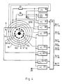
- the outer measuring electrode 13 is divided into more segments, some of them signed by 13/1, 13/j, 13/m and 13/12.
- the number of segments of the outer measuring electrode 13 is not specific, it depends on the given circumstances. An advantageous number is e.g. twelve as depicted in Fig. 4.
- the segments of the outer measuring electrode 13 constitute a segmented ring arranged concentrically to the central electrode 14. Each of the segments is connected to respective units for measuring voltage difference, whereunder only four signed by 22/1, 22/j, 22/m, 22/12 are represented in Fig. 4.
- a common input of the units for measuring voltage difference is connected with the central electrode 14, and thereby the central electrode 14 is linked with the voltmeter 23 having an input driven from the far reference electrode 25 creating the possibility of determining the absolute value of the voltage.
- the Fig. 4 shows only the segments signed by 13/1, 13/j, 13/m, 13/12 connected to the inputs of the units 22/1, 22/j, 22/m, 22/12 for measuring voltage difference, however, obviously all segments of the outer measuring electrode 13 are assigned to respective units for measuring voltage difference, if necessary.
- the outputs of the ammeter 19 and auxiliary ammeter 20, the units 22/1, 22/j, 22/m, 22/12 and the voltmeter 23 are coupled with respective inputs of a second arithmetic data processing unit 26 having outputs 26/1, 26/2, 26/3, 26/4, 26/5, 26/6, 26/7 for forwarding signals according to the measured data.
- the measuring pad 6 of the embodiment represented by the circuit diagram of Fig. 4 is shown front view in Fig. 5 and in cross-section A-A in Fig. 5A.
- the system of the electrodes is arranged on the carrier body 36, on its side facing the wall region 8 to be investigated in the borehole.
- the inner curved surface of the carrier body 36 connected with the arm 7 faces the drilling mud 2.
- the outer curved surface is pressed to the wall region 8 in a way excluding the direct electric contact between the drilling mud 2 and the electrode system.
- the measuring pad 6 is equipped with the point-like central electrode 14 and the further surrounding ring shaped electrodes, i.e.
- the out measuring electrode 13 divided into segments 13/1, 13/i, 13/j, 13/m and 13/12, the first feeding electrode 9, the first and second detecting electrodes 11 and 12 and the second feeding electrode 10.
- the elements for fitting and pressing the measuring pad 6 are not shown in this Figures, too.
- the outer measuring electrode 13 is divided into twelve segments.
- the cross-section is taken along a line A-A crossing the fourth and tenth of the segments, signed by 13/4 and 13/10.
- the arrangement of the further electrodes is the same as shown in the Fig. 2.
- a downhole measuring tool 1 in an embodiment with four measuring pads 6 is shown in cross section in Fig. 6, in a cross section taken along a line VI-VI determined according to Fig. 1.
- the four measuring pads 6/1, 6/2, 6/3, 6/4 are pressed by respective arms 7 to the investigated wall region 8 of the borehole and they bear the electrode systems applied to the measurements (not shown in this Figure).
- the arms 7 bearing the measuring pads 6/1, 6/2, 6/3 and 6/4 are immersed in the drilling mud 2 filling out the interior of the borehole.
- the mechanical construction of the arms 7 ensures that the pads 6/1, 6/2, 6/3, 6/4 are pressed to the wall region 8 mad in the hard rock formation 5 by drilling the borehole in presence of the drilling mud 2.
- the pressing mechanism guarantees that during the measurements there is no direct electric contact between the drilling mud 2 and the electrode system facing the wall region 8 on the measuring pads 6/1, 6/2, 6/3, 6/4.
- the electrode systems of the measuring pads 6/1, 6/2, 6/3 and 6/4 are fed with currents of different frequency values respectively f1, f2, f3 and f4 in order to avoid interference between the measurements carried out simultaneously by the measuring pads 6/1, 6/2, 6/3, 6/4.
- the number of the measuring pads is not limited to four as shown in Fig. 6.
- Advantageously the frequency values are selected in the range to 1 kHz. It should be noted that the mechanical construction of the arms 7 is per se well known and doesn't require more explanation.
- FIG. 7 A further very advantageous embodiment of the apparatus proposed by the present invention is shown in the form of a circuit diagram in Fig. 7.
- This circuit diagram is in most of the details similar to those represented in Figures 2 and 4.
- the measuring pad 6 belonging to a downhole measuring tool 1 (Fig. 1) is intended to determine the geometric orientation of the fractures reaching in a network system the wall region 8 of the borehole and to detect whether a mudcake or a mud layer is present on the wall of the borehole or between the measuring pad 6 and the wall of the borehole.
- the first feeding electrode for supplying the main current signed in the previous Figures by 9 is divided into more, e.g. twelve feeding segments, four of them signed by 9/1, 9/j, 9/o and 9/12.
- the segments of the first feeding electrode 9 are connected over respective first output measuring resistors ⁇ four of them are shown signed by 18/1, 18/j, 18/p, 18/12 ⁇ with an output of the main current generator 15.
- the circuit arrangment is generally the same as shown in Fig. 2.
- the other output of the main current generator 15 is connected with the far return feeding electrode 24, the ring shaped first and second monitoring (detecting) electrodes 11 and 12 for measuring of potential values are connected with respective inputs of the controlled current generator 16 producing the bucking current, coupled through its outputs over the second output measuring resistor 17 to the second feeding electrode 10 and directly to the far return feeding electrode 24.
- the first output measuring electrodes including the resistors signed by 18/1, 18/j, 18/p, 18/12 are connected over their common points with the respective feeding segments, i.e. 9/1, 9/j, 9/p and 9/12 to respective inputs of ammeters, wherein Fig. 8 shows only four ammeters signed by 19/1, 19/j, 19/p, 19/12.
- the poles of the second output measuring resistor 17 are connected to to inputs of the auxiliary ammeter 20 for determining the value of the bucking current.
- the other poles of the first output measuring resistors 18/1, 18/j, 18/p, 18/12 etc. are united by a common conductor led to the respective other inputs of the ammteres 19/1, 19/j, 19/p, 19/12 etc.
- the ring shaped outer measuring electrode 13 and the generally point-like central electrode 14 are coupled with the inputs of the unit 22 for measuring voltage difference.
- the central electrode 14 is connected with the voltmeter 23 for measuring the absolute value of the voltage of the central electrode 14 against the far reference electrode 25.
- the outputs of the ammeters 19/1, 19/j, 19/p, 19/12, auxiliary ammeter 20, unit 22 for measuring voltage difference and voltmeter 23 are coupled with third arithmetic data processing means 27 having outputs 27/1, 27/2, 27/3, 27/4, 27/5, 27/6, 27/7, 27/8 for forwarding respective digital signals according to the measured parameter values.
- Complex arithmetic data processing means are represented in Fig. 8. These means form an expanded version of the third arithmetic data processing means 27.
- the inputs of the complex arithmatic data processing means 28 are generally the outputs 27/1, 27/2, 27/3, 27/4, 27/5, 27/6, 27/7, 27/8 of the third arithmetic data processing means 27 and their outputs signed by 28/1, 28/2, 28/3, 28/4, 28/5, 28/6, 28/7, 28/8, 28/9 are independent on the state of the outputs 27/1, 27/2, 27/3, 27/4, 27/5, 27/6, 27/7 and 27/8 of the third arithmetic data processing means 27.
- the downhole investigating tool 1 illustrated in Fig. 1 is equipped with an inner housing which is electrically isolated from the drilling mud 2.
- This inner housing may include some or nearly all circuit units of the measuring system(s) offered by the invention.
- the arms 7 of the downgole investigasting tool 1 press the insulating carrier bodies 36 of the measuring pads 6 (signed also by 6/1, 6/2, 6/3 and 6/4) to the investigated wall region 8 of the borehole lowered in the hardrock formation 5.
- the measuring pads 6 bear the metallic electrodes which are necessary for generating the microelectric fields of the determination, for monitoring and detecting the generated electric fields, for regulating and measuring some parameters.
- the measuring pads 6 of the downhole investigating tool 1 are made of an insulating material, whereby the metallic electrodes are isolated each from other and the direct galvanic contact with the electrically conducting drilling mud is excluded.
- the metallic electrodes are contacted with the investigated wall region 8 of the hard rock formation 5 through a thin mud layer and if necessary this thin mud layer gives contact to the drilling mud 2.
- the measurements are carried out by the downhole measuring tool 1 suspended in the borehole and forwarded therein in a substantially continuous movement.
- the well logging cable 3 contacts the downhole measuring tool 1 with an appropriate voltage supply unit (not shown in Figures), if necessary and it forms the way of forwarding the signals representing the measured values, the processed measurement data.
- the feeding electrodes 9 and 10 generate at each measuring pad 6 microelectric fields automatically and continuously focused and controlled.
- the continuous generations of the microelectric field renders it possible to carry out the continous measurements relating to the fractures in the investigated wall region 8.
- the basis of processing the measured data is the sampling, wherein the frequency of sampling is selected to be as high as necessary for ensuring the possibility of producing a complex fracture picture by processing the measured data.
- the method ensures the detection of the fractures in the neighbourhood of the borehole with enhancement the presence of the hydraulically conductive open fractures, forming parts of a network of communicating vessels and with suppression of the data assigned to the closed fractures which are the result of the process of lowering the borehole.
- This method is realised by the apparatus in its embodiment shown in Figures 2, 3 and 3A.
- the main current generator 15 supplies current (of intensity I1) through the first output measuring resistor 18 and the ring shaped first feeding electrode 9, signed previously also by A1, to the space of the measurements.
- the first feeding electrode 9 constitutes together with the first output measuring resistor 18 a series member.
- the current supplied and fed into the hard rock formation comes back to the main current generator 15 over the far return feeding electrode 24 (B).
- the field generated by the current of intensity I1 results in a control potential difference ⁇ U1 measurable between the first and second ring shaped monitoring electrodes 11 and 12 (S1 and S2).
- the measured potential difference ⁇ U1 is given to the control input of the controlled current generator 16 which is a high stability current generator for generating bucking current also with high speed of alteration, if necessary.
- the controlled current generator 16 produces the bucking current I2 and feeds it into the measurement space over the second output measuring resistor 17 and the second feeding electrode 10 connected in series.
- the presence of the bucking current I2 results in a countervoltage ⁇ U2 ruling between the first and second monitoring electrodes 11 and 12, wherein the magnitude of the countervoltage ⁇ U2 is equal to that of the potential difference ⁇ U1 but it is of opposite sign.
- the resulted control potential between the first and second monitoring electrodes 11 and 12 is in this case of near zero value.
- the microelectric field sharply focused for longer time according to the mechanism depicted includes a region of minimal potential level constituting a ring shaped space part within the space limited by the first and second monitoring electrodes 11 and 12. This results in producing a potential barrier by the potential field of the bucking current I2, the potential barrier preventing the flow of the measuring current in lateral directions oblong the surface of the measuring pad 6 through the thin mud layer present between the measuring pad 6 and the wall region 8.
- the bucking current I2 can find the way of flowing through the thin mud layer to the basic mass of the drilling mud 2 characterized by relatively high electric conductivity. It follows that in the case of investigating a tight wall region in the borehole the bucking current is very high in comparison to the main measuring current I1, i.e. the output 21/2 of the first arithmetic data processing means forwards a fracture indicator I1/I2 of very low value, practically being equal to zero.
- This fracture comprises electively rically conductive liquid constituted generally by the drilling mud penetrating the fracture and in this conditions a current transport from the main current I1 can be observed from the first ring shaped feeding electrode 9 to the space of the measurements and the intensity of the current flow is increased in dependency on the hydraulic conductivity of the open fracture, i.e. the ratio I1/I2 indicates that a fracture with increased hydraulic conductivity is present.
- This enhancement of the open fractures is the main object of the dimensionless current ration I1/I2 constituting a fractor indicator not only for open fractures.
- the main ammeter 19 For carrying out the measurements the main ammeter 19 produces a signal with level proportional to the intensity of the main current I1.
- the signal is forwarded to an input of the first arithmetic data processing means 21 from the first output measuring resistor 18.
- the auxiliary ammeter 20 forwards from the second output measuring resistor 17 also to the first arithmetic data processing means 21 a signal with level corresponding to the intensity of the bucking current I2.
- the first arithmetic data processing means 21 generates the ratio I1/I2 and forwards it through the output 21/2 of the first arithmetic data processing means 21.
- the unit 22 for measuring voltage difference determines the potential difference U MK between the ring shaped outer measuring electrode 13 (M) and the point-like central electrode 14 (K) and forwards the corresponding signal to a respective input of the first arithmetic data processing means 21.
- the voltmeter 23 determines the absolute potential (voltage) U K of the central electrode 14 taking as basis the potential level of the far reference electrode 25 applied even for voltage measurements (N). This measured value is also forwarded to the first arithmetic data processing means 21, which computes and generates on the output 21/1 a dimensionless second fracture indicator U MK /U K for differentiating the open fractures from the closed ones.
- the second fracture indicator i.e. the ratio U MK /U K has values remarkably low in the case of closed fractures and relatively high values if the fracture is open.
- the first fracture indicator i.e. to the ratio I1/I2 the second indicator has also values increasing with the hydraulic conductivity (permittivity) of the open fractures.
- the first arithmetic data processing means 21 computes further a normalized fracture indicator H, which is also a dimensionless parameter.
- the corresponding signal is forwarded by the output 21/3 of the first arithmetic data processing means 21.
- the normalized fracture indicator H is a modified product of the first and second fracture indicators and it can be given by the formula wherein A and B are mathematical constants reflecting the given geophysical conditions.
- the modified product determined by the formula is capable of enhancing the open fractures from the background of the fractures and giving a signal level according to the hydraulic conductivity.
- the product has very low value in the case of the closed fractures. This results in a very clear picture of the fractures present in the region of the measurements.
- the normalized fracture indicator H reflects in a very sensitive manner the hydraulic conductivity of the open fractures and forms an adequate basis for analyzing the hydraulic conditions of the open fractures, a better basis than either the first fracture indicator I1/I2 or the second fracture indicator U MK /U K taken separately or together.
- the method and apparatus depicted above has a further unexpected advantage, i.e. the absolute potential value U K measured by the voltmeter 23 and the intensity I1 of the main current measured by the ammeter 23 on the basis of the first output measuring resistor 18 give a resistance value which can be identified as apparent microresistivity R a of the microelectric field generated by the main current.
- the first arithmetic data processing means 21 forwards on the output 21/4 a logarithmic signal according to the formula
- the expression R a WU K /I1 with the constant W depending on the downhole measuring tool 1 is a conventional auxiliary parameter facilitating the investigations by reflecting the material of the hard rock formations and by improving the reliability of correlating the fracture indicators H, I1/I2 and U MK /U K of a given depth with other geophysic parameters determined to the same borehole lowered in the given hard rock formation.
- the outer measuring electrode 13 is segmented.
- the number of the segments can be as high as desired, it depends on the technical conditions.
- the practical results show that the best is to apply from 4 to 24 segments, especially 12 segments - the 12 segment arrangement is shown in Figures 4 and 5.
- the potential difference U MK,i assigned to the i-th segment of the outer measuring electrode 13 is measured by the unit 22/i - the Figure 4 shows only four of the segments signed by 13/1, 13/j, 13/m and 13/12 connected with measuring units 22/1, 22/j, 22/m and 22/12.
- the measuring units 22/i are all contacted with respective inputs of the second arithmetic data processing means 26.
- the second arithmetic data processing means 26 carries out more operations than the first arithmetic data processing means 21, it includes more units, operational elements.
- the second arithmetic data processing means 26 receives signals corresponding to the measured potential differences U MK,i and generates in real time mode the mean value U MK as part of the ratio U MK /U K , wherein U K is the absolute potential of the central measuring electrode 14 related to the far reference electrode 25.
- the second arithmetic data processing means 26 produces the average fracture parameter expressed in the form of the following formula:
- the average fracture parameter defined above as U MK /U K is a very good approximation of the fracture indicator U MK /U K defined above with reference to the embodiment of the apparatus according to the invention shown in Figures 2, 3 and 3A, i.e. the embodiments defined above are capable of ensuring the same parameters.
- the average fracture parameter is forwarded further by the output 26/1 of the second arithmetic data processing means 26.
- the mentioned parameters are computed and forwarded in real time mode, they can be stored and applied for creating a full picture of the borehole environment, if they are assigned to different depth levels in the borehole.
- the second arithmetic data processing means 26 For determining the geometric arrangement of the open fractures the second arithmetic data processing means 26 produces in real time mode and stores the elementary fracture indicators U MK,i /U K forming ratios of the potential differences measured for the i-th segment and of the absolute potential U K measured by the central electrode 14. These elementary fracture indicators are forwarded by the output 26/5.
- the second arithmetic data processing means 26 selects in real time or off-line mode the two maximal values from the measured elementary indicators, if they are not assigned to two adjacent segments. In the example of Figure 4 the segments so selected are 13/j and 13/m.
- the maximal elementary fracture indicators U MK,j /U K and U MK,m /U K are forwarded on the outputs 26/6 and 26/7 of the second arithmetic data processing means 26.
- the selected values are also stored together with data necessary for identifying the place of determining them.
- the series of the elementary fracture indicators U MK,i /U K measured versus depth of the borehole and the selected local maximum value U MK,j /U K and U MK,m /U K form an adequate basis for determining the geometric network of the open fractures reaching the wall of the borehole including the determination of the directions of the fractures - they can stretch along broken and curved lines, exceptionally along straight lines.
- the determination of the geometry of the fracture network is generally carried out in off line mode, after completing the measurements and collecting all necessary data and parameters. This process of determining is a normal object for a computer system.
- FIG. 6 it can be seen, how more measurements can be completed simultaneously oblong the circumference of the borehole.
- the Figure shows a four pad measuring arrangement.
- the focused microelectric field is in this case generated in four different places and the simultaneous measurements must not interfere one with another if the reliability of the measured parameter should be ensured.
- the proposed method of simultaneous measurements is carried out by applying four different frequency values signed by f1, f2, f3 and f4.
- the four frequency values assigned to the four pads arranged at the wall of the borehole should differ one from the other with a frequency distance which is as high as necessary for avoiding the interference.
- the frequency difference f2 - f4 between the neighbouring pads 6/1 and 6/2, f4 - f1 between the adjacent pads 6/2 and 6/3 and f1 - f3 between the neighbouring pads 6/3 and 6/4 can be selected to be relatively big in order to ensure the independency of the microelectric fields generated in a controlled manner for carrying out the measurements. It seems to be an interference problem between the neighbouring pads 6/4 and 6/1 because of applying the adjacent frequency values f2 and f3. Of course, by selecting a relatively big difference between f2 and f3 the problem can be avoided and no interference problem occurs.
- the more pad system applied according to Figure 6 is not specific to the construction of the measuring pads 6. There is no difference, whether the measuring pads 6/1, 6/2, 6/3 and 6/4 are constructed according to Figure 2, 4 or 7, with electrode systems according to Figures 3, 3A, 5, 5A or 7.
- the measured data are processed by the corresponding arithmetic data processing means in real time mode and stored versus depth defined along the axis of the borehole.
- the real time display of the measured data is generally realised only in connection with one of the pads 6, e.g.
- the pad 6/1 capable of determining the fracture indicators (I1/I2)1, and (H)1, (H′)1, further the apparent microresistivity values expressed in logarithmic forms:
- the mentioned values can displayed during the measurements and they illustrate the conditions ruling in the borehole.
- the parameters measured on the different pads in a real time mode are stored and in an off-line arrangement they can be applied for determining the image of the network of the open fractures reaching the circumference of the borehole.
- the measured data can be applied in an an obvious way for displaying the parameters related to only one of the cross-sections of the borehole.
- the determination of the continuous picture of the fracture network can be carried out by applying a specific software forming no part of the present invention.
- the geometry of the open fractures reaching the wall of the borehole is determined by the measurement of current intensities I 1,i (i means an integer from 1 to n) characterizing the segments of the first feeding electrode 9 divided into n segments.
- I 1,i i means an integer from 1 to n
- This embodiment of the proposed method is carried out by the apparatus with circuit diagram shown in Figure 7 having, if necessary an expanded complex arithmetic data processing means 28 according to Figure 8.
- the main difference in comparison with the embodiments previously described lies in the application of the segmented first feeding electrode 9 for supllying in the main current.
- the number of the segments applied is not specific, it depends on the given conditions. According to the practice the most advisable is to divide the first feeding electrode 9 into 4 to 24 segments, preferably into 12 segments as it is shown in Fig. 7.
- the first output measuring resistors 18/i (18/1, 18/j, 18/p, 18/12) are applied.
- One of the poles of the first output measuring resistors 18/i is contacted through a common conductor to the main current generator 15 - this ensures a common potential for each segment 9/i (9/1, 9/j, 9/p, 9/12) of the first feeding electrode (ring A1).
- the ammeters 19/i (19/1, 19/j, 19/p, 19/12 measure the current intensities in the segments of the ring A1 and the segment current intensities I 1,i are forwarded to the required input terminals of the third arithmetic data processing means 27.
- the further input terminals of the third arithmetic data processing means 27 receive the following data: intensity I2 of the bucking current measured through the low resistivity second output measuring resistor 17, the voltage difference U MK measured by the unit 22 between the first and second monitoring electrodes 13 and 14, the absolute potential value U K measured between the central electrode 14 and the far reference electrode 25 by the voltmeter 23.
- the parameters measured and forwarded to respective inputs of the third arithmetic data processing means 27 are in a real time process transformed and the following dimensionless ratios are determined and transmitted through the respective outputs: fracture indicators U MK /U K , I 1,1 /I2, ..., I 1,j /I2, ..., I 1,p /I2, ..., I 1,12 /I2 together with the serial numbers of the segments of the first feeding electrode, the sum of segment current intensities, the modified fracture indicator H ⁇ formed on the basis of the first fracture indicator and the sum mentioned according to the formula which determines the hydraulic conductivity of the fractures, and the logarithmic apparent resistivity expressed by the formula
- the mentioned parameter are measured and computed in a continuous process during lowering the downhole measuring tool 1.
- the first fracture indicator U MK /U K the mentioned sum of the segment current intensities, the modified fracture indicator H ⁇ can be registered also versus depth in selected cross sections of the borehole, wherein the momentary position of the downhole measuring tool 1 is registered, too.
- FIG 8 a very schematic representation of a complex arithmetic data processing means 28 is shown in contact with the outputs 27/1 to 27/8 of the third arithmetic data processing means 27.
- the complex means 28 receives the output signals of the third arithmetic data processing means and forwards on the output 28/1 a signal corresponding to the normalized average value of the segment current intensities according to the formula on the output 28/2 the normalized difference of the segment current intensities from the average value according to the formula for each of the segments, on the outputs 28/3, 28/4, 28/5 and 28/6 those of the mentioned normalized differences (at most four with serial number e.g.
- This output is applied also for forwarding the thickness t m of the rugose mud layer present between the insulating pad 6 and the tight wall of the borehole or of the mudcake present in the borehole.
- the complex arithmetic data processing means 28 operates in off-line mode and include storage means for receiving the data from the outputs. The output data are applied for creating a display about the geometric arrangement of the fractures in the network, the geometric arrangement is determined generally versus depth along the axis of the borehole.
- the modified fracture indicator H e (output 28/7), the thickness t m of the mud layer or mudcake (output 28/8) and the specific characteristic data forwarded by the output 28/9 are generally illustrated in function of the depth, depending on the position of the downhole measuring tool 1.
Landscapes
- Life Sciences & Earth Sciences (AREA)
- Engineering & Computer Science (AREA)
- Environmental & Geological Engineering (AREA)
- Geology (AREA)
- Remote Sensing (AREA)
- Physics & Mathematics (AREA)
- General Life Sciences & Earth Sciences (AREA)
- General Physics & Mathematics (AREA)
- Geophysics (AREA)
- Geophysics And Detection Of Objects (AREA)
Applications Claiming Priority (2)
| Application Number | Priority Date | Filing Date | Title |
|---|---|---|---|
| HU882658A HUT51766A (en) | 1988-05-25 | 1988-05-25 | Method and apparatus for discriminative measuring the hydraulically conductive open cracks and non-conductive closed cracks of hard rocks crossed by bore holes |
| HU265888 | 1989-02-15 |
Publications (2)
| Publication Number | Publication Date |
|---|---|
| EP0343744A2 true EP0343744A2 (de) | 1989-11-29 |
| EP0343744A3 EP0343744A3 (de) | 1991-11-27 |
Family
ID=10960495
Family Applications (1)
| Application Number | Title | Priority Date | Filing Date |
|---|---|---|---|
| EP19890201310 Withdrawn EP0343744A3 (de) | 1988-05-25 | 1989-05-22 | Verfahren und Gerät zum Messen an offenen und geschlossenen Brüchen in einer von einem Loch durchbohrten Hartsteinformation |
Country Status (4)
| Country | Link |
|---|---|
| US (1) | US5049822A (de) |
| EP (1) | EP0343744A3 (de) |
| HU (1) | HUT51766A (de) |
| NO (1) | NO892108L (de) |
Cited By (2)
| Publication number | Priority date | Publication date | Assignee | Title |
|---|---|---|---|---|
| WO2000004405A1 (en) * | 1998-07-15 | 2000-01-27 | Schlumberger Limited | Method and apparatus for imaging earth formation |
| CN113050172A (zh) * | 2021-03-12 | 2021-06-29 | 中国电建集团贵阳勘测设计研究院有限公司 | 一种渣库渗漏通道的电流场测试方法 |
Families Citing this family (9)
| Publication number | Priority date | Publication date | Assignee | Title |
|---|---|---|---|---|
| US20040136267A1 (en) * | 2003-01-10 | 2004-07-15 | Kear George R. | Dual imaging sonde including a rotationally and vertically offset second imaging tool |
| US20060203612A1 (en) * | 2003-01-10 | 2006-09-14 | Schlumberger Technology Corporation | Sonde System Including Rotationally and Vertically Offset Tools |
| US7046010B2 (en) * | 2003-12-22 | 2006-05-16 | Halliburton Energy Services, Inc. | Multi-mode microresistivity tool in boreholes drilled with conductive mud |
| US7109719B2 (en) * | 2004-05-11 | 2006-09-19 | Baker Hughes Incorporated | Method and apparatus for azimuthal resistivity measurements in a borehole |
| US7256582B2 (en) * | 2005-04-20 | 2007-08-14 | Baker Hughes Incorporated | Method and apparatus for improved current focusing in galvanic resistivity measurement tools for wireline and measurement-while-drilling applications |
| CN102071931B (zh) * | 2010-12-29 | 2014-01-15 | 中国石油天然气集团公司 | 八臂全方位三维侧向测井方法及测井仪 |
| US10077644B2 (en) | 2013-03-15 | 2018-09-18 | Chevron U.S.A. Inc. | Method and apparatus for generating high-pressure pulses in a subterranean dielectric medium |
| US9664812B2 (en) * | 2013-04-15 | 2017-05-30 | Weatherford Technology Holdings, Llc | Method and apparatus for detection and quantification of borehole standoff |
| CA2981594C (en) * | 2015-04-03 | 2023-10-17 | Rama Rau YELUNDUR | Apparatus and method of focused in-situ electrical heating of hydrocarbon bearing formations |
Family Cites Families (6)
| Publication number | Priority date | Publication date | Assignee | Title |
|---|---|---|---|---|
| US2880389A (en) * | 1954-09-10 | 1959-03-31 | Schlumberger Well Surv Corp | Electrical resistivity well logging |
| US2961600A (en) * | 1956-10-30 | 1960-11-22 | Schlumberger Well Surv Corp | Electrical well logging apparatus |
| US3798535A (en) * | 1972-04-24 | 1974-03-19 | Schlumberger Technology Corp | Methods and apparatus for investigating earth formations |
| US4282486A (en) * | 1978-12-04 | 1981-08-04 | Dresser Industries, Inc. | Dual focused resistivity logging method and apparatus with dynamic range reduction |
| US4468623A (en) * | 1981-07-30 | 1984-08-28 | Schlumberger Technology Corporation | Method and apparatus using pad carrying electrodes for electrically investigating a borehole |
| US4931736A (en) * | 1987-04-13 | 1990-06-05 | Magyar Allami Eotvos Lorand Geofizikai Intezet | Method of and apparatus for microelectric measuring of inhomogeneities on the walls of boreholes for use in well logging |
-
1988
- 1988-05-25 HU HU882658A patent/HUT51766A/hu unknown
-
1989
- 1989-05-22 EP EP19890201310 patent/EP0343744A3/de not_active Withdrawn
- 1989-05-24 US US07/357,065 patent/US5049822A/en not_active Expired - Fee Related
- 1989-05-25 NO NO89892108A patent/NO892108L/no unknown
Cited By (3)
| Publication number | Priority date | Publication date | Assignee | Title |
|---|---|---|---|---|
| WO2000004405A1 (en) * | 1998-07-15 | 2000-01-27 | Schlumberger Limited | Method and apparatus for imaging earth formation |
| US6191588B1 (en) | 1998-07-15 | 2001-02-20 | Schlumberger Technology Corporation | Methods and apparatus for imaging earth formation with a current source, a current drain, and a matrix of voltage electrodes therebetween |
| CN113050172A (zh) * | 2021-03-12 | 2021-06-29 | 中国电建集团贵阳勘测设计研究院有限公司 | 一种渣库渗漏通道的电流场测试方法 |
Also Published As
| Publication number | Publication date |
|---|---|
| HUT51766A (en) | 1990-05-28 |
| US5049822A (en) | 1991-09-17 |
| NO892108D0 (no) | 1989-05-25 |
| EP0343744A3 (de) | 1991-11-27 |
| NO892108L (no) | 1989-11-27 |
Similar Documents
| Publication | Publication Date | Title |
|---|---|---|
| US3132298A (en) | Methods and apparatus for investigating earth boreholes by means of electrodes constructed to contact the borehole walls | |
| US6191588B1 (en) | Methods and apparatus for imaging earth formation with a current source, a current drain, and a matrix of voltage electrodes therebetween | |
| EP1922570B1 (de) | Hochauflösender erdbildgeber für den spezifischen widerstand | |
| EP0759563B1 (de) | Anordnung und Verfahren zur Widerstandsmessung von unterirdischen Formationen | |
| US6714014B2 (en) | Apparatus and method for wellbore resistivity imaging using capacitive coupling | |
| EP1875274B1 (de) | Verfahren und vorrichtung zur verbesserten stromfokussierung in galvanischen messwerkzeugen für den spezifischen widerstand | |
| CA2529741C (en) | Formation resistivity measurement sensor contained onboard a drill bit (resistivity in bit) | |
| EP1929332B1 (de) | Hochauflösender erd-bildgeber für spezifischen widerstand | |
| EP1913425B1 (de) | Hochauflösender erd-bildgeber für spezifischen widerstand | |
| EP3185047B1 (de) | Hochauflösende spannungsmessanordnung | |
| US7639016B2 (en) | Downhole multi-phase flow imager | |
| US20080303526A1 (en) | Imaging Based on 4-Terminal Dual-Resistor Voltage Measurements | |
| US20100299068A1 (en) | Apparatus for determining the concentration of a conductive fluid present in a fluid filled borehole | |
| US5049822A (en) | Method of and apparatus for carrying out measurements on open and closed fractures in a hard rock formation pierced by a borehole | |
| US7612567B2 (en) | Two-axial pad formation resistivity imager | |
| EP0013068A1 (de) | Verfahren zum Entdecken von Kohlenwasserstoffen zur indirekten Detektion von Kohlenwasserstoffreservoirs | |
| US6636046B2 (en) | Electrical resistivity probes | |
| EP1920272B1 (de) | Verfahren und vorrichtung zur verbesserung von mit bohrloch-galvanikwerkzeugen erhaltenen bildern des spezifischen formationswiderstands | |
| WO2008033885A2 (en) | Method and apparatus for resistivity imaging in boreholes filled with low conductivity fluids | |
| US5191290A (en) | Logging apparatus for measurement of earth formation resistivity | |
| CN101432742A (zh) | 两轴垫状物地层电阻率成像仪 | |
| US4931736A (en) | Method of and apparatus for microelectric measuring of inhomogeneities on the walls of boreholes for use in well logging | |
| CA1051518A (en) | Well logging methods and apparatus | |
| US3601692A (en) | Electrical logging system utilizing impedance means between survey and measure electrodes | |
| US2872637A (en) | Electrical resistivity well logging methods and apparatus |
Legal Events
| Date | Code | Title | Description |
|---|---|---|---|
| PUAI | Public reference made under article 153(3) epc to a published international application that has entered the european phase |
Free format text: ORIGINAL CODE: 0009012 |
|
| AK | Designated contracting states |
Kind code of ref document: A2 Designated state(s): DE FR GB IT NL |
|
| PUAL | Search report despatched |
Free format text: ORIGINAL CODE: 0009013 |
|
| AK | Designated contracting states |
Kind code of ref document: A3 Designated state(s): DE FR GB IT NL |
|
| STAA | Information on the status of an ep patent application or granted ep patent |
Free format text: STATUS: THE APPLICATION IS DEEMED TO BE WITHDRAWN |
|
| 18D | Application deemed to be withdrawn |
Effective date: 19920528 |