EP0343665A2 - Variable optical axis type bottle inspecting apparatus - Google Patents
Variable optical axis type bottle inspecting apparatus Download PDFInfo
- Publication number
- EP0343665A2 EP0343665A2 EP89109451A EP89109451A EP0343665A2 EP 0343665 A2 EP0343665 A2 EP 0343665A2 EP 89109451 A EP89109451 A EP 89109451A EP 89109451 A EP89109451 A EP 89109451A EP 0343665 A2 EP0343665 A2 EP 0343665A2
- Authority
- EP
- European Patent Office
- Prior art keywords
- bottle
- optical axis
- lens
- changing
- signal
- Prior art date
- Legal status (The legal status is an assumption and is not a legal conclusion. Google has not performed a legal analysis and makes no representation as to the accuracy of the status listed.)
- Ceased
Links
Images


Classifications
-
- G—PHYSICS
- G01—MEASURING; TESTING
- G01N—INVESTIGATING OR ANALYSING MATERIALS BY DETERMINING THEIR CHEMICAL OR PHYSICAL PROPERTIES
- G01N21/00—Investigating or analysing materials by the use of optical means, i.e. using sub-millimetre waves, infrared, visible or ultraviolet light
- G01N21/84—Systems specially adapted for particular applications
- G01N21/88—Investigating the presence of flaws or contamination
- G01N21/90—Investigating the presence of flaws or contamination in a container or its contents
-
- G—PHYSICS
- G01—MEASURING; TESTING
- G01N—INVESTIGATING OR ANALYSING MATERIALS BY DETERMINING THEIR CHEMICAL OR PHYSICAL PROPERTIES
- G01N21/00—Investigating or analysing materials by the use of optical means, i.e. using sub-millimetre waves, infrared, visible or ultraviolet light
- G01N21/84—Systems specially adapted for particular applications
- G01N21/88—Investigating the presence of flaws or contamination
- G01N21/8806—Specially adapted optical and illumination features
- G01N2021/8829—Shadow projection or structured background, e.g. for deflectometry
- G01N2021/8832—Structured background, e.g. for transparent objects
Definitions
- An object of this invention is to provide a compact bottle inspecting apparatus with the optical path not bent, which is capable of following a bottle on continuous move.
- variable optical axis type bottle inspecting apparatus the optical axis of an optical system is varied relatively to photoelectric means, whereby images of lights transmitted through a bottle on continuous move are formed consecutively on photoelectric means. This makes it possible that a bottle on continuous move is followed with the optical path not bent orthogonal. Consequently the apparatus can be miniaturized as a whole.
- Fig. 1 shows the variable optical axis type bottle inspecting apparatus according to one embodiment of this invention.
- a bottle 12 to be inspected by the apparatus according to this invention is conveyed continuously while being rotated.
- the bottle 12 is illuminated by a diffused light source 10 with a surface for emitting uniform diffused lights.
- An image of lights transmitted through the sidewall of the bottle 12 (a transmitted light image) is formed on a one-dimensional photoelectric device 16 by way of an optical axis changing unit 14.
- the one-dimensional photoelectric device 16 comprises a photo detecting unit for converting a transmitted light image to an electric analog signal as a linear CCD does, and an optical system for forming a transmitted light image of the sidewall of a bottle.
- the one-dimensional photoelectric device 16 and the optical axis changing unit 14 are shown in more detail in Fig. 2.
- Fig. 2(a) is a side view
- Fig. 2(b) is a front view.
- the optical system for forming a transmitted light image of the bottle 12 comprises a combination lens 16a provided on the forward end of the one-dimensional photoelectric device 16, and a concave lens 14a in the optical axis changing unit 14.
- the optical axis changing unit 14 swings the concave lens 14a so as to change the optical axis.
- a lens support member 14b has one end supporting the concave lens 14a and the other end connected to a support member 14d swingably on a pin 14c.
- the support member 14d is fixed to the front of the one-dimensional photoelectric device 16.
- An A/D converter 18 converts an analog image signal from the one-dimensional photoelectric converter 16 into a digital image signal of a given bit number.
- the digital image signal is supplied to an inspection area gate setting circuit 20, a monitor display RAM circuit 22 and a defect detection circuit 24.
- a judge circuit 28 judges whether or not a defect is present, based on defect signals which have been masking. For example, a number of the defect signals are counted for each scan, and when the counted value exceeds a set value, the scan is judged an error scan (a defect scan line). The judge circuit 28 further counts a number of continuous error scans, and when the counter value exceed a set value, the bottle 12 is judged a defective bottle. A resultant judge signal is outputted to a conveying line (not shown), and in accordance with the judge signal, the conveying system ejects the defective bottle.
- the inspection period signal is set so as to allow the bottle 12 to make one rotation over the distance 1 while the concave lens 14a is following the bottle 12 over the distance M. That is, the inspection period signal becomes high level during a period corresponding to Lx0.85 (>1).
- the reference signal generator 30 uses a ROM for generating the lens swing angle signal, the inspection period signal and the RAM write signal. That is, a lens swing angle signal, an inspection period signal and a RAM signal are written beforehand in the ROM at an address of a bottle position signal. A bottle position signal is inputted as an address, and then a lens swing angle signal, an inspection period signal and a RAM write signal are supplied.
- the lens and the one-dimensional photoelectric converter are arranged linearly to constitute the optical system.
- This allows the optical system to be adjacently arranged in a plural number.
- four optical systems respectively comprising concave lenses 141, 142, 143, 144, and one-dimensional photoelectric apparatus 161, 162, 163, 164 are arranged to enable the bottle 12 conveyed at such a high speed to be inspected for defects.
- the one-dimensional photoelectric device is used for the detection of a transmitted light image of the bottle 12, but a two-dimensional photoelectric device, such as an area CCD, may be used.
- the optical axis changing unit changes the optical axis, so that the bottle 12 continuously conveyed is followed, and the two-dimensional photoelectric device converts a transmitted light image at a preset timing.
- the use of the two-dimensional photoelectric device allows images of transmitted lights through one bottle at a plural positions thereof while the bottle is continuously conveyed. The inspection result becomes accordingly precise.
- the defect detecting system used in this apparatus is not limited to the system described in the embodiment and may cover various modifications. To give examples, it is possible that when the following formulae QA / QB ⁇ (constant C) QA / QB ⁇ 1/(constant C) where brightnesses to be computed for comparison are denoted by QA and QB are satisfied, a defect is present.
Landscapes
- Physics & Mathematics (AREA)
- Health & Medical Sciences (AREA)
- Life Sciences & Earth Sciences (AREA)
- Chemical & Material Sciences (AREA)
- Analytical Chemistry (AREA)
- Biochemistry (AREA)
- General Health & Medical Sciences (AREA)
- General Physics & Mathematics (AREA)
- Immunology (AREA)
- Pathology (AREA)
- Investigating Materials By The Use Of Optical Means Adapted For Particular Applications (AREA)
- Length Measuring Devices By Optical Means (AREA)
Abstract
A variable optical axis type bottle inspecting apparatus is disclosed. The bottle inspecting apparatus comprises illuminating means (10) for illuminating a bottle (12) continuously conveyed on rotation, an optical system for forming an image of lights transmitted through the bottle, photoelectric converting means for photoelectrically converting the transmitted light image of the bottle, optical axis changing means (14) for changing the optical axis of the optical system with respect to the photoelectric converting means (16) so that the transmitted light image of the bottle continuously conveyed is formed consecutively on the photoelectric converting means, and inspecting means for inspecting the sidewall of the bottle for defects, based on the transmitted light images photoelectrically converted by the photoelectric converting means. In the variable optical axis type bottle inspecting apparatus, the optical axis of an optical system is varied relatively to photoelectric means, whereby images of lights transmitted through a bottle on continuous move are formed consecutively on photoelectric means (16). This makes it possible that a bottle on continuous move is followed with the optical path not bent orthogonal. Consequently the apparatus can be miniaturized as a whole.
Description
- This invention relates to a variable optical axis type bottle inspecting apparatus for detecting defects on a bottle on rotation.
- Glass bottles containing liquors, beverages, foods, etc. have to be inspected for any defect whether the bottles are newly made or have been recovered for reuses. The bottles are inspected on portions, i.e., the body or sidewall, bottom, top of the mouth, and threaded bottle neck. A bottle being inspected is conveyed continuously at a high speed while being rotated. Conventionally a mirror is inserted in an optical path and is moved so as to enable a camera to follow the bottle on continuous move.
- But a problem with the bottle inspecting apparatus including the mirror is that the optical path is bent substantially orthogonal, which makes the apparatus large-sized.
- An object of this invention is to provide a compact bottle inspecting apparatus with the optical path not bent, which is capable of following a bottle on continuous move.
- This object is achieved by a variable optical axis type bottle inspecting apparatus comprising: illuminating means for illuminating a bottle continuously conveyed on rotation; an optical system for forming an image of lights transmitted through the bottle; photoelectric converting means for photoelectrically converting the transmitted light image of the bottle; optical axis changing means for changing the optical axis of the optical system with respect to the photoelectric converting means so that the transmitted light image of the bottle continuously conveyed is formed consecutively on the photoelectric converting means; and inspecting means for inspecting the sidewall of the bottle for defects, based on the transmitting light images photoelectrically converted by the photoelectric converting means.
- In the variable optical axis type bottle inspecting apparatus according to this invention, the optical axis of an optical system is varied relatively to photoelectric means, whereby images of lights transmitted through a bottle on continuous move are formed consecutively on photoelectric means. This makes it possible that a bottle on continuous move is followed with the optical path not bent orthogonal. Consequently the apparatus can be miniaturized as a whole.
-
- Fig. 1 is a block diagram of the variable optical axis type bottle inspecting apparatus according to one embodiment of this invention;
- Figs. 2 and 3 are views of optical systems used in the variable optical axis type bottle inspecting apparatus of Fig. 1
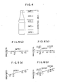
- Fig. 4 is a view showing inspection areas and inspection gates of the variable optical axis type bottle inspecting apparatus of Fig. 1;
- Figs. 5 and 6 are explanatory views of defect detecting systems of the variable optical axis type bottle inspecting apparatus of Fig. 1;
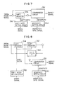
- Fig. 7 is a block diagram of an example of the defect detecting circuit for conducting the defect detecting system of Fig. 5;
- Fig. 8 is a block diagram of an example of the defect detecting circuit for conducting the defect detecting system of Fig. 6;
- Figs. 9 and 10 are views explaining the relationships of a bottle position with a lens swing angle signal, an inspection period signal and a RAM write signal for the variable optical axis type detecting apparatus of Fig. 1;
- Fig. 11 is a view of another embodiment of the variable optical axis type bottle inspecting apparatus; and
- Fig. 12 is a view of further another embodiment of the variable optical axis type defect inspecting apparatus.
- Fig. 1 shows the variable optical axis type bottle inspecting apparatus according to one embodiment of this invention. A
bottle 12 to be inspected by the apparatus according to this invention is conveyed continuously while being rotated. Thebottle 12 is illuminated by a diffusedlight source 10 with a surface for emitting uniform diffused lights. An image of lights transmitted through the sidewall of the bottle 12 (a transmitted light image) is formed on a one-dimensionalphotoelectric device 16 by way of an opticalaxis changing unit 14. The one-dimensionalphotoelectric device 16 comprises a photo detecting unit for converting a transmitted light image to an electric analog signal as a linear CCD does, and an optical system for forming a transmitted light image of the sidewall of a bottle. - The optical
axis changing unit 14 is disposed on the side of the optical system of the one-dimensionalphotoelectric device 16 opposed to thebottle 12 and changes the optical axis of the optical system relative to the photo detecting unit of the one-dimensionalphotoelectric device 16. The opticalaxis changing unit 14 changes the optical axis synchronously with movement of thebottle 12 so that a transmitted light image may be formed on the photo detecting unit of the one-dimensionalphotoelectric device 16. That is, for a change of the optical axis, alens 14a provided on the front of the one-dimensionalphotoelectric device 16 is driven by amotor 15 driven by a lens driving circuit 21. - The one-dimensional
photoelectric device 16 and the opticalaxis changing unit 14 are shown in more detail in Fig. 2. Fig. 2(a) is a side view, and Fig. 2(b) is a front view. The optical system for forming a transmitted light image of thebottle 12 comprises acombination lens 16a provided on the forward end of the one-dimensionalphotoelectric device 16, and aconcave lens 14a in the opticalaxis changing unit 14. The opticalaxis changing unit 14 swings theconcave lens 14a so as to change the optical axis. Alens support member 14b has one end supporting theconcave lens 14a and the other end connected to asupport member 14d swingably on apin 14c. Thesupport member 14d is fixed to the front of the one-dimensionalphotoelectric device 16. Thedrive shaft 15a of themotor 15, and the forward end of thelens support member 14b are interconnected by an arm 14e so that, as shown in Fig. 2(b), theconcave lens 14a is swung right and left through the arm 14e in accordance with clockwise and counter-clockwise rotation of themotor shaft 15a by a certain angle. - The principle of following the
bottle 12 continuously moving on rotation will be explained with reference to Fig. 3. The opticalaxis changing unit 14 changes the optical axis of the optical system with respect to thelinear CCD 16b, and with respect to thebottle 12 on continuous move the opticalaxis changing unit 14 changes theoptical axis 14x of theconcave lens 14a as shown in Fig. 3. That is, as thebottle 12 is conveyed from a position A to a position A′, theconcave lens 14 is moved from the position A′ to the position A in the opposite direction of conveyance of thebottle 12, so that theoptical axis 14x is changed from the position A to the position A′. This arrangement permits the center of a transmitted light image of thebottle 12 to be formed constantly at a given position of thelinear CCD 16b. Thebottle 12 is caused to make one rotation during the conveyance from the position A to the position A′. Resultantly an image of the entire circumference of thebottle 12 can be inputted by means of the linear CCD. - An A/
D converter 18 converts an analog image signal from the one-dimensionalphotoelectric converter 16 into a digital image signal of a given bit number. The digital image signal is supplied to an inspection areagate setting circuit 20, a monitordisplay RAM circuit 22 and adefect detection circuit 24. - As shown in Fig. 4, the inspection area
gate setting circuit 20 determines vertically sectioned inspection areas of a transmitted light image where thedefect detection circuit 24 detects defects based on the transmitted light image which will be explained below. The inspection areas may be determined based on the upper and the lower end edges of thebottle 12 depending on a shape of thebottle 12, or may be fixed. In Fig. 4, the inspection area is set on the entire bottle, and the inspection area is divided intoinspection gates bottle 12. The inspection areagate setting circuit 20 supplies an inspection gate signal indicative of an inspection gate of the inspection area in which is a current scan position of thelinear CCD 16b to the monitordisplay RAM circuit 22, thedefect detection circuit 24, amasking circuit 26, and ajudge circuit 28. - Based on a digital image signal from the A/
D converter 18, thedefect detection circuit 24 compares in brightness a plurality of points spaced vertically and horizontally from each other by a given distance so as to detect defects. - The defect detecting method includes a two-point defect detecting system, in which brightness is compared between two points, and a three-point defect detecting system in which brightness is compared among three points. Fig. 5 explains the two-point defect detecting system, and Fig. 6 explains the three-point defect detecting system.
- In the two-point defect detecting system, when the following formula
| QA - QB | ≧ (constant A)
in which brightnesses at two points A and B are represented by QA and QB respectively is satisfied, there are defects. - In the case of Fig. 5, defects can be detected by the following formula
| QA1 - QB1 | ≧ (constant A)
| QA2 - QB2 | ≧ (constant A)
in which brightnesses are points A1 and B1, and A2 and B2 on one scanning line are represented respectively by QA1, QB1, QA2, QB2. A constant A is preset in accordance with types, etc. of thebottle 12. As shown in Fig. 5(a), when a transmitted light image has even brightness along a scanning line,
QA1 - QB1 > A
QA2 - QB2 = 0
are satisfied, and it is found that the point B1 is a defect. This two-point defect detecting system is effective for the case of even brightness. In the case of uneven brightness along a scanning line as shown in Fig. 5(b), the following formulas
| QA1 - QB1 | < A
| QA2 - QB2 | < A
are given. There is a risk that the defect at the point B1 will be missed. - But the three-point defect detecting system enables defects to be detected without failure even in the case of uneven brightness along a scanning line as shown in Fig. 5(b). In the three-point defect detecting system, the following formula
| QB - {( QA + QC )/2 } | ≧ (constant B)
in which brightnesses at three points A, B, and C are represented by QA, QB and QC is used to detect defects. A constant B is preset in accordance with types, etc. of thebottle 12. - In the case of Fig. 6, defect are detected using the following formulas
| QB1 - {(QA1 + QC1)/2 } | ≧ (constant B)
| QB2 - {(QA2 + QC2)/2 } | ≧ (constant B)
in which brightnesses at points A1, B1, C1 on a scanning line of the area CCD 16d are represented by QA1, QB1, QC1, QA2, QB2, QC2. The brightnesses compared with those at intermediate points B1 and B2 are an arithmetic average of the brightnesses of points A1 and C1 on both sides of the intermediate point B1 and that of the brightnesses of points A2 and C2 on both sides of the intermediate point B2, respectively. The three-point defect detecting system enables the defect B1 to be detected correctly both in the case of even brightness as in Fig. 6(a) and in the case of uneven brightness as in Fig. 6(b). - Fig. 7 shows an example of the
defect detection circuit 24 for the two-point defect detecting system. A distance between two points is determined by a shift width of ashift register 24a to which is sequentially inputted a digital image signal. The shift width is determined by a shiftwidth setting unit 24b. Acomparator 24c compares a currently inputted digital image signal with an output signal of theshift register 24a which is a preceding signal by a shift width so as to judge whether or not the absolute valve of a difference between the two is larger than a sensitivity (i.e., a constant A) set by thesensitivity setting unit 24d. The constant A varies for the inspection gates. Thesensitivity setting unit 24d outputs a suitable constant A based on an input inspection gate signal to thecomparator 24c. - Fig. 8 shows an example of the
defect detection circuit 24 of the three-point defect detecting system. The distance between one of the three points and an adjacent one is determined by shift widths of ashift registers shift registers computing circuit 24h computes an arithmetic average of a current input digital image signal and a digital image signal outputted from theshift register 24f. Acomparator 24i compares an average brightness computed by thecomputing circuit 24h with a digital image signal from theshift register 24e to judge whether or not the absolute value of a difference between the two is larger than a sensitivity (i.e., a constant B) set by asensitivity setting unit 24j to output a defect signal. The constant B varies for the inspection gates. Thesensitivity setting unit 24j outputs to thecomparator 24i a suitable constant B based on an input inspection gate signal. - In the defect detecting circuits of Figs. 7 and 8 in which two points or three points on a scanning line of the
linear CCD 16b (i.e., vertically of the bottle 12) are compared in brightness, when two or three points located horizontally of thebottle 12 are compared in brightness, digital image signals are stored in a memory (not shown) for a number of necessary scanning lines, and the digital image signals are sequentially read from the memory vertically of the scanning lines to input the read digital image signals in ashift register shift register bottle 12, and thus a spinning speed signal is supplied to ashift width circuit 24b or 24g which sets shift widths. Consequently, even when the spinning speed varies, two or three points spaced from one another by a substantially constant distance can be compared. - A defect signal outputted from the
defect detection circuit 24 is masked by a maskingcircuit 26. When the sensitivity of thedefect detection circuit 24 is increased to avoid errors in the defect detection, a part which is not a defect is falsely detected as a defect. The masking is for removing such false defect signal. At a real defect, defect signals are continuously generated in accordance with a size of the defect, and at the remaining normal part, defect signals are separately generated. The masking eliminates as a false defect signal an isolated defect signal and defect signals continuing only below a set value. - A
judge circuit 28 judges whether or not a defect is present, based on defect signals which have been masking. For example, a number of the defect signals are counted for each scan, and when the counted value exceeds a set value, the scan is judged an error scan (a defect scan line). Thejudge circuit 28 further counts a number of continuous error scans, and when the counter value exceed a set value, thebottle 12 is judged a defective bottle. A resultant judge signal is outputted to a conveying line (not shown), and in accordance with the judge signal, the conveying system ejects the defective bottle. - A
reference signal generator 30 generates and outputs a lens swing angle signal, an inspection period signal and a RAM write signal, based on a bottle position signal from abottle position detector 32. The lens swing angle signal is for swinging theconcave lens 14a so that an image on the center line of thebottle 12 is formed constantly on the one-dimensionalphotoelectric device 16 and is supplied to the lens driving circuit 21. The lens driving circuit 21 swings theconcave lens 14a based on the lens swing angle signal. The inspection period signal is for indicating an inspection period in which theconcave lens 14a moves following thebottle 12 on continuous move and is supplied to thejudge circuit 28. The RAM write signal is for indicating a timing for a digital image signal to be written in the monitordisplay RAM unit 22. Amonitor 36 displays a digital image signal of 480 scans at an equal pitch, in an inspection period indicated by the inspection signal. - Figs. 9 and 10 show the relationships among the lens swing angle, the inspection period signal, and the RAM write signal. As shown in Fig. 9, a pitch for the
bottle 12 to be continuously conveyed at is represented by L; a distance for the bottle to travel over during one rotation, 1 ( = L x 0.8 ); and a distance for theconcave lens 14a to follow thebottle 12 over, M ( = L x 0.9 ). - The lens swing angle is so changed that the
concave lens 14a is swung in the direction opposite to the conveyance of thebottle 12 while thebottle 12 is between the points A and A′ (Fig. 10(a)) and is so changed that theconcave lens 14a is returned to the position A′ as soon as thebottle 12 reaches the position A′. At this time anext bottle 12 is at a position B, and the lens swing angle signal is not changed until thenext bottle 12 reaches the point A. When thenext bottle 12 reaches the position A, the lens swing angle signal is so changed that theconcave lens 14a follow thenext bottle 12. - The inspection period signal is set so as to allow the
bottle 12 to make one rotation over thedistance 1 while theconcave lens 14a is following thebottle 12 over the distance M. That is, the inspection period signal becomes high level during a period corresponding to Lx0.85 (>1). - The RAM write signal is of pulses corresponding to a number of scanning lines necessary to scan the entire circumference of the
bottle 12. For example, when a pulse signal corresponding to 480 scanning lines for scanning the entire circumference of thebottle 12 is written in the monitordisplay RAM unit 22, as shown in Fig. 9(d), a RAM write signal of 480 pulses is outputted at the high level of an inspection period signal. - The
reference signal generator 30 uses a ROM for generating the lens swing angle signal, the inspection period signal and the RAM write signal. That is, a lens swing angle signal, an inspection period signal and a RAM signal are written beforehand in the ROM at an address of a bottle position signal. A bottle position signal is inputted as an address, and then a lens swing angle signal, an inspection period signal and a RAM write signal are supplied. - Based on a lens swing angle signal from the
reference signal generator 30, the lens driving circuit 21 drives theconcave lens 14a. The lens driving circuit 21 performs the feedback control using the lens swing angle signal as a feedback signal. Unless theconcave lens 14a outputs a lens swing angle signal, the lens driving circuit 21 controls in the open-loop. - An inspection period signal from the
reference signal generator 30 is supplied to thejudge circuit 28. Thejudge circuit 28 judges whether or not thebottle 12 is defective by taking as effective the defect signals supplied thereto in a period when the inspection period signal is of high level. Otherwise it is possible to output an inspection period signal from thereference signal generator 30 to the inspection areagate setting circuit 20, thedefect detection circuit 24, or the maskingcircuit 26 to take as effective only the defect detecting signals supplied in a period when the inspection period signal is of high level. - A RAM write signal from the
reference signal generator 30 is outputted to the monitordisplay RAM circuit 22. Based on this RAM write signal, a digital image signal the A/D converter 18 is written in the monitordisplay RAM circuit 22. The monitordisplay RAM circuit 22 has been supplied, in addition to the RAM write signal, with a defect detecting signal from the maskingcircuit 26, an erroneous scan signal and a judge result signal from thejudge circuit 28, and an inspection gate signal from the inspection areagate setting circuit 20. Based on the defect signal and the erroneous scan signal, defects and erroneous scans are written in the monitordisplay RAM circuit 22. Based on the inspection gate signal, an inspection gate is displayed on themonitor 36. - The monitor
display RAM circuit 22 has two frame memories and alternately uses the two frame memories to store a digital image signal of thebottle 12 being inspected, and that of an immediately preceding inspectedbottle 12. Normally the digital image signal of thebottle 12 being inspected is displayed continuously on themonitor 36, but when a judge signal indicative of a defective bottle is inputted from thejudge circuit 28, the content of the digital image signal of the defective bottle stored in the frame memory is displayed on themonitor 36 for detailed inspection of the defective condition. - As described above, the apparatus according to this embodiment, which is compact, makes it possible to locate defects on the sidewall of a bottle continuously conveyed on rotation and inspect the same.
- This invention is not limited to the above-described embodiment and cover various modifications.
- In the embodiment, as shown in Fig. 2, the
concave lens 14a is provided on the front of the one-dimensionalphotoelectric device 16 and swung, but in place of the concave lens, a convex lens may be used and swung. - As shown in Fig. 11, the
concave lens 14a may be driven linearly by linear drive means 15′ so as to change the optical axis. - According to this invention, the lens and the one-dimensional photoelectric converter are arranged linearly to constitute the optical system. This allows the optical system to be adjacently arranged in a plural number. Even in the case the
bottle 12 is conveyed continuously at such a high speed that it is impossible to inspect the bottle for defects by means of one optical system, as shown in Fig. 12, four optical systems respectively comprisingconcave lenses photoelectric apparatus bottle 12 conveyed at such a high speed to be inspected for defects. - In the embodiment, the one-dimensional photoelectric device is used for the detection of a transmitted light image of the
bottle 12, but a two-dimensional photoelectric device, such as an area CCD, may be used. In the case of using the two-dimensional photoelectric device, the optical axis changing unit changes the optical axis, so that thebottle 12 continuously conveyed is followed, and the two-dimensional photoelectric device converts a transmitted light image at a preset timing. The use of the two-dimensional photoelectric device allows images of transmitted lights through one bottle at a plural positions thereof while the bottle is continuously conveyed. The inspection result becomes accordingly precise. - The defect detecting system used in this apparatus is not limited to the system described in the embodiment and may cover various modifications. To give examples, it is possible that when the following formulae
QA / QB ≧ (constant C)
QA / QB ≧ 1/(constant C)
where brightnesses to be computed for comparison are denoted by QA and QB are satisfied, a defect is present. It is also possible that when the following formulae
QB / {( QA + QC )/2 } ≧ (constant D)
QB / {( QA + QC)/2 } ≧ 1/(constant D)
where brightnesses at three points to be compared are represented by QA, QB and QC, and constants C and D arenumbers 1 or more, a defect is present. - This invention can be applicable to any part other than the sidewall of a bottle. The principle of this invention is applicable to the inspection of objects other than bottles.
Claims (6)
1. A variable optical axis type bottle inspecting apparatus comprising:
illuminating means (10) for illuminating a bottle continuously conveyed on rotation;
an optical system (14a, 16a) for forming an image of lights transmitted through the bottle;
photoelectric converting means (16) for photoelectrically converting the transmitted light image of the bottle;
optical axis changing means (14) for changing the optical axis of the optical system with respect to the photoelectric converting means so that the transmitted light image of the bottle continuously conveyed is formed consecutively on the photoelectric converting means; and
inspecting means (24, 26, 28) for inspecting the widewall of the bottle for defects, based on the transmitted light images photoelectrically converted by the photoelectric converting means.
2. A variable optical axis type bottle inspecting apparatus according to claim 1, wherein
the optical system (14a, 16a) has a lens (14a) for changing the optical axis of the optical system inserted in an optical path interconnecting the photoelectric converting means and the bottle; and
the optical axis changing means (14) moves the lens for changing the optical axis in synchronization with the movement of the bottle.
3. A variable optical axis type bottle inspecting apparatus according to claim 2, wherein the optical axis changing means (14) has swing means (15) for swinging the lens for changing the optical axis in synchronization with the movement of the bottle.
4. A variable optical axis type bottle inspecting apparatus according to claim 3, wherein the optical axis changing means (14) has linear driving means (15′) for swinging the lens for changing the optical axis, in synchronization with the movement of the bottle.
5. A variable optical axis type defect inspecting apparatus according to any one of claims 2 - 4, wherein the lens (14a) for changing the optical axis comprises a convex lens.
6. A variable optical axis type defect inspecting apparatus according to any one of claims 2 - 4, wherein the lens (14a) for changing the optical axis comprises a concave lens.
Applications Claiming Priority (2)
| Application Number | Priority Date | Filing Date | Title |
|---|---|---|---|
| JP63128246A JPH01299443A (en) | 1988-05-27 | 1988-05-27 | Optical axis shifting type inspecting apparatus for bottle |
| JP128246/88 | 1988-05-27 |
Publications (2)
| Publication Number | Publication Date |
|---|---|
| EP0343665A2 true EP0343665A2 (en) | 1989-11-29 |
| EP0343665A3 EP0343665A3 (en) | 1990-08-16 |
Family
ID=14980110
Family Applications (1)
| Application Number | Title | Priority Date | Filing Date |
|---|---|---|---|
| EP89109451A Ceased EP0343665A3 (en) | 1988-05-27 | 1989-05-25 | Variable optical axis type bottle inspecting apparatus |
Country Status (3)
| Country | Link |
|---|---|
| US (1) | US4983822A (en) |
| EP (1) | EP0343665A3 (en) |
| JP (1) | JPH01299443A (en) |
Cited By (1)
| Publication number | Priority date | Publication date | Assignee | Title |
|---|---|---|---|---|
| US7060999B2 (en) | 2004-07-09 | 2006-06-13 | Owens-Brockway Glass Container Inc. | Apparatus and method for inspecting ribbed containers |
Families Citing this family (8)
| Publication number | Priority date | Publication date | Assignee | Title |
|---|---|---|---|---|
| US5466927A (en) * | 1994-04-08 | 1995-11-14 | Owens-Brockway Glass Container Inc. | Inspection of translucent containers |
| DE19741384A1 (en) * | 1997-09-19 | 1999-03-25 | Heuft Systemtechnik Gmbh | Method for recognizing random dispersive material, impurities and other faults in transparent objects |
| US6393141B1 (en) * | 1998-09-10 | 2002-05-21 | Warner-Lambert Company | Apparatus for surface image sensing and surface inspection of three-dimensional structures |
| US6304323B1 (en) * | 1998-11-30 | 2001-10-16 | Kirin Techno-System Corporation | Method for detecting defect in bottle |
| JP4346968B2 (en) * | 2003-06-13 | 2009-10-21 | キヤノン株式会社 | Radiation imaging method, radiation imaging apparatus, and computer program |
| US7148961B1 (en) | 2004-11-10 | 2006-12-12 | Owens-Brockway Glass Container Inc. | Container sidewall inspection |
| DE102005017957A1 (en) * | 2005-04-18 | 2006-10-26 | Khs Ag | inspection device |
| JP6108068B2 (en) * | 2012-11-13 | 2017-04-05 | 東洋製罐株式会社 | Can body inspection apparatus and method |
Family Cites Families (9)
| Publication number | Priority date | Publication date | Assignee | Title |
|---|---|---|---|---|
| US3378687A (en) * | 1963-06-25 | 1968-04-16 | Trw Inc | Scanning system which optically locks on object and mechanically scans surrounding field |
| US3411009A (en) * | 1964-10-05 | 1968-11-12 | Fords Fensbury Ltd | Radiation sensitive apparatus for detecting dirt in transparent bottles |
| US3797632A (en) * | 1971-12-17 | 1974-03-19 | Owens Illinois Inc | Phase compensated multiple moving head inspection apparatus |
| JPS6020695B2 (en) * | 1977-07-29 | 1985-05-23 | エーザイ株式会社 | Inspection device for solids in liquid |
| JPS5546172A (en) * | 1978-09-29 | 1980-03-31 | Kirin Brewery Co Ltd | Detector for foreign material |
| GB2099171B (en) * | 1981-02-05 | 1984-05-23 | British Aerospace | Optical radiation directing apparatus |
| US4492476A (en) * | 1981-02-20 | 1985-01-08 | Kirin Beer Kabushiki Kaisha | Defect detecting method and apparatus |
| US4509081A (en) * | 1982-11-29 | 1985-04-02 | Industrial Automation Corp. | Optical system for automatic sorting and inspection equipment |
| JPS63304146A (en) * | 1987-06-04 | 1988-12-12 | Kirin Brewery Co Ltd | Inspecting device for drum part of bottle |
-
1988
- 1988-05-27 JP JP63128246A patent/JPH01299443A/en active Pending
-
1989
- 1989-05-25 EP EP89109451A patent/EP0343665A3/en not_active Ceased
- 1989-05-26 US US07/357,287 patent/US4983822A/en not_active Expired - Fee Related
Cited By (1)
| Publication number | Priority date | Publication date | Assignee | Title |
|---|---|---|---|---|
| US7060999B2 (en) | 2004-07-09 | 2006-06-13 | Owens-Brockway Glass Container Inc. | Apparatus and method for inspecting ribbed containers |
Also Published As
| Publication number | Publication date |
|---|---|
| US4983822A (en) | 1991-01-08 |
| JPH01299443A (en) | 1989-12-04 |
| EP0343665A3 (en) | 1990-08-16 |
Similar Documents
| Publication | Publication Date | Title |
|---|---|---|
| EP0337421B1 (en) | Method and device for inspecting sidewall of bottle | |
| KR960016171B1 (en) | Apparatus for inspecting sidewall of bottle | |
| US4679075A (en) | Glassware inspection using optical streak detection | |
| US5305391A (en) | Method of and apparatus for inspecting bottle or the like | |
| US5004909A (en) | Method and apparatus for inspecting sidewalls of bottles using stripe pattern illumination | |
| EP0343664B1 (en) | Apparatus for detecting defects on bottle sidewalls | |
| US6839144B2 (en) | Optical displacement sensor | |
| NO309213B1 (en) | Method and apparatus for inspecting liquid-filled containers | |
| US4983822A (en) | Variable optical axis type bottle inspecting apparatus | |
| EP0372209B1 (en) | Length measuring apparatus | |
| US4375920A (en) | Area meter | |
| EP0547269A1 (en) | Apparatus and method for measuring optical axis deflection | |
| EP0284347A2 (en) | A device for inspecting the degree of vacuum in a sealed vessel | |
| US7099055B1 (en) | Film scanner with film weaver correction facility | |
| JP3104151B2 (en) | Inspection method for inside and outside of can using color line sensor camera | |
| CN114374771A (en) | Film scanning device | |
| US5128710A (en) | Instrument for the point-by-point measuring of color originals to be copied | |
| JPH0275941A (en) | Bottle inspection device | |
| JP2004333356A (en) | Inspection apparatus of painted surface for vehicle | |
| JPH0357944A (en) | Plate glass defect detector | |
| JPH04571A (en) | Device for recognizing image | |
| SU913187A1 (en) | DEVICE FOR THE CONTROL OF A PERIODIC STRUCTURE 1 | |
| JPH0417792B2 (en) | ||
| JPS62174639A (en) | Detection system for discontinuous part of surface of body to be inspected | |
| JPH06138049A (en) | Through hole inspection method and device |
Legal Events
| Date | Code | Title | Description |
|---|---|---|---|
| PUAI | Public reference made under article 153(3) epc to a published international application that has entered the european phase |
Free format text: ORIGINAL CODE: 0009012 |
|
| AK | Designated contracting states |
Kind code of ref document: A2 Designated state(s): DE FR |
|
| PUAL | Search report despatched |
Free format text: ORIGINAL CODE: 0009013 |
|
| AK | Designated contracting states |
Kind code of ref document: A3 Designated state(s): DE FR |
|
| 17P | Request for examination filed |
Effective date: 19910211 |
|
| 17Q | First examination report despatched |
Effective date: 19920914 |
|
| STAA | Information on the status of an ep patent application or granted ep patent |
Free format text: STATUS: THE APPLICATION HAS BEEN REFUSED |
|
| 18R | Application refused |
Effective date: 19930219 |