EP0343554A2 - Electromagnetic relay - Google Patents
Electromagnetic relay Download PDFInfo
- Publication number
- EP0343554A2 EP0343554A2 EP89109150A EP89109150A EP0343554A2 EP 0343554 A2 EP0343554 A2 EP 0343554A2 EP 89109150 A EP89109150 A EP 89109150A EP 89109150 A EP89109150 A EP 89109150A EP 0343554 A2 EP0343554 A2 EP 0343554A2
- Authority
- EP
- European Patent Office
- Prior art keywords
- yoke
- yoke core
- armature
- core
- pole plate
- Prior art date
- Legal status (The legal status is an assumption and is not a legal conclusion. Google has not performed a legal analysis and makes no representation as to the accuracy of the status listed.)
- Withdrawn
Links
Images


Classifications
-
- H—ELECTRICITY
- H01—ELECTRIC ELEMENTS
- H01H—ELECTRIC SWITCHES; RELAYS; SELECTORS; EMERGENCY PROTECTIVE DEVICES
- H01H50/00—Details of electromagnetic relays
- H01H50/16—Magnetic circuit arrangements
- H01H50/163—Details concerning air-gaps, e.g. anti-remanence, damping, anti-corrosion
-
- H—ELECTRICITY
- H01—ELECTRIC ELEMENTS
- H01H—ELECTRIC SWITCHES; RELAYS; SELECTORS; EMERGENCY PROTECTIVE DEVICES
- H01H51/00—Electromagnetic relays
- H01H51/22—Polarised relays
- H01H51/2209—Polarised relays with rectilinearly movable armature
- H01H2051/2218—Polarised relays with rectilinearly movable armature having at least one movable permanent magnet
-
- H—ELECTRICITY
- H01—ELECTRIC ELEMENTS
- H01H—ELECTRIC SWITCHES; RELAYS; SELECTORS; EMERGENCY PROTECTIVE DEVICES
- H01H51/00—Electromagnetic relays
- H01H51/22—Polarised relays
- H01H51/2209—Polarised relays with rectilinearly movable armature
-
- H—ELECTRICITY
- H01—ELECTRIC ELEMENTS
- H01H—ELECTRIC SWITCHES; RELAYS; SELECTORS; EMERGENCY PROTECTIVE DEVICES
- H01H51/00—Electromagnetic relays
- H01H51/22—Polarised relays
- H01H51/2227—Polarised relays in which the movable part comprises at least one permanent magnet, sandwiched between pole-plates, each forming an active air-gap with parts of the stationary magnetic circuit
Definitions
- the bottom part 1 together with the box-like cover 2 forms the relay housing.
- the bottom part 1 has spaced apart and parallel to each other, upwardly projecting partitions 101.
- the electromagnet is arranged. It consists of the coil body 3 with the winding 4, an E-shaped yoke 5 made of a U-shaped, upright flat material which surrounds the coil body 3 with the two yoke outer legs 5 '.
- the yoke core 7, which is circular or elliptical in cross section and forms the middle leg of the E-shaped yoke 5, is fastened to the base 6 of the yoke 5. This protrudes through the coil body 3.
- the free leg ends 8 and 9 of the yoke outer leg 5 'and the free end 10 of the yoke core 7 protrude beyond the coil flange 11 of the coil body 3.
Landscapes
- Physics & Mathematics (AREA)
- Electromagnetism (AREA)
- Electromagnets (AREA)
Abstract
Bei einem Relais mit E-förmigem Joch (5) und einem querverschiebbaren Anker (12) greift je eine von zwei Polplatten (14, 15) des Ankers (12) in einen Freiraum zwischen Jochaußenschenkel(5′) und Jochkern (7) ein. In jeder Betriebslage schlägt eine der Polplatten (14, 15) am freien Ende (10) des Jochkerns (7) an. Durch die nach einem Schaltvorgang verbleibende Restmagnetisierung des Joches (5) kann die am Jochkern (7) anliegende Polplatte (14 oder 15) an diesem haften bleiben. Diese Haftkraft muß beim Umschalten durch eine entsprechend hohe Ansprechleistung überwunden werden.In a relay with an E-shaped yoke (5) and a transversely displaceable armature (12), one of two pole plates (14, 15) of the armature (12) engages in a space between the outer yoke leg (5 ') and the yoke core (7). In each operating position, one of the pole plates (14, 15) strikes the free end (10) of the yoke core (7). Due to the residual magnetization of the yoke (5) remaining after a switching operation, the pole plate (14 or 15) resting on the yoke core (7) can adhere to it. This adhesive force must be overcome when switching over by a correspondingly high response power.
Am Spulenflansch (11) sind am Jochkernende (10) anliegende Anschlagrippen (22) angeformt, die breiter als die Dicke des Jochkerns (7) sind und in einer solchen Länge über den Durchmesser des Jochkerns überstehen, daß beim Anschlagen der Polplatte (14, 15) ein Spalt (23) zwischen Polplatte (14, 15) und Jochkern (7) verbleibt. Diese Maßnahme verhindert das Haften des Ankers und bewirkt zugleich dessen Dämpfung beim Anschlagen der Polplatte (14, 15).On the coil flange (11) abutting ribs (22) are formed on the yoke core end (10), which are wider than the thickness of the yoke core (7) and protrude in such a length over the diameter of the yoke core that when the pole plate (14, 15 ) a gap (23) remains between the pole plate (14, 15) and yoke core (7). This measure prevents the armature from sticking and at the same time causes its damping when the pole plate (14, 15) strikes.
Die Erfindung ist besonders geeignet für Miniatur-Flachrelais. 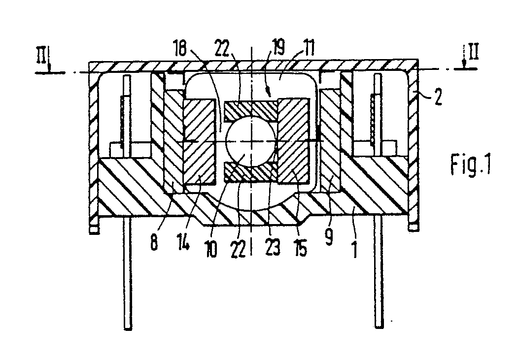
Description
Die Erfindung bezieht sich auf ein elektromagnetisches Relais gemäß dem Oberbegriff des Anspruchs 1.The invention relates to an electromagnetic relay according to the preamble of claim 1.
Ein derartiges Relais ist aus der FR-PS 1 080 986 bekannt. Bei diesem bekannten Relais schlagen die Polplatten direkt am Innenschenkel an. Dies hat zur Folge, daß der bei Relais an sich bekannte Klebeeffekt auftritt, d.h. nach dem Anziehen klebt der Anker auch nach Ausschalten der Betriebsspannung infolge des Restmagnetismus des Joches und des Ankers. Diese Kraft muß beim Zurückbewegen des Ankers überwunden werden. Bei unipolaren Relais ist zu diesem Zweck eine Rückholfederkraft vorgesehen, die wiederum eine höhere Ansprechleistung erfordert. Bei bipolaren Relais muß die Ansprechleistung in beiden Richtungen entsprechend erhöht werden. Diese Nachteile versucht man durch solche konstruktive Mittel auszugleichen, welche zwischen Joch und Anker einen definierten Luftspalt sicherstellen. So ist es bereits bekannt, auf dem Anker einen kleinen am Joch anschlagenden Kunststoffpilz anzubringen, der einen definierten Abstand zwischen Anker und Joch gewährleistet und zugleich eine Dämpfung des Ankeranschlags bewirkt.Such a relay is known from FR-PS 1 080 986. In this known relay, the pole plates strike directly on the inner leg. The result of this is that the adhesive effect known per se in relays occurs, ie after tightening the armature sticks even after the operating voltage has been switched off due to the residual magnetism of the yoke and the armature. This force must be overcome when the anchor is moved back. For unipolar relays, a return spring force is provided for this purpose, which in turn requires a higher response power. With bipolar relays, the response power must be increased accordingly in both directions. Attempts are made to compensate for these disadvantages by means of constructive means which ensure a defined air gap between the yoke and anchor. It is already known to attach a small plastic mushroom to the yoke, the one ensures defined distance between anchor and yoke and at the same time dampens the anchor stop.
Mit der Erfindung soll die Aufgabe gelöst werden, das Kleben des Ankers am Joch bei gleichzeitiger Geräuschdämpfung durch eine besonders einfache Konstruktion zu erreichen.The object of the invention is to achieve the gluing of the armature to the yoke with simultaneous noise reduction by means of a particularly simple construction.
Gelöst wird diese Aufgabe durch die im Kennzeichen des Anspruchs 1 angegebenen Merkmale. Diese Lösung gestattet es, den Luftspalt bereits bei der Herstellung des Spulenkörpers ohne zusätzlichen Aufwand zu bestimmen. Der Luftspalt kann sehr genau eingehalten werden, da die Abmessungen der Anschlagrippen in Spritzgußtechnik aus Kunststoff genau herstellbar sind.This object is achieved by the features specified in the characterizing part of claim 1. This solution allows the air gap to be determined without additional effort during the manufacture of the coil former. The air gap can be maintained very precisely, since the dimensions of the stop ribs can be produced precisely from plastic using injection molding technology.
Weitere vorteilhafte Ausgestaltungen der Erfindung sind in den Unteransprüchen angegeben und nachfolgend anhand eines in der Zeichnung veranschaulichten Ausführungsbeispiels beschrieben. Es zeigen:
- Fig. 1 den Querschnitt des Ausführungsbeispieles, das entlang der Linie I-I in Fig. 2 geschnitten ist,
- Fig. 2 die Draufsicht auf das Ausführungsbeispiel, das entlang der Linie II-II in Fig. 1 geschnitten ist, und
- Fig. 3 die Seitenansicht des Ausführungsbeispiels, das entlang der Linie III-III in Fig. 2 geschnitten ist.
- 1 shows the cross section of the exemplary embodiment, which is cut along the line II in FIG. 2,
- Fig. 2 is a plan view of the embodiment which is cut along the line II-II in Fig. 1, and
- Fig. 3 is a side view of the embodiment which is cut along the line III-III in Fig. 2.
In Fig. 1 bildet das Bodenteil 1 zusammen mit dem schachtelartigen Deckel 2 das Relaisgehäuse. Der Bodenteil 1 besitzt im Abstand und parallel zueinander angeordnete, nach oben ragende Trennwände 101. Zwischen diesen ist der Elektromagnet angeordnet. Er besteht aus dem Spulenkörper 3 mit der Wicklung 4, einem E-förmigen Joch 5 aus einem U-förmig gebogenen hochkant stehenden Flachmaterial, das mit den zwei Jochaußenschenkeln 5′ den Spulenkörper 3 umgibt. An der Basis 6 des Jochs 5 ist, wie in Fig. 2 zu erkennen, der im Querschnitt kreisförmig oder elliptisch ausgebildete, den Mittelschenkel des E-förmigen Jochs 5 bildende Jochkern 7 befestigt. Dieser ragt durch den Spulenkörper 3 hindurch. Die freien Schenkelenden 8 und 9 der Jochaußenschenkel 5′ und das freie Ende 10 des Jochkerns 7 ragen über den Spulenflansch 11 des Spulenkörpers 3 hinaus.In Fig. 1, the bottom part 1 together with the box-
Der Anker 12 des Relais besteht aus dem Querschieber 13 aus Isolierstoff, der senkrecht zur Längsrichtung des Joches 5 verschiebbar gelagert ist.The
In dem Querschieber 12 sind senkrecht zu seiner Verschieberichtung zwei parallel zueinander und mit Abstand voneinander angeordnete Polplatten 14 und 15 aus ferromagnetischem Werkstoff vorgesehen. Die aus dem Querschieber 13 herausstehenden Teile 16 und 17 der Polplatten 14, 15 ragen jeweils in einen Zwischenraum 18 und 19 zwischen den freien Schenkelenden 8 und 9 und dem Ende 10 des Jochkerns 7.In the
In die Aussparung 20 des Querschiebers 13 ist der zweipolig magnetisierte Permanentmagnet 21 so eingesetzt, daß ein Pol an der Polplatte 14, und der andere Pol an der Polplatte 15 anliegt. Die beiden Polplatten 14, 15 sind also gegenpolig magnetisiert, so daß das Relais eine bipolare Wirkung besitzt.In the
Damit beim Ansprechen des Relais zwischen einer der Polplatten 14 oder 15 und dem Jochkern 7 jeweils ein geringer Spalt bestehen bleibt, der das Kleben der Polplatte am Jochkern 7 verhindert, sind an gegenüberliegenden Seiten des Jochkerns 7 am Spulenflansch 11 senkrecht abstehende Anschlagrippen 22 (Fig. 1) angebracht. Diese sind z.B. bei der Herstellung des Spulenkörpers 3 mit angeformt.So that when the relay responds between one of the
Wie aus den Figuren 1 und 3 zu erkennen, haben die Anschlagrippen 22 eine plattenförmige Gestalt. Sie sind so breit, daß sie auf beiden Seiten des Jochkerns 7 überstehen, damit die Polplatte 14 oder 15 an der Anschlagrippe 22 gedämpft anschlagen kann und zwischen Polplatte 14 oder 15 und dem Jochkern 7 ein Spalt 23 bestehen bleibt. Die Breite der Anschlagrippen 22 ist so bemessen, daß die Größe des Spalts 23 etwa 0,05 bis 1 mm beträgt.As can be seen from FIGS. 1 and 3, the
Wenn das Relais als gepoltes monostabiles Relais ausgebildet ist, dann sollten die Anschlagrippen 22 auf beiden Seiten unterschiedlich stark überstehend ausgebildet sein und zwar derart, daß der Spalt 23 in Ruhelage des Ankers 12 kleiner als in der Arbeitslage ist. Die Maßnahme verhindert das Kleben des Ankers in der Arbeitslage und verbessert die Rückführung des Ankers in die Ruhelage.If the relay is designed as a polarized monostable relay, then the
Der Querschnitt des Jochkerns 7 kann auch quadratisch oder rechteckig ausgebildet sein. Wenn er elliptisch ausgebildet ist, dann sollte die Hauptachse oder die Nebenachse der Ellipse in Verschieberichtung des Ankers verlaufen.The cross section of the
Claims (4)
gekennzeichnet durch folgende Merkmale:
- am freien Ende (10) des Jochkerns (7) ist wenigstens eine Anschlagrippe (22) vorgesehen,
- die Anschlagrippe (22) ist breiter als die Dicke des Jochkerns (7) und ragt zu beiden Seiten über den Jochkern (7) hinaus.1. Electromagnetic relay with an E-shaped yoke having air gaps between the ends of the yoke legs and an armature which can be displaced transversely to the yoke and consists of a permanent magnet with pole plates, the ends of which dip into the air gaps,
characterized by the following features:
- At the free end (10) of the yoke core (7) at least one stop rib (22) is provided,
- The stop rib (22) is wider than the thickness of the yoke core (7) and protrudes on both sides beyond the yoke core (7).
Applications Claiming Priority (2)
| Application Number | Priority Date | Filing Date | Title |
|---|---|---|---|
| DE3818021 | 1988-05-27 | ||
| DE19883818021 DE3818021A1 (en) | 1988-05-27 | 1988-05-27 | ELECTROMAGNETIC RELAY |
Publications (2)
| Publication Number | Publication Date |
|---|---|
| EP0343554A2 true EP0343554A2 (en) | 1989-11-29 |
| EP0343554A3 EP0343554A3 (en) | 1990-03-14 |
Family
ID=6355240
Family Applications (1)
| Application Number | Title | Priority Date | Filing Date |
|---|---|---|---|
| EP89109150A Withdrawn EP0343554A3 (en) | 1988-05-27 | 1989-05-20 | Electromagnetic relay |
Country Status (2)
| Country | Link |
|---|---|
| EP (1) | EP0343554A3 (en) |
| DE (1) | DE3818021A1 (en) |
Family Cites Families (4)
| Publication number | Priority date | Publication date | Assignee | Title |
|---|---|---|---|---|
| FR1319342A (en) * | 1962-01-16 | 1963-03-01 | Cie De Construction Electr | Improvements to polarized relays, associated with differential circuit breakers |
| DE1690041A1 (en) * | 1967-09-01 | 1971-01-28 | Siemens Ag | Electromagnetic switching device |
| US4740771A (en) * | 1986-08-26 | 1988-04-26 | Matsushita Electric Works, Ltd. | Armature biasing means in an electromagnetic relay |
| DE3637115A1 (en) * | 1986-10-31 | 1988-05-05 | Standard Elektrik Lorenz Ag | POLED FLAT RELAY |
-
1988
- 1988-05-27 DE DE19883818021 patent/DE3818021A1/en not_active Withdrawn
-
1989
- 1989-05-20 EP EP89109150A patent/EP0343554A3/en not_active Withdrawn
Also Published As
| Publication number | Publication date |
|---|---|
| EP0343554A3 (en) | 1990-03-14 |
| DE3818021A1 (en) | 1989-11-30 |
Similar Documents
| Publication | Publication Date | Title |
|---|---|---|
| DE60025552T2 (en) | Coaxial relay | |
| EP0129068B1 (en) | Miniaturised electromagnetic relay, and method for its manufacture | |
| DE3406832C2 (en) | Clapper armature relay | |
| DE3586200T2 (en) | ELECTROMAGNETIC RELAY. | |
| DE3132239C2 (en) | Electromagnetic relay | |
| DE3630467A1 (en) | RELAY, IN PARTICULAR SMALL RELAY | |
| DE2449457C3 (en) | Clapper armature relay | |
| DE2830390C2 (en) | relay | |
| EP0203496B1 (en) | Electromagnetic relay | |
| DE3783834T2 (en) | ELECTROMAGNETIC RELAY. | |
| DE2811378C2 (en) | ||
| DE3047608C2 (en) | Electromagnetic relay | |
| EP0072976A1 (en) | Polarised electromagnetic relay | |
| EP0343554A2 (en) | Electromagnetic relay | |
| DE1934624C3 (en) | Electromagnetic relay | |
| DE2146407C3 (en) | Flat relay in miniature design | |
| DE3637115A1 (en) | POLED FLAT RELAY | |
| DE3046947C2 (en) | ||
| DE3528090C1 (en) | Electromagnetic relay | |
| DE10261473B4 (en) | Electromagnetic relay | |
| DE3328684C1 (en) | Armature retaining spring for DIL relays | |
| EP0068391A2 (en) | Miniaturised polarised electromagnetic relay | |
| EP0795186B1 (en) | Electromagnet switch | |
| DE2022584B2 (en) | Miniature electromagnet with U shaped yoke member - is designed to facilitate easy exchange of the excitation coil unit | |
| DE4143063C2 (en) | Miniature electromagnet and its use as a relay |
Legal Events
| Date | Code | Title | Description |
|---|---|---|---|
| PUAI | Public reference made under article 153(3) epc to a published international application that has entered the european phase |
Free format text: ORIGINAL CODE: 0009012 |
|
| AK | Designated contracting states |
Kind code of ref document: A2 Designated state(s): AT BE DE ES FR GB SE |
|
| PUAL | Search report despatched |
Free format text: ORIGINAL CODE: 0009013 |
|
| AK | Designated contracting states |
Kind code of ref document: A3 Designated state(s): AT BE DE ES FR GB SE |
|
| STAA | Information on the status of an ep patent application or granted ep patent |
Free format text: STATUS: THE APPLICATION IS DEEMED TO BE WITHDRAWN |
|
| 18D | Application deemed to be withdrawn |
Effective date: 19900915 |