EP0343370B1 - Réduction de l'effet de bord par lissage en récepteurs numériques - Google Patents
Réduction de l'effet de bord par lissage en récepteurs numériques Download PDFInfo
- Publication number
- EP0343370B1 EP0343370B1 EP89106901A EP89106901A EP0343370B1 EP 0343370 B1 EP0343370 B1 EP 0343370B1 EP 89106901 A EP89106901 A EP 89106901A EP 89106901 A EP89106901 A EP 89106901A EP 0343370 B1 EP0343370 B1 EP 0343370B1
- Authority
- EP
- European Patent Office
- Prior art keywords
- data
- edge
- signal
- paths
- sum
- Prior art date
- Legal status (The legal status is an assumption and is not a legal conclusion. Google has not performed a legal analysis and makes no representation as to the accuracy of the status listed.)
- Expired - Lifetime
Links
- 238000009499 grossing Methods 0.000 title description 15
- 230000000694 effects Effects 0.000 title description 3
- 230000009467 reduction Effects 0.000 title description 2
- 230000003595 spectral effect Effects 0.000 claims description 23
- 238000000034 method Methods 0.000 claims description 21
- 238000012545 processing Methods 0.000 claims description 21
- 238000006243 chemical reaction Methods 0.000 claims description 3
- 238000001228 spectrum Methods 0.000 description 15
- 238000001514 detection method Methods 0.000 description 11
- 238000013459 approach Methods 0.000 description 5
- 238000003708 edge detection Methods 0.000 description 5
- 230000006870 function Effects 0.000 description 4
- 230000008569 process Effects 0.000 description 4
- 238000010183 spectrum analysis Methods 0.000 description 4
- 230000007704 transition Effects 0.000 description 3
- 238000004458 analytical method Methods 0.000 description 2
- 230000005540 biological transmission Effects 0.000 description 2
- 230000000875 corresponding effect Effects 0.000 description 2
- 238000010586 diagram Methods 0.000 description 2
- 230000003139 buffering effect Effects 0.000 description 1
- 238000004891 communication Methods 0.000 description 1
- 230000002596 correlated effect Effects 0.000 description 1
- 230000003111 delayed effect Effects 0.000 description 1
- 238000009795 derivation Methods 0.000 description 1
- 238000005457 optimization Methods 0.000 description 1
- 238000012805 post-processing Methods 0.000 description 1
- 230000008672 reprogramming Effects 0.000 description 1
- 238000005070 sampling Methods 0.000 description 1
- 230000035945 sensitivity Effects 0.000 description 1
- 230000009131 signaling function Effects 0.000 description 1
- 230000002123 temporal effect Effects 0.000 description 1
- 238000012360 testing method Methods 0.000 description 1
Images
Classifications
-
- H—ELECTRICITY
- H03—ELECTRONIC CIRCUITRY
- H03H—IMPEDANCE NETWORKS, e.g. RESONANT CIRCUITS; RESONATORS
- H03H17/00—Networks using digital techniques
- H03H17/02—Frequency selective networks
Definitions
- This invention relates to methods and apparatus for improved detection, analysis, and discrimination of signals in receiving devices.
- these methods and apparatus reduce the undesirable effects of sharp signal pulses, called edges, from strong signal emitters, allowing for greater dynamic ranges in detection.
- Radar and sonar receivers provide good examples of such detection devices. These receivers seek to locate and identify all emitters in their area, including both strong and weak signal sources. However, certain obstacles prevent precise and complete tracking. In particular, signals which turn suddenly on or off during reception and processing tend to drown out weaker signals, making their detection and discrimination much more difficult.
- Document US-A-4 410 955 is concerned with a similar problem. It discloses an apparatus to be used in communication systems where digital data are employed as the modulating waveform for a radio transmitter.
- a data stream comprises a binary sequence of equal time interval bits, i.e. of successive low and high values.
- the resulting digital waveform is therefore a series of rectangular pulses with very abrupt transition, these transitions resulting in the generation of undesired spurious sidebands or splatter thus increasing the radio frequency bandwidth occupied by the transmission.
- the actual bit to be transmitted next is compared with the previously transmitted bit in a decoder circuit.
- both bits are equal, i.e. either low or high
- the actual bit is converted to the analog level and transmitted.
- the decoder detects a low-to-high or high-to-low transition, such an edge is replaced by a portion of a stored, gradually varying waveform in order to reduce the spectral splatter in the pulse signal waveform.
- a higher clock rate is used for the edge-substituting waveform than for the bit stream itself.
- results of an FFT are often expressed in a power spectrum chart, graphing the amplitude weighting for each fourier sine wave component as a function of that component's frequency (sometimes called a frequency bin or an FFT "filter").
- An FFT of a simple sine wave yields a single amplitude point on a power spectrum, at exactly that frequency.
- the power spectrum will generally be more complex, but will have a peak centered on the emitter's principal frequency.
- an apparatus for reducing spectral splatter in a signal receiver is characterized by:
- This invention thus provides methods and apparatus for reducing spectral splatter produced in a digital receiver due to receiving edges from strong digital emitters.
- These apparatus include means for digitizing and buffering incoming signal data.
- this data includes a plurality of signals of different frequency and comprising complex-valued numbers.
- these apparatus provide means for ascertaining the presence of one or more edges in the same digitized data. If an edge occurs, special values or sets of weights are applied to the buffered data which smooth out the discontinuity in the edge.
- FFT Fast Fourier Transform
- the frequency spread caused by the edge is quenched, and the signal-to-noise ratios for signals of other, and especially weaker, frequencies are increased.
- the strong edge and spectral splatter associated with a signal of a given frequency no longer drowns out weaker signals at other frequencies.
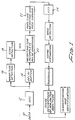
- FIG. 1 represents a block diagram of the flow of data in the present invention.
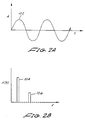
- FIGS. 2A and 2B show graphs of a strong signal over time and its corresponding Fourier power spectrum, with a superimposed weaker signal.
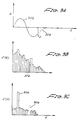
- FIGS. 3A, 3B, and 3C show graphs of a strong signal over time with a pulse edge and the corresponding Fourier power spectrums both with and without edge smoothing.
- FIG. 1 shows a block diagram for a digital radar receiver.
- the Analog-Digital Conversion (ADC) Block 12 receives and converts analog data 10 to digital information. The data is duplicated after this point, with one set of data delayed in a buffer 14 while the other set travels through the Edge Detection processing blocks 16 and 18. Within this path, the Magnitude Detection Block 16 forms real magnitudes out of the ADC complex number outputs, for use in recognizing edges.
- the real magnitude may be formed from the complex numbers in an approximate way, by taking (if the data is given by a + bi) the real value as Max[
- the Edge Detection Block 18 determines whether an edge is present or not. It performs this function in two stages. First, for each point j in the signal or data stream, clusters of data points located at some time n before the point are subtracted from clusters of data points located at some time n after the point. Thus, if some discontinuity should occur, subtracting points before and after the discontinuity would yield an offset.
- the offset b j After taking the positive value of the offset b j for the given point, it is compared with the offset values immediately before (b j-1 ) and immediately after (b j+1 ) the point in question. If the offset is larger than either of its neighbors and is larger than a threshold determined from the data itself, then an edge is declared at point j.
- weighted offset values b j can be calculated as follows: The summation bounds m and the offset n can be determined for particular applications to yield the most efficient (i.e. process timesaving) and accurate algorithm required. The resulting weighted values b j for each data point j can be used to detect a pulse edge.
- a pulse edge is declared if b j > b j+1 and b j > b j-1 and b j > t j , i.e. if b j is greater than its nearest neighbors and is greater than some threshold value determined by where parameter S determines the relative sensitivity for thresholding sharp edges.
- Min refers to taking the value of the minimum of the arguments within the brackets. Configuring the parameters used in the algorithms requires testing sample data and varying the parameters, m,n, and S until the best results are obtained, best meaning the lowest overall frequency noise from sharp edges.
- the algorithm described for determining the b j 's and for declaring pulse edges is just one example of various processing alternatives.
- the partial summation results used for ever jth data point as shown above can be kept in memory and updated easily for each incoming data point by adding and subtracting the data points in a buffer. This partial summing can save processing time.
- the Edge Detection Block 18 determines an edge through the above procedure, it sends an instruction to the Pulse Smoothing block 20 to apply the smoothing weights to the data's edge.
- the weights are applied by multiplying a set number of the samples around the edge at sample j by a fixed weight set centered on data sample j.
- the weighting algorithm can be varied for specific system goals, requiring a tailoring of the weights to the particular data, their dynamic range, and to the FTT algorithms being used.
- the weighting used is represented by W s (t), given by: where f s is the data sampling rate and N is the number of samples weighted. ⁇ is the pulse rise time.
- normal pre-FFT amplitude weights 22 are applied (for example Dolph-Chebyshev weights) which reduce sidelobes for the FFT being used.
- An FFT normally processes a set number of data points at a time, the number of data points used being called the "window". If the FFT window doesn't quite match the weighted data stream, some data turning 22 may be required to properly match the weighted sample size to the FFT window.
- a whole collection of possible weights could be preset and used depending on the location of the edge within the FFT processing window. This can save processing time by calculating in advance all possible weighting combinations.
- the edge smoothing weights and the single set of amplitude (Dolph-Chebyshev) weights are replaced by a group of combined weights, each pre-optimized for a particular location of the pulse edge within the FFT processing window.
- the two approaches discussed have benefits and drawbacks.
- the first approach multiplying when detected each edge by the weights, has the greater flexibility. Any number of edges within a given window can be smoothed, and modularity allows different post-processing to be done without reprogramming or restructuring the smoothing step.
- the second approach having preset weighting sets, implements the edge smoothing into a total processing system, trading flexibility for processing speed and pre-optimization.
- Magnitude detection after the FFT is performed, determines the strengths of each frequency given in the filters of the FFT.
- Each filter bin represents a possible signal and its relative strength determines how likely it is an actual signal from an existing emitter.
- the noise estimation stage determines the noise level of all the filter bins in order to form a reasonable thresholding value for removing noise from true signals.
- the removal process is performed at the thresholding stage, using the threshold already determined.
- the pulse descriptor stage calculates the angle and times of arrival of given frequency signals, their pulse widths and their amplitudes or strengths. Determining the angle of an emitter often requires a plurality of antennas or detectors to triangulate the signal source. On the basis of these descriptors, time histories of pulses are created in the classification and identification stage, so that received pulses are correlated with emitters and these emitters may be tracked in time.
- FIGS. 2 and 3 illustrate a simple operation of the present invention.
- FIG. 2A reveals a strong signal sine wave 102, graphed with its amplitude A over time t.
- FIG. 2B shows the power spectrum resulting from performing an FFT upon the strong signal.
- F(f) represents the relative strength of the incoming signals versus frequency.
- the tall bin 104 is the amplitude of the strong signal; smaller bin 106 represents a relatively weak signal detected along with the stronger signal. In this case, both signals are easy to detect and distinguish from one another.
- FIG. 3A represents the same strong signal 202 as FIG. 2A but here the signal suddenly cuts off at time t designated t0.
- a dashed line 203 indicates the smoothing of the discontinuity which the present invention provides.
- FIG. 3B shows a power spectrum of the strong signal and its edge without any smoothing, having very FFT filter or bin excited. The noise or spectral splatter resulting from the signal edge washes out the small signal 206 shown by the dotted lines.
- FIG. 3C shows the power spectrum resulting after edge smoothing, the noise being much smaller in strength.
- Edge smoothing greatly reduces the FFT noise or spectral splatter, allowing detection of smaller signals and thereby increasing the dynamic range for detection.
Landscapes
- Physics & Mathematics (AREA)
- Engineering & Computer Science (AREA)
- Computer Hardware Design (AREA)
- Mathematical Physics (AREA)
- Radar Systems Or Details Thereof (AREA)
- Noise Elimination (AREA)
- Image Processing (AREA)
- Signal Processing For Digital Recording And Reproducing (AREA)
Claims (14)
- Un procédé pour réduire la pollution spectrale dans un processeur de signal, caractérisé par les étapes suivantes :- on traite des données numériques dans deux voies (16/18, 14);- dans la première (16/18) des deux voies, on détermine le moment auquel les données présentent un front; et- lorsqu'on détermine l'existence d'un front dans les données dans la première voie, on applique des poids à ce front dans la seconde (14) des deux voies, les poids appliqués étant tels qu'ils réduisent la pollution spectrale qui est due à la présence du front précité lorsque les données font l'objet d'une analyse spectrale.
- Un procédé pour réduire la pollution spectrale dans un récepteur de signal, caractérisé par les étapes suivantes :- on reçoit des données de signal sous forme numérique,- on traite ces données dans deux voies (16/18, 14);- dans une première (16/18) des voies, on convertit les données numériques en données à valeurs réelles et on détermine le moment auquel une série des données à valeurs réelles présente un front;- dans la seconde (14) des voies, on retarde les données numériques jusqu'à ce que le traitement des données numériques dans la première (16/18) des voies soit terminé et on détermine des valeurs de pondération pour l'application aux fronts détectés; et- dans la seconde (14) des voies, on applique les valeurs de pondération aux fronts détectés, ces valeurs de pondération étant telles qu'elles réduisent la pollution spectrale qui est due à la présence du front lorsque les données font l'objet d'une analyse spectrale.
- Le procédé de la revendication 1 ou 2, caractérisé en ce qu'on sélectionne les valeurs de pondération de façon à réduire la pollution spectrale lorsque les données font l'objet d'une analyse spectrale.
- Le procédé de l'une quelconque des revendications 1 à 3, caractérisé en ce qu'on reçoit des signaux qui consistent en ondes électromagnétiques.
- Le procédé de l'une quelconque des revendications 1 à 4, caractérisé en ce qu'on convertit sous forme numérique les données de signal analogiques reçues (10).
- Le procédé de l'une quelconque des revendications 1 à 5, caractérisé en ce qu'on traite les données pondérées en effectuant une transformation de Fourier rapide (24).
- Le procédé de l'une quelconque des revendications 2 à 6, caractérisé en ce que la détermination du moment auquel une série des données à valeurs réelles présente un front comprend :- le calcul de valeurs de décalage bj à partir des données à valeurs réelles appelées aj, pour chaque point j dans le train de données; et- la détermination du moment auquel l'une des valeurs bj est supérieure à ses deux voisines les plus proches, bj-1 et bj+1 et est supérieure à une valeur de seuil tj, ce qui fait que aj consiste en un front.
- Le procédé de la revendication 7, caractérisé en ce que le calcul de bj comprend les opérations suivantes :- on calcule une première somme de 2m+1 des aj autour de aj+n;- on calcule une seconde somme de 2m+1 des aj autour de aj-n; et- on soustrait la seconde somme de la première somme.
- Le procédé de l'une quelconque des revendications 6 à 8, caractérisé en ce qu'on forme une valeur de seuil tj par les opérations suivantes :- on calcule une première somme de 2m+1 des aj autour de aj+n;- on calcule une seconde somme de 2m+1 des aj autour de aj-n; et- on prend tj égal à S fois le minimum de la première somme ou de la seconde somme.
- Un appareil pour réduire la pollution spectrale dans un récepteur de signal, caractérisé par :- des moyens pour recevoir des données de signal sous forme numérique;- des moyens (16) pour convertir ces données en données à valeurs réelles;- des moyens pour déterminer le moment auquel une série des données à valeurs réelles présente un front;- des moyens (14) pour retarder un second ensemble des données de signal jusqu'à ce que les moyens de conversion (16) et les moyens de détermination (18) aient terminé le traitement des données de signal; et- des moyens (20) pour appliquer des valeurs de pondération au front du second ensemble de données de signal, ces valeurs de pondération étant telles qu'elles réduisent la pollution spectrale qui est due à la présence du front lorsque les données font l'objet d'une analyse spectrale.
- L'appareil de la revendication 10, caractérisé en ce que le signal consiste en une onde électromagnétique.
- L'appareil de la revendication 10 ou 11, caractérisé en ce que les moyens de réception de données de signal consistent en un convertisseur analogique-numérique (12).
- L'appareil de l'une quelconque des revendications 10 à 12, caractérisé en ce que les valeurs de pondération réduisent la pollution spectrale lorsque les données sont traitées.
- L'appareil de l'une quelconque des revendications 10 à 13, caractérisé en ce que les moyens de traitement des données de signal pondérées sont constitués par des moyens de transformation de Fourier rapide (24).
Applications Claiming Priority (2)
| Application Number | Priority Date | Filing Date | Title |
|---|---|---|---|
| US07/185,018 US4958361A (en) | 1988-04-22 | 1988-04-22 | Edge effect reduction by smoothing in digital receivers |
| US185018 | 1988-04-22 |
Publications (3)
| Publication Number | Publication Date |
|---|---|
| EP0343370A2 EP0343370A2 (fr) | 1989-11-29 |
| EP0343370A3 EP0343370A3 (en) | 1990-09-19 |
| EP0343370B1 true EP0343370B1 (fr) | 1994-08-24 |
Family
ID=22679214
Family Applications (1)
| Application Number | Title | Priority Date | Filing Date |
|---|---|---|---|
| EP89106901A Expired - Lifetime EP0343370B1 (fr) | 1988-04-22 | 1989-04-18 | Réduction de l'effet de bord par lissage en récepteurs numériques |
Country Status (6)
| Country | Link |
|---|---|
| US (1) | US4958361A (fr) |
| EP (1) | EP0343370B1 (fr) |
| AU (1) | AU612823B2 (fr) |
| CA (1) | CA1319959C (fr) |
| DE (1) | DE68917641T2 (fr) |
| ES (1) | ES2058376T3 (fr) |
Families Citing this family (8)
| Publication number | Priority date | Publication date | Assignee | Title |
|---|---|---|---|---|
| US4984253A (en) * | 1988-06-03 | 1991-01-08 | Hughes Aircraft Company | Apparatus and method for processing simultaneous radio frequency signals |
| US5216696A (en) * | 1989-12-22 | 1993-06-01 | Comsat Laboratories | Programmable noise bandwidth reduction by means of digital averaging |
| JP2768548B2 (ja) * | 1990-11-09 | 1998-06-25 | シャープ株式会社 | パネルディスプレイ表示装置 |
| US5367539A (en) * | 1991-12-31 | 1994-11-22 | At&T Bell Laboratories | Digital block processor for processing a plurality of transmission channels in a wireless radiotelephony system |
| US5381150A (en) * | 1993-05-07 | 1995-01-10 | Trw Inc. | Partial intercept LPI (low probability of intercept) reconnaissance system |
| US6249796B1 (en) * | 1998-12-08 | 2001-06-19 | Siemens Medical Systems, Inc. | Real-time technique for reducing the settling time of a high pass filter |
| US6515527B2 (en) * | 2001-06-22 | 2003-02-04 | Sun Microsystems, Inc. | Method for smoothing dI/dT noise due to clock transitions |
| CN102841336A (zh) * | 2012-09-04 | 2012-12-26 | 中船重工鹏力(南京)大气海洋信息系统有限公司 | 高频地波雷达多频信号相参接收机 |
Citations (1)
| Publication number | Priority date | Publication date | Assignee | Title |
|---|---|---|---|---|
| US4410955A (en) * | 1981-03-30 | 1983-10-18 | Motorola, Inc. | Method and apparatus for digital shaping of a digital data stream |
Family Cites Families (4)
| Publication number | Priority date | Publication date | Assignee | Title |
|---|---|---|---|---|
| GB1448697A (en) * | 1973-09-25 | 1976-09-08 | Post Office | Non-linear correction of waveforms |
| US4358788A (en) * | 1981-02-27 | 1982-11-09 | Rca Corporation | Legibility for alpha-mosaic characters |
| DE3278915D1 (en) * | 1981-12-31 | 1988-09-22 | Secr Defence Brit | Receivers for navigation satellite systems |
| JPH055725Y2 (fr) * | 1987-02-06 | 1993-02-15 |
-
1988
- 1988-04-22 US US07/185,018 patent/US4958361A/en not_active Expired - Lifetime
-
1989
- 1989-04-18 DE DE68917641T patent/DE68917641T2/de not_active Expired - Fee Related
- 1989-04-18 ES ES89106901T patent/ES2058376T3/es not_active Expired - Lifetime
- 1989-04-18 EP EP89106901A patent/EP0343370B1/fr not_active Expired - Lifetime
- 1989-04-18 AU AU33163/89A patent/AU612823B2/en not_active Ceased
- 1989-04-21 CA CA000597456A patent/CA1319959C/fr not_active Expired - Fee Related
Patent Citations (1)
| Publication number | Priority date | Publication date | Assignee | Title |
|---|---|---|---|---|
| US4410955A (en) * | 1981-03-30 | 1983-10-18 | Motorola, Inc. | Method and apparatus for digital shaping of a digital data stream |
Also Published As
| Publication number | Publication date |
|---|---|
| CA1319959C (fr) | 1993-07-06 |
| US4958361A (en) | 1990-09-18 |
| EP0343370A3 (en) | 1990-09-19 |
| AU3316389A (en) | 1989-10-26 |
| ES2058376T3 (es) | 1994-11-01 |
| EP0343370A2 (fr) | 1989-11-29 |
| DE68917641T2 (de) | 1995-04-13 |
| AU612823B2 (en) | 1991-07-18 |
| DE68917641D1 (de) | 1994-09-29 |
Similar Documents
| Publication | Publication Date | Title |
|---|---|---|
| US10879946B1 (en) | Weak signal processing systems and methods | |
| JP6026531B2 (ja) | レーダー用デジタル受信機を用いるレーダーパルス検出 | |
| US6043771A (en) | Compact, sensitive, low power device for broadband radar detection | |
| US7035311B2 (en) | Apparatus and method for a digital, wideband, intercept and analysis processor for frequency hopping signals | |
| US5235339A (en) | Radar target discrimination systems using artificial neural network topology | |
| US9991908B2 (en) | Blind source separation of signals having low signal-to-noise ratio | |
| EP3489710A1 (fr) | Suppression d'interférence radar | |
| KR100824552B1 (ko) | 수동 코히어런트 위치 확인 애플리케이션에서 특징을 검출 및 추출하는 시스템 및 방법 | |
| WO2008094172A2 (fr) | Microcapteur radar pour la détection, la poursuite et le classement | |
| US6356600B1 (en) | Non-parametric adaptive power law detector | |
| WO2021145929A1 (fr) | Récepteur intelligent avec détection de compression et apprentissage automatique | |
| EP0343370B1 (fr) | Réduction de l'effet de bord par lissage en récepteurs numériques | |
| US9866422B1 (en) | Methods of blind source separation filter resource management | |
| KR101429361B1 (ko) | 차량용 레이더에서의 임펄스성 간섭 신호 제거 방법 및 이 방법을 수행하는 장치 | |
| US5793323A (en) | Two signal monobit electronic warfare receiver | |
| RU2549207C2 (ru) | Устройство обнаружения шумовых гидроакустических сигналов на основе квадратурного приемника | |
| US7336736B2 (en) | Method of detecting and processing pulsed signals in a radio signal | |
| US11391813B2 (en) | Method for detecting radar signals | |
| KR20160043437A (ko) | 차량용 레이더에서의 임펄스성 간섭 신호 검출 방법 및 장치 | |
| Erdogan et al. | Deinterleaving radar pulse train using neural networks | |
| US5418540A (en) | Method and apparatus for eliminating signal sidelobes from a received signal frame in a multichannel receiver | |
| RU2799480C1 (ru) | Способ обработки сигналов во временной и частотной областях | |
| Albaker et al. | Detection and parameters interception of a radar pulse signal based on interrupt driven algorithm | |
| Cai et al. | Research on Low SNR Mono-pulse Detection Algorithm for Space-borne Receiver | |
| Klaput et al. | A novel approach to estimation of Doppler frequencies of a time-varying communication channel |
Legal Events
| Date | Code | Title | Description |
|---|---|---|---|
| PUAI | Public reference made under article 153(3) epc to a published international application that has entered the european phase |
Free format text: ORIGINAL CODE: 0009012 |
|
| 17P | Request for examination filed |
Effective date: 19890511 |
|
| AK | Designated contracting states |
Kind code of ref document: A2 Designated state(s): DE ES FR GB IT SE |
|
| RIN1 | Information on inventor provided before grant (corrected) |
Inventor name: KRIKORIAN, KAPRIEL A. Inventor name: ROSEN, ROBERT A. |
|
| PUAL | Search report despatched |
Free format text: ORIGINAL CODE: 0009013 |
|
| AK | Designated contracting states |
Kind code of ref document: A3 Designated state(s): DE ES FR GB IT SE |
|
| RHK1 | Main classification (correction) |
Ipc: G01R 23/167 |
|
| 17Q | First examination report despatched |
Effective date: 19921021 |
|
| ITF | It: translation for a ep patent filed | ||
| GRAA | (expected) grant |
Free format text: ORIGINAL CODE: 0009210 |
|
| AK | Designated contracting states |
Kind code of ref document: B1 Designated state(s): DE ES FR GB IT SE |
|
| REF | Corresponds to: |
Ref document number: 68917641 Country of ref document: DE Date of ref document: 19940929 |
|
| REG | Reference to a national code |
Ref country code: ES Ref legal event code: FG2A Ref document number: 2058376 Country of ref document: ES Kind code of ref document: T3 |
|
| ET | Fr: translation filed | ||
| EAL | Se: european patent in force in sweden |
Ref document number: 89106901.5 |
|
| PGFP | Annual fee paid to national office [announced via postgrant information from national office to epo] |
Ref country code: FR Payment date: 19950309 Year of fee payment: 7 |
|
| PGFP | Annual fee paid to national office [announced via postgrant information from national office to epo] |
Ref country code: GB Payment date: 19950315 Year of fee payment: 7 |
|
| PGFP | Annual fee paid to national office [announced via postgrant information from national office to epo] |
Ref country code: SE Payment date: 19950320 Year of fee payment: 7 |
|
| PGFP | Annual fee paid to national office [announced via postgrant information from national office to epo] |
Ref country code: DE Payment date: 19950322 Year of fee payment: 7 |
|
| PGFP | Annual fee paid to national office [announced via postgrant information from national office to epo] |
Ref country code: ES Payment date: 19950410 Year of fee payment: 7 |
|
| PLBE | No opposition filed within time limit |
Free format text: ORIGINAL CODE: 0009261 |
|
| STAA | Information on the status of an ep patent application or granted ep patent |
Free format text: STATUS: NO OPPOSITION FILED WITHIN TIME LIMIT |
|
| 26N | No opposition filed | ||
| PG25 | Lapsed in a contracting state [announced via postgrant information from national office to epo] |
Ref country code: GB Effective date: 19960418 |
|
| PG25 | Lapsed in a contracting state [announced via postgrant information from national office to epo] |
Ref country code: SE Effective date: 19960419 Ref country code: ES Free format text: LAPSE BECAUSE OF NON-PAYMENT OF DUE FEES Effective date: 19960419 |
|
| GBPC | Gb: european patent ceased through non-payment of renewal fee |
Effective date: 19960418 |
|
| PG25 | Lapsed in a contracting state [announced via postgrant information from national office to epo] |
Ref country code: FR Effective date: 19961227 |
|
| PG25 | Lapsed in a contracting state [announced via postgrant information from national office to epo] |
Ref country code: DE Effective date: 19970101 |
|
| EUG | Se: european patent has lapsed |
Ref document number: 89106901.5 |
|
| REG | Reference to a national code |
Ref country code: FR Ref legal event code: ST |
|
| REG | Reference to a national code |
Ref country code: ES Ref legal event code: FD2A Effective date: 19990301 |
|
| PG25 | Lapsed in a contracting state [announced via postgrant information from national office to epo] |
Ref country code: IT Free format text: LAPSE BECAUSE OF NON-PAYMENT OF DUE FEES;WARNING: LAPSES OF ITALIAN PATENTS WITH EFFECTIVE DATE BEFORE 2007 MAY HAVE OCCURRED AT ANY TIME BEFORE 2007. THE CORRECT EFFECTIVE DATE MAY BE DIFFERENT FROM THE ONE RECORDED. Effective date: 20050418 |