EP0343365A2 - Vehicle brake installation - Google Patents
Vehicle brake installation Download PDFInfo
- Publication number
- EP0343365A2 EP0343365A2 EP89106787A EP89106787A EP0343365A2 EP 0343365 A2 EP0343365 A2 EP 0343365A2 EP 89106787 A EP89106787 A EP 89106787A EP 89106787 A EP89106787 A EP 89106787A EP 0343365 A2 EP0343365 A2 EP 0343365A2
- Authority
- EP
- European Patent Office
- Prior art keywords
- motor vehicle
- brake system
- vehicle brake
- flange
- brake
- Prior art date
- Legal status (The legal status is an assumption and is not a legal conclusion. Google has not performed a legal analysis and makes no representation as to the accuracy of the status listed.)
- Granted
Links
- 238000009434 installation Methods 0.000 title 1
- 238000007789 sealing Methods 0.000 claims description 11
- 239000011324 bead Substances 0.000 claims description 3
- 230000003321 amplification Effects 0.000 claims 1
- 238000003199 nucleic acid amplification method Methods 0.000 claims 1
- 230000007704 transition Effects 0.000 claims 1
- 238000004519 manufacturing process Methods 0.000 abstract description 3
- 230000005540 biological transmission Effects 0.000 description 3
- 230000006835 compression Effects 0.000 description 3
- 238000007906 compression Methods 0.000 description 3
- 230000003014 reinforcing effect Effects 0.000 description 3
- 238000010586 diagram Methods 0.000 description 2
- 230000001965 increasing effect Effects 0.000 description 2
- 239000012528 membrane Substances 0.000 description 2
- 238000005096 rolling process Methods 0.000 description 2
- 230000006399 behavior Effects 0.000 description 1
- 230000000903 blocking effect Effects 0.000 description 1
- 230000001419 dependent effect Effects 0.000 description 1
- 239000012530 fluid Substances 0.000 description 1
- 230000001939 inductive effect Effects 0.000 description 1
- 230000002787 reinforcement Effects 0.000 description 1
- 230000004044 response Effects 0.000 description 1
- 230000028838 turning behavior Effects 0.000 description 1
- 238000009423 ventilation Methods 0.000 description 1
- 238000013022 venting Methods 0.000 description 1
Images

Classifications
-
- B—PERFORMING OPERATIONS; TRANSPORTING
- B60—VEHICLES IN GENERAL
- B60T—VEHICLE BRAKE CONTROL SYSTEMS OR PARTS THEREOF; BRAKE CONTROL SYSTEMS OR PARTS THEREOF, IN GENERAL; ARRANGEMENT OF BRAKING ELEMENTS ON VEHICLES IN GENERAL; PORTABLE DEVICES FOR PREVENTING UNWANTED MOVEMENT OF VEHICLES; VEHICLE MODIFICATIONS TO FACILITATE COOLING OF BRAKES
- B60T13/00—Transmitting braking action from initiating means to ultimate brake actuator with power assistance or drive; Brake systems incorporating such transmitting means, e.g. air-pressure brake systems
- B60T13/10—Transmitting braking action from initiating means to ultimate brake actuator with power assistance or drive; Brake systems incorporating such transmitting means, e.g. air-pressure brake systems with fluid assistance, drive, or release
- B60T13/24—Transmitting braking action from initiating means to ultimate brake actuator with power assistance or drive; Brake systems incorporating such transmitting means, e.g. air-pressure brake systems with fluid assistance, drive, or release the fluid being gaseous
- B60T13/46—Vacuum systems
- B60T13/52—Vacuum systems indirect, i.e. vacuum booster units
- B60T13/57—Vacuum systems indirect, i.e. vacuum booster units characterised by constructional features of control valves
-
- B—PERFORMING OPERATIONS; TRANSPORTING
- B60—VEHICLES IN GENERAL
- B60T—VEHICLE BRAKE CONTROL SYSTEMS OR PARTS THEREOF; BRAKE CONTROL SYSTEMS OR PARTS THEREOF, IN GENERAL; ARRANGEMENT OF BRAKING ELEMENTS ON VEHICLES IN GENERAL; PORTABLE DEVICES FOR PREVENTING UNWANTED MOVEMENT OF VEHICLES; VEHICLE MODIFICATIONS TO FACILITATE COOLING OF BRAKES
- B60T13/00—Transmitting braking action from initiating means to ultimate brake actuator with power assistance or drive; Brake systems incorporating such transmitting means, e.g. air-pressure brake systems
- B60T13/10—Transmitting braking action from initiating means to ultimate brake actuator with power assistance or drive; Brake systems incorporating such transmitting means, e.g. air-pressure brake systems with fluid assistance, drive, or release
- B60T13/66—Electrical control in fluid-pressure brake systems
- B60T13/72—Electrical control in fluid-pressure brake systems in vacuum systems or vacuum booster units
-
- B—PERFORMING OPERATIONS; TRANSPORTING
- B60—VEHICLES IN GENERAL
- B60T—VEHICLE BRAKE CONTROL SYSTEMS OR PARTS THEREOF; BRAKE CONTROL SYSTEMS OR PARTS THEREOF, IN GENERAL; ARRANGEMENT OF BRAKING ELEMENTS ON VEHICLES IN GENERAL; PORTABLE DEVICES FOR PREVENTING UNWANTED MOVEMENT OF VEHICLES; VEHICLE MODIFICATIONS TO FACILITATE COOLING OF BRAKES
- B60T8/00—Arrangements for adjusting wheel-braking force to meet varying vehicular or ground-surface conditions, e.g. limiting or varying distribution of braking force
- B60T8/32—Arrangements for adjusting wheel-braking force to meet varying vehicular or ground-surface conditions, e.g. limiting or varying distribution of braking force responsive to a speed condition, e.g. acceleration or deceleration
- B60T8/34—Arrangements for adjusting wheel-braking force to meet varying vehicular or ground-surface conditions, e.g. limiting or varying distribution of braking force responsive to a speed condition, e.g. acceleration or deceleration having a fluid pressure regulator responsive to a speed condition
- B60T8/44—Arrangements for adjusting wheel-braking force to meet varying vehicular or ground-surface conditions, e.g. limiting or varying distribution of braking force responsive to a speed condition, e.g. acceleration or deceleration having a fluid pressure regulator responsive to a speed condition co-operating with a power-assist booster means associated with a master cylinder for controlling the release and reapplication of brake pressure through an interaction with the power assist device, i.e. open systems
- B60T8/447—Reducing the boost of the power-assist booster means to reduce brake pressure
- B60T8/448—Reducing the boost of the power-assist booster means to reduce brake pressure the power-assist booster means being a vacuum or compressed air booster
-
- Y—GENERAL TAGGING OF NEW TECHNOLOGICAL DEVELOPMENTS; GENERAL TAGGING OF CROSS-SECTIONAL TECHNOLOGIES SPANNING OVER SEVERAL SECTIONS OF THE IPC; TECHNICAL SUBJECTS COVERED BY FORMER USPC CROSS-REFERENCE ART COLLECTIONS [XRACs] AND DIGESTS
- Y10—TECHNICAL SUBJECTS COVERED BY FORMER USPC
- Y10S—TECHNICAL SUBJECTS COVERED BY FORMER USPC CROSS-REFERENCE ART COLLECTIONS [XRACs] AND DIGESTS
- Y10S303/00—Fluid-pressure and analogous brake systems
- Y10S303/02—Brake control by pressure comparison
- Y10S303/03—Electrical pressure sensor
- Y10S303/04—Pressure signal used in electrical speed controlled braking circuit
Definitions
- the invention relates to a motor vehicle brake system with a vacuum brake booster which is operatively arranged between the brake pedal and master brake cylinder and has at least two working chambers separated from one another by a movable wall, the first of which can be connected to a vacuum source and the second can be ventilated via a control valve which can be actuated by means of a piston rod coupled to the brake pedal.
- wheel brake cylinders being connected to a primary and a secondary pressure chamber of the master brake cylinder via brake lines, with the sensors to be braked, which detect the rotational behavior of the wheels in order to determine a blockage, and their output signals to a central one
- Control electronics can be supplied, with their control signals for slip control in the brake lines inserted electromagnetically actuated pressure medium inlet and outlet valves can be controlled.
- Such a brake system is known for example from DE-OS 36 27 000.
- the special feature of this known brake system working with a hydraulic auxiliary pressure supply system is that, in order to be able to rapidly reduce the brake pressure generated by the master brake cylinder in a slip control case, the pistons of the master brake cylinder are also provided with central control valves that open pressure medium connections between a pressure medium reservoir and the pressure chambers of the master brake cylinder in the brake release position and close these pressure medium connections in the brake position, the brake lines being switched on via inflow lines into the check valves, are connected to the motor-driven pumps of the auxiliary pressure supply system, the suction connections of which are connected to the pressure medium reservoir via a suction line.
- pneumatic means are provided which, in a slip control case, ventilate the first working chamber and / or enable evacuation of the second working chamber in order to make the amplifying force of the vacuum brake booster effective or ineffective in a direction opposite to the actuating direction of the master brake cylinder.
- the pneumatic means are each formed by two 2/2-way valves which can be excited by a control signal from the central control electronics.
- a simplification of the structure of the motor vehicle brake system according to the invention is achieved in that the 2/2-way valves are designed as normally open and normally closed solenoid valves.
- the pneumatic means are connected to the second working chamber by means of a flange provided on the booster housing, which is provided with a pneumatic connection and with the booster housing and a control valve housing limited a ventilatable and evacuable space.
- control valve housing has an axial extension which is guided in a sealed manner in the flange.
- a particularly compact, inexpensive production of the subject of the invention is finally characterized in that the ventilable or evacuable space is separated from the ambient atmosphere by a bellows which extends between the flange and the piston rod.
- Fig. 1 shows a motor vehicle brake system with a vacuum brake booster 1, which is connected via a piston rod 11 in a known manner to a brake pedal 12.
- a tandem master brake cylinder 2 On the side of the vacuum brake booster 1 facing away from the piston rod 11, a tandem master brake cylinder 2 is provided, which is connected to a brake fluid reservoir, not shown.
- a first and a second brake circuit 17 and 16 are connected to the pressure chambers 80, 90 of the tandem master cylinder 2.
- the first brake circuit 17 connects the wheel brake cylinders of the two wheel brakes 20 and 21, which are only shown schematically, to the tandem master brake cylinder 2 via two solenoid valves 18, 19, which are designed as 2/2-way valves. Each of the two solenoid valves 18, 19 is here assigned to one of the two wheel brakes 20 or 21.
- the second brake circuit 16 connects the wheel brake cylinders of the further two wheel brakes 22, 23, also shown only schematically, to the tandem master brake cylinder 2 via two further solenoid valves 14, 24, which are also designed as 2/2-way valves.
- a sensor 25, 26, 27 and 28 is assigned to the front and rear wheel brakes 20, 21, 22 and 23, which are connected to central control electronics 33 via corresponding signal lines 29, 30, 31 and 32.
- the sensors 25, 26, 27 and 28, which can be designed, for example, as inductive sensors, monitor the wheel turning behavior and deliver corresponding signals to the control electronics 33 via the signal lines 29, 30, 31 and 32.
- the control electronics 33 are connected via control lines 34, 35, 36, 37 to the solenoid valves 18, 19 and 14, 24 in order to actuate them in dependence on the sensor signals.
- Pneumatic lines 38, 43 connect pneumatic means - valve arrangements 39, 40 to the vacuum brake booster 1, which, depending on the control signals of the control electronics 33, enable evacuation or venting of working chambers of the vacuum brake booster 1, which are not described in detail.
- the first valve arrangement 39 is formed by two 2/2-way valves 391, 392, which are connected to the control electronics 37 by means of control lines 44, 45.
- the atmosphere-switching 2/2-way valve 392 is preferably designed as a normally closed solenoid valve, while as the vacuum-switching 2/2-way valve 391 a normally open electromagnetic valve is used, the input of which is connected to a vacuum source 42 via a check valve 41.
- a second vacuum-switching, normally closed 2/2-way valve 402 of the second valve arrangement 40 is also connected to the vacuum source 42 and can be excited by the central control electronics 33 via a third control line 47.
- the second valve arrangement 40 also comprises a second, 2/2-way valve 401, which switches the atmosphere and is designed as a normally open electromagnetic valve and is connected to the control electronics 33 via a fourth control line 46.
- a pressure sensor 15 is connected to one of the two working chambers of the vacuum brake booster 1, the output signal of which is supplied to the central control electronics 33 via a signal line 13.
- the vacuum brake booster 1 has two shell-shaped housing parts 48, 49 assembled with their open sides, which form an amplifier housing 10.
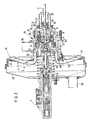
- the left in Fig. 2 provided with a pneumatic connection 55 housing part 48 is fixedly connected to the tandem master cylinder 2, while the right housing part 49 has a central guide piece 50 which keeps a control valve housing 51 of the vacuum brake booster 1 slidably and vacuum-tight.
- the control valve housing 51 has a rear control housing part 52, which extends from the vacuum brake booster 1 in the direction of the brake pedal 12, and a front control housing part 53, which is arranged essentially within the vacuum brake booster 1.
- the interior of the booster housing 10 is divided into a first working chamber 5 and a second working chamber 6 by a movable wall 7 arranged therein, consisting of a diaphragm plate 8 and a rolling diaphragm 9 lying thereon, which, during normal braking, is arranged by means of a valve arrangement 58 arranged in the control valve housing 51 is ventilated.
- the valve arrangement 58 which is known per se, is operated by a piston rod 11 connected valve piston 54 actuated, which transmits the actuating force introduced via the brake pedal 12 via a transmission disk 59, a rubber-elastic reaction disk 60 and a pressure plate 61 to a force output member - push rod 62.
- a return spring 57 is provided, which is clamped between the front housing part 48 and the diaphragm plate 8.
- a flange 80 is fastened to the brake pedal-side housing part 49 of the booster housing 10 by means of screw connections 79 with the interposition of a seal 81 and has a pneumatic connection 56 to which the pneumatic line 43 leading from the second valve arrangement 40 is connected.
- the rear control housing part 52 is preferably provided with an axial extension 64, which is axially guided in a sealed manner in the flange 80 by means of a sealing ring 65.
- the fastening elements 75 for a flange 80 supporting a motor vehicle body wall delimits, with the rear control housing part 52, a pneumatic space 63 which can be ventilated or evacuated depending on the control signals of the central control electronics 33.
- the transmission area between the rear control housing part 52 and its axial extension 64 has radial openings 74.
- the valve arrangement 58 consisting of a first sealing seat 69 formed on the front control housing part 83, a second sealing seat 70 formed on the valve piston 54 and a poppet valve 87 biased in the closing direction by means of a valve spring 68 is actuated directly by means of an intermediate rod 77, the pedal-side end of which has a guide collar 66 which is guided in a bore 78 in the axial extension 64.
- the sealing of the guide collar 66 is ensured by a sealing sleeve 67 sliding on the wall of the bore 78, the piston rod 11, which is coupled to the brake pedal 12, is mounted on the pedal-side end of the intermediate rod 77.
- the poppet valve 87 is guided within the control valve housing 51 by means of a guide element 72 which is supported on the rear control housing part 52 and on which a compression spring 73 is supported, which prestresses the outer edge of the poppet valve 87 in the direction of the front control housing part 53. Finally, a piston return spring 71 is arranged between the valve piston 54 and the front control housing part 53 and determines the response force of the vacuum brake booster 1.
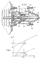
- the control group shown in Fig. 3 differs from that shown in Fig. 2 mainly in that the control valve housing 51 is formed in one piece, the first sealing seat 69 is arranged in the release position of the vacuum brake booster 1 at a distance from the poppet valve 87, which is a free travel of the device.
- the ventilable or evacuable space 63 is outwardly by means of a bellows 82 attached to the flange 86 sealed, whose symmetrically opposite radial fastening region 83 cooperate with the fastening elements 75 in the sense that the fastening elements 75 extend through passage openings 84 formed in the fastening regions 83 in order to be screwed to the body wall during assembly.
- the bellows 82 has at its end facing away from the flange 80 an annular bead 85 which is buttoned in a radial groove 86 formed in the piston rod 11.
- the vacuum brake booster 1 When the brakes are released, that is to say when the vacuum brake booster 1 is not actuated, its two working chambers 5, 6 are evacuated, so that the same pressure conditions prevail in them.
- the working chamber 5 on the master cylinder side is evacuated by means of the vacuum source 42 via the normally open 2/2-way valve 391, while the working chamber 6 on the pedal side is evacuated via the control valve 58.
- the ventilable or evacuable space 63 is acted upon by the atmospheric pressure which is supplied via the pneumatic line 43 and the normally open 2/2-way valve 401.
- the actuation and release of the brakes thus works like a known vacuum brake booster.
- the driver is directly informed of the occurrence of a slip control phase by pulsing the brake pedal.
Landscapes
- Engineering & Computer Science (AREA)
- Transportation (AREA)
- Mechanical Engineering (AREA)
- Physics & Mathematics (AREA)
- Fluid Mechanics (AREA)
- Braking Systems And Boosters (AREA)
- Regulating Braking Force (AREA)
Abstract
Um bei einer blockiergeschützten Kraftfahrzeugbremsanlage eine erhebliche Senkung der erforderlichen Herstellungs- und Montagekosten bei gleichzeitiger Erhöhung deren Betriebssicherheit zu erreichen, wird erfindungsgemäß vorgeschlagen, daß pneumatische Mittel (39,40) vorgesehen sind, die in einem Schlupfregelfall ein Belüften der ersten Arbeitskammer (5) und/oder ein Evakuieren der zweiten Arbeitskammer (6) des Vakuumbremskraftverstärkers (1) ermöglichen, um dessen Verstärkungskraft in einer der Betätigungsrichtung des Hauptbremszylinders (2) entgegengesetzten Richtung wirksam bzw. unwirksam werden zu lassen. 
Description
Die Erfindung betrifft eine Kraftfahrzeugbremsanlage mit einem wirkungsmäßig zwischen Bremspedal und Hauptbremszylinder angeordneten Vakuumbremskraftverstärker mit zumindest zwei durch eine bewegliche Wand voneinander getrennten Arbeitskammern, von denen die erste mit einer Vakuumquelle verbindbar und die zweite über ein mittels einer mit dem Bremspedal gekoppelten Kolbenstange betätigbaren Steuerventil belüftbar ist, um eine zur Bremspedalkraft proportionale Verstärkungskraft zu erzeugen, wobei an einen Primär- und einen Sekundärdruckraum des Hauptbremszylinders über Bremsleitungen Radbremszylinder angeschlossen sind, mit den zu bremsenden Rädern zugeordneten Sensoren, die das Drehverhalten der Räder erfassen, um ein Blockieren festzustellen, und deren Ausgangssignale einer zentralen Regelelektronik zuführbar sind, mit deren Steuersignalen zur Schlupfregelung in die Bremsleitungen eingefügte elektromagnetisch betätigbare Druckmittel- Einlaß- und Auslaßventile steuerbar sind.The invention relates to a motor vehicle brake system with a vacuum brake booster which is operatively arranged between the brake pedal and master brake cylinder and has at least two working chambers separated from one another by a movable wall, the first of which can be connected to a vacuum source and the second can be ventilated via a control valve which can be actuated by means of a piston rod coupled to the brake pedal. in order to generate a reinforcement force proportional to the brake pedal force, wheel brake cylinders being connected to a primary and a secondary pressure chamber of the master brake cylinder via brake lines, with the sensors to be braked, which detect the rotational behavior of the wheels in order to determine a blockage, and their output signals to a central one Control electronics can be supplied, with their control signals for slip control in the brake lines inserted electromagnetically actuated pressure medium inlet and outlet valves can be controlled.
Eine solche Bremsanlage ist z.B. aus der DE-OS 36 27 000 bekannt. Das Besondere an dieser bekannten, mit einem hydraulischen Hilfsdruck-Versorgungssystem arbeitenden Bremsanlage besteht darin, daß, um in einem Schlupfregelfall den vom Hauptbremszylinder erzeugten Bremsdruck schnell abbauen zu können, die Kolben des Hauptbremszy linders mit Zentral-Regel-Ventilen versehen sind, die in der Bremslösestellung Druckmittelverbindungen zwischen einem Druckmittelvorratsbehälter und den Druck- räumen des Hauptbremszylinders öffnen und in der Brems- stellung diese Druckmittelverbindungen schließen, wobei die Bremsleitungen über Einströmleitungen, in die Rückschlag- ventile eingeschaltet sind, mit den motorisch angetriebenen Pumpen des Hilfsdruck-Versorgungssystems in Verbindung stehen, deren Sauganschlüsse über eine Saugleitung an den Druckmittelvorratsbehälter angeschlossen sind.Such a brake system is known for example from DE-OS 36 27 000. The special feature of this known brake system working with a hydraulic auxiliary pressure supply system is that, in order to be able to rapidly reduce the brake pressure generated by the master brake cylinder in a slip control case, the pistons of the master brake cylinder are also provided with central control valves that open pressure medium connections between a pressure medium reservoir and the pressure chambers of the master brake cylinder in the brake release position and close these pressure medium connections in the brake position, the brake lines being switched on via inflow lines into the check valves, are connected to the motor-driven pumps of the auxiliary pressure supply system, the suction connections of which are connected to the pressure medium reservoir via a suction line.
Weniger vorteilhaft anzusehen ist bei der vorbekannten Bremsanlage der beträchtliche Konstruktionsaufwand, der zum Erzeugen und Steuern des hydraulischen Hilfsdruckes, zum Zurückhalten der Hauptbremszylinderkolben sowie zum Sicherstellen der Bremsfunktion beim Ausfall einzelner Bremskreise erforderlich ist.In the known brake system, the considerable design effort required to generate and control the hydraulic auxiliary pressure, to retain the master brake cylinder pistons and to ensure the brake function in the event of failure of individual brake circuits is less advantageous.
Es ist daher Aufgabe der vorliegenden Erfindung, eine Bremsanlage der eingangs genannten Gattung so auszubilden, daß bei gleichzeitiger Erhöhung deren Betriebssicherheit eine erhebliche Senkung der erforderlichen Herstellungs- und Montagekosten erreicht wird. Weiterhin sollen nach jeder Schlupfregelung die Hauptzylinderkolben bzw. das Bremspedal vollständig zurückgestellt werden. Schließlich soll die Bremsanlage ein einfaches Antiblockier-System darstellen.It is therefore an object of the present invention to design a brake system of the type mentioned at the outset in such a way that, while increasing its operational safety, a considerable reduction in the necessary manufacturing and assembly costs is achieved. Furthermore, the master cylinder pistons or the brake pedal should be completely reset after each slip control. Finally, the brake system is supposed to be a simple anti-lock braking system.
Diese Aufgaben werden erfindungsgemäß dadurch gelöst, daß pneumatische Mittel vorgesehen sind, die in einem Schlupfregelfall ein Belüften der ersten Arbeitskammer und/oder ein Evakuieren der zweiten Arbeitskammer ermöglichen, um die Verstärkungskraft des Vakuumbremskraftverstärkers in einer der Betätigungsrichtung des Hauptbremszylinders entgegengesetzten Richtung wirksam oder unwirksam werden-zu lassen.According to the invention, these objects are achieved in that pneumatic means are provided which, in a slip control case, ventilate the first working chamber and / or enable evacuation of the second working chamber in order to make the amplifying force of the vacuum brake booster effective or ineffective in a direction opposite to the actuating direction of the master brake cylinder.
Die pneumatischen Mittel sind bei einer vorteilhaften Weiterbildung des Erfindungsgegenstandes durch je zwei 2/2 Wegeventile gebildet, die durch Steuersignal der zentralen Regelelektronik erregbar sind.In an advantageous development of the subject matter of the invention, the pneumatic means are each formed by two 2/2-way valves which can be excited by a control signal from the central control electronics.
Eine Vereinfachung des Aufbaus der erfindungsgemäßen Kraftfahrzeugbremsanlage wird dadurch erreicht, daß die 2/2-Wegeventile als stromlos offene und stromlos geschlossene Elektromagnetventile ausgebildet sind.A simplification of the structure of the motor vehicle brake system according to the invention is achieved in that the 2/2-way valves are designed as normally open and normally closed solenoid valves.
Um einen herkömmlichen Vakuumbremskraftverstärker bei der erfindungsgemäßen Kraftfahrzeugbremsanlage einsetzen zu können ist nach einem weiteren bevorzugten Merkmal vorgesehen, daß die pneumatischen Mittel an die zweite Arbeitskammer mittels eines am Verstärkergehäuse vorgesehenen Flansches angeschlossen sind, der mit einem pneumatischen Anschluß versehen ist und mit dem Verstärkergehäuse sowie einem Steuerventilgehäuse einen belüftbaren und evakuierbaren Raum begrenzt.In order to be able to use a conventional vacuum brake booster in the motor vehicle brake system according to the invention, it is provided according to a further preferred feature that the pneumatic means are connected to the second working chamber by means of a flange provided on the booster housing, which is provided with a pneumatic connection and with the booster housing and a control valve housing limited a ventilatable and evacuable space.
Eine Erhöhung der Funktionssicherheit kann bei einer vorteilhaften Ausführung des Erfindungsgegenstandes dadurch erreicht werden, daß das Steuerventilgehäuse eine axiale Verlängerung aufweist, die im Flansch abgedichtet geführt ist.In an advantageous embodiment of the subject matter of the invention, functional reliability can be increased in that the control valve housing has an axial extension which is guided in a sealed manner in the flange.
Eine besonders kompakte, kostengünstig herstellbare Weiterbildung des Erfindungsgegenstandes zeichnet sich schließlich dadurch aus, daß der belüftbare bzw. evakuierbare Raum von der Umgebungsatmosphäre durch einen Faltenbalg getrennt wird, der sich zwischen dem Flansch und der Kolbenstange erstreckt.A particularly compact, inexpensive production of the subject of the invention is finally characterized in that the ventilable or evacuable space is separated from the ambient atmosphere by a bellows which extends between the flange and the piston rod.
Weitere Merkmale, Vorteile und Anwendungsmöglichkeiten der Erfindung gehen aus den Unteransprüchen und der folgenden Beschreibung eines Ausführungsbeispiels anhand der beigefügten Zeichnung hervor. In der Zeichnung zeigt:
- Fig. 1 eine schematische Darstellung einer Kraftfahrzeugbremsanlage nach der Erfindung;
- Fig. 2 einen Schnitt durch ein Ausführungsbeispiel eines Vakuumbremskraftverstärkers,
- Fig. 3 eine Teildarstellung einer zweiten Ausführung des erfindungsgemäßen Vakuumbremskraftverstärkers im Axialschnitt und
- Fig. 4 eine diagrammatische Darstellung der Funktion der erfindungsgemäßen Kraftfahrzeugbremsanlage in einem Schlupfregelfall.
- Figure 1 is a schematic representation of a motor vehicle brake system according to the invention.
- 2 shows a section through an embodiment of a vacuum brake booster,
- Fig. 3 is a partial view of a second embodiment of the vacuum brake booster according to the invention in axial section and
- Fig. 4 is a diagrammatic representation of the function of the motor vehicle brake system according to the invention in a slip control case.
In den verschiedenen Figuren der Zeichnung sind einander entsprechende Bauteile mit gleichen Bezugszeichen bezeichnet.Corresponding components in the various figures of the drawing are identified by the same reference numerals.
Fig. 1 zeigt eine Kraftfahrzeugsbremsanlage mit einem Vakuum-Bremskraftverstärker 1, der über eine Kolbenstange 11 in bekannter Weise mit einem Bremspedal 12 verbunden ist. Auf der der Kolbenstange 11 abgewandten Seite des Vakuum-Bremskraftverstärkers 1 ist ein Tandem-Hauptbremszylinder 2 vorgesehen, der mit einem nicht dargestellten Bremsflüssigkeitsbehälter in Verbindung steht. An die Druckräume 80,90 des Tandem-Hauptbremszylinders 2 ist ein erster und ein zweiter Bremskreis 17 bzw. 16 angeschlossen.Fig. 1 shows a motor vehicle brake system with a
Der erste Bremskreis 17 verbindet über zwei Magnetventile 18,19, die als 2/2-Wegeventile ausgebildet sind, die Radbremszylinder der nur schematisch dargestellten zwei Radbremsen 20 bzw. 21 mit dem Tandem-Hauptbremszylinder 2. Jedes der beiden Magnetventile 18,19 ist hierbei einer der beiden Radbremsen 20 bzw. 21 zugeordnet. Der zweite Bremskreis 16 verbindet die Radbremszylinder der ebenfalls nur schematisch dargestellten weiteren zwei Radbremsen 22,23 mit dem Tandem-Hauptbremszylinder 2 über zwei weitere Magnetventile 14,24 die ebenfalls als 2/2-Wegeventile ausgebildet sind.The
Den Vorder- und Hinterradbremsen 20,21,22 und 23 ist jeweils ein Sensor 25,26,27 bzw. 28 zugeordnet, die über ent- sprechende Signalleitungen 29,30,31 bzw. 32 mit einer zentralen Regelelektronik 33 verbunden sind. Die Sensoren 25,26,27 und 28, die beispielsweise als induktive Meßwertaufnehmer ausgebildet sein können, überwachen das Raddrehverhalten und liefern entsprechende Signale über die Signalleitungen 29,30,31 bzw. 32 an die Regelelektronik 33.A
Die Regelelektronik 33 ist über Steuerleitungen 34,35,36,37 mit den Magnetventilen 18,19 bzw. 14,24 verbunden, um diese in Abhängigkeit von den Sensorsignalen zu betätigen.The
An den Vakuumbremskraftverstärker 1 sind über pneumatische Leitungen 38,43 pneumatische Mittel - Ventilanordnungen 39,40 angeschlossen, die in Abhängigkeit von den Steuersignalen der Regelelektronik 33 ein Evakuieren bzw. Belüften näher nicht bezeichneter Arbeitskammern des Vakuumbremskraftverstärkers 1 ermöglichen. Die erste Ventilanordnung 39 wird durch zwei 2/2-Wegeventile 391,392 gebildet, die mittels Steuerleitungen 44,45 mit der Regelelektronik 37 in Verbindung stehen.
Das die Atmosphäre schaltende 2/2-Wegeventil 392 ist vorzugsweise als stromlos geschlossenes Elektromagnetventil ausgebildes, während als das das Vakuum schaltendes 2/2-Wegeventil 391 ein stromlos offenes Elektromagnetventil verwendet wird, dessen Eingang über ein Rückschlagventil 41 an eine Vakuumquelle 42 angeschlossen ist.The atmosphere-switching 2/2-way valve 392 is preferably designed as a normally closed solenoid valve, while as the vacuum-switching 2/2-way valve 391 a normally open electromagnetic valve is used, the input of which is connected to a
An die Vakuumquelle 42 ist auch ein zweites Vakuum schaltenden, stromlos geschlossenes 2/2-Wegeventil 402 der zweiten Ventilanordnung 40 angeschlossen, das über eine dritte Steuerleitung 47 durch die zentrale Regelelektronik 33 erregbar ist. Die zweite Ventilanordnung 40 umfaßt schließlich noch ein zweites, die Atmosphäre schaltendes 2/2-Wegeventil 401, das als stromlos offenes Elektromagnetventil ausgebildet ist und über eine vierte Steuerleitung 46 mit der Regelelektronik 33 verbunden ist.A second vacuum-switching, normally closed 2/2-way valve 402 of the
An eine der beiden Arbeitskammern des Vakuumbremskraftverstärkers 1 ist schließlich ein Drucksensor 15 angeschlossen, dessen Ausgangssignal über eine Signalleitung 13 der zentralen Regelelektronik 33 zugeführt wird.Finally, a
Nach Fig. 2 weist der Vakuumbremskraftverstärker 1 zwei schalenförmige, mit ihren offenen Seiten zusammengebaute Gehäuseteile 48,49 auf, die ein Verstärkergehäuse 10 bilden. Das in Fig. 2 linke mit einem pneumatischen Anschluß 55 versehene Gehäuseteil 48 ist fest mit dem Tandem-Hauptbremszylinder 2 verbunden, während das rechte Gehäuseteil 49 einen zentralen Führungsstutzen 50 aufweist, der ein Steuerventilgehäuse 51 des Vakuum-Bremskraftverstärkers 1 gleitend und vakuumdicht geführt hält. Das Steuerventilgehäuse 51 besitzt ein hinteres Steuergehäuseteil 52, das sich aus dem VakuumBremskraftverstärker 1 in Richtung des Bremspedals 12 hinaus erstreckt, sowie ein vorderes Steuergehäuseteil 53, das im wesentlichen innerhalb des Vakuumbremskraftverstärkers 1 angeordnet ist.2, the
Der Innenraum des Verstärkergehäuses 10 wird durch eine darin angeordnete, aus einem Membranteller 8 und einer daran anliegenden Rollmembran 9 bestehende, bewegliche Wand 7 in eine erste Arbeitskammer 5 sowie eine zweite Arbeitskammer 6 unterteilt, die bei einer Normalbremsung mittels einer im Steuerventilgehäuse 51 angeordneten Ventilanordnung 58 belüftet wird. Die an sich bekannte Ventilanordnung 58 wird von einem mit der Kolbenstange 11 verbundenen Ventilkolben 54 betätigt, der die über das Bremspedal 12 eingeleitete Betätigungskraft über eine Übersetzungsscheibe 59, eine gummielastische Reaktionsscheibe 60 und eine Druckplatte 61 auf ein Kraftabgabeglied - Druckstange 62 - überträgt. Zum Zurückstellen der beweglichen Wand 7 ist eine Rückstellfeder 57 vorgesehen, die zwischen dem vorderen Gehäuseteil 48 und dem Membranteller 8 eingespannt ist.The interior of the
An dem bremspedalseitigen Gehäuseteil 49 des Verstärkergehäuses 10 ist mittels Schraubenverbindungen 79 unter Zwischenschaltung einer Dichtung 81 ein Flansch 80 befestigt, der einen pneumatischen Anschluß 56 aufweist, an den die von der zweiten Ventilanordnung 40 führende pneumatische Leitung 43 angeschlossen ist. Das hintere Steuergehäuseteil 52 ist vorzugsweise mit einer axialen Verlängerung 64 versehen, die im Flansch 80 mittels eines Dichtringes 65 abgedichtet axial geführt ist. Der Befestigungselemente 75 für eine Kraftfahrzeug-Karosseriewand tragende Flansch 80 begrenzt mit dem hinteren Steuergehäuseteil 52 einen pneumatischen Raum 63, der in Abhängigkeit von den Steuersignalen der zentralen Regelelektronik 33 belüftbar bzw. evakuierbar ist.A
Um den Innenraum 76 der an sich bekannten, im Steuerventilgehäuse 51 angeordneten Ventilanordnung 58 mit dem im Raum 63 herrschenden pneumatischen Druck beaufschlagen zu können, weist der Übertragungsbereich zwischen dem hinteren Steuergehäuseteil 52 und dessen axialer Verlängerung 64 radiale Durchbrüche 74 auf.In order to be able to apply the pneumatic pressure prevailing in the
Die aus einem am vorderen Steuergehäuseteil 83 ausgebildeten ersten Dichtsitz 69, einen am Ventilkolben 54 ausgebildeten zweiten Dichtsitz 70 sowie einem in der Schließrichtung mittels einer Ventilfeder 68 vorgespannten Tellerventil 87 bestehende Ventilanordnung 58 wird unmittelbar mittels einer Zwischenstange 77 betätigt, deren pedalseitiges Ende einen Führungsbund 66 aufweist, der in einer Bohrung 78 in der axialen Verlängerung 64 geführt ist. Für die Abdichtung des Führungsbundes 66 sorgt eine an der Wandung der Bohrung 78 gleitende Dichtmanschette 67, die Bohrung mit dem Bremspedal 12 gekoppelte Kolbenstange 11 an dem pedalseitigen Ende der Zwischenstange 77 gelagert ist. Das Tellerventil 87 ist innerhalb des Steuerventilgehäuses 51 mittels eines sich am hinteren Steuergehäuseteil 52 abstützenden Führungselementes 72 geführt, an dem sich eine Druckfeder 73 abstützt, die den Außenrand des Tellerventils 87 in Richtung auf den vorderen Steuergehäuseteil 53 zu vorspannt. Zwischen dem Ventilkolben 54 und dem vorderen Steuergehäuseteil 53 ist schließlich eine Kolbenrückholfeder 71 angeordnet, die die Ansprechkraft des Vakuumbremskraftverstärkers 1 bestimmt.The
Die in Fig. 3 gezeigte Steuergruppe unterscheidet sich von der in Fig. 2 dargestellten vor allem dadurch, daß das Steuerventilgehäuse 51 einteilig ausgebildet ist, wobei der erste Dichtsitz 69 in Lösestellung des Vakuumbremskraftverstärkers 1 in einem Abstand vom Tellerventil 87 angeordnet ist, der als Leerweg des Gerätes bezeichnet wird. Der belüftbare bzw. evakuierbare Raum 63 ist nach außen hin mittels eines am Flansch 86 befestigten Faltenbalges 82 abgedichtet, dessen symmetrisch gegenüberliegend ausgebildete radiale Befestigungsbereich 83 mit den Befestigungselementen 75 in dem Sinne zusammenwirken, daß die Befestigungselemente 75 sich durch in den Befestigungsbereichen 83 ausgebildete Durchtrittsöffnungen 84 hindurch erstrecken, um bei der Montage mit der Karosseriewand verschraubt zu werden. Der Faltenbalg 82 weist an seinem dem Flansch 80 abgewandten Ende einen Ringwulst 85, der in einer in der Kolbenstange 11 ausgebildeten Radialnut 86 eingeknöpft ist.The control group shown in Fig. 3 differs from that shown in Fig. 2 mainly in that the
Die Funktionsweise der in der Zeichnung dargestellten erfindungsgemäßen Kraftfahrzeugbremsanlage wird nachfolgend beschrieben:The mode of operation of the motor vehicle brake system according to the invention shown in the drawing is described below:
Bei gelösten Bremsen, also im unbetätigten Zustand des Vakuumbremskraftverstärkers 1 sind dessen beide Arbeitskammern 5,6 evakuiert, so daß in ihnen die gleichen Druckverhältnisse herrschen. Das Evakuieren der hauptzylinderseitigen Arbeitskammer 5 erfolgt mittels der Vakuumquelle 42 über das stromlos offene 2/2-Wegeventil 391 während das Evakuieren der pedalseitigen Arbeitskammer 6 über das Steuerventil 58 erfolgt. Der belüftbare bzw. evakuierbare Raum 63 wird mit dem Atmosphärendruck beaufschlagt, der ber die pneumatische Leitung 43 und das stromlos offene 2/2-Wegeventil 401 zugeführt wird.When the brakes are released, that is to say when the
Wird nun beim Bremsen das Bremspedal 12 betätigt, so werden durch die Krafteinwirkung die Kolbenstange 11 mit dem Ventilkolben 54 nach links verschoben, wodurch das Steuerventil 58 betätigt wird. Dadurch wird an der beweglichen Wand 7 eine fußkraftproportionale Druckdifferenz einge steuert, die eine Verstärkungskraft erzeugt, die zur Pedalkraft hinzuaddiert und über die Druckstange 62 auf den Primärkolben 81 des Hauptbremszylinders 2 übertragen wird, um einen hydraulischen Druck in den beiden Druckräumen 80 und 90 aufzubauen, der über die Bremskreise 16 und 17 zu den einzelnen Radbremsen 20,21,22 und 23 weitergeleitet wird.If the
Das Betätigen und Lösen der Bremsen funktioniert somit wie bei einem bekannten Vakuumbremskraftverstärker.The actuation and release of the brakes thus works like a known vacuum brake booster.
Wird während eines Bremsvorganges von einem oder mehreren der Sensoren 25,26,27,28 ein Blockieren des zugeordneten Rades festgestellt, so muß der im Hauptbremszylinder 2 aufgebaute Druck zumindest teilweise abgebaut werden. Es wird angenommen, daß die auf das Bremspedal 12 einwirkende Kraft konstant bleibt. Dieser Zustand wird durch den Punkt 2 im Diagramm nach Fig. 4 dargestellt, in dem die Kurve a die darin dargestellte Abhängigkeit ohne, die Kurve b die gleiche Abhängigkeit mit Verstärkungskraft des Vakuumbremskraftverstärkers 1 zeigt. Nach dem der zentralen Regelelektronik 33 von einem der Sensoren die oben erwähnte Blockierneigung gemeldet wurde, erzeugt diese Umschaltsignale, die ein gleichzeitiges Umschalten der beiden 2/2-Wegeventile 391,392 der ersten Ventilanordnung 39 und somit ein Belüften der hauptbremszylinderseitigen Arbeitskammer 5 des Vakuumbremskraftverstärkers 1 bewirken. Da nunmehr auf die bewegliche Wand 7 keine Druckdifferenz einwirkt, (die bremspedalseitige Arbeitskammer 6 steht nach wie vor unter dem Atmosphärendruck) verschwindet auch die dadurch bedingte Verstärkungskraft. Die beschriebene Wegnahme der Verstärkungskraft hat demnach eine Druckreduzierung im Hauptbremszylinder 2 zur Folge (Punkt 1 im Diagramm in Fig. 4.) Nach dem vollständigen Belüften der hauptbremszylinderseitigen Arbeitskammer 5 teilt der Drucksensor 15 der zentralen Regelelektronik 33 mit, daß für einen weiteren Druckabbau lediglich ein Umschalten der zweiten Ventilanordnung 40 zu erfolgen hat.If one or more of the
Soll der Hauptbremszylinderdruck vollständig abgebaut werden (Punkt 3), so erfolgt ein Umschalten der 2/2-Wegeventile 401,402 der zweiten Ventilanordnung 40. Durch Evakuieren des pneumatischen Raumes 63 bzw. der bremspedalseitigen Arbeitskammer 6 entsteht an der beweglichen Wand 7 eine entgegen der am Bremspedal 12 eingeleiteten Fußkraft wirkende Verstärkungskraft, die einem vollständigen Abbau der Ausgangskraft des Vakuumbremskraftverstärkers 1 bzw. des im Hauptbremszylinder 2 herrschenden hydraulischen Druckes bewirkt.If the master brake cylinder pressure is to be completely reduced (point 3), then the 2/2-
Das Auftreten einer Schlupfregelphase wird dem Fahrer durch ein Pulsieren des Bremspedals direkt mitgeteilt.The driver is directly informed of the occurrence of a slip control phase by pulsing the brake pedal.
- 1 Vakuumbremskraftverstärker1 vacuum brake booster
- 2 Hauptbremszylinder2 master brake cylinders
- 33rd
- 44th
- 5 Vakuumkammer5 vacuum chamber
- 6 Arbeitskammer6 working chamber
- 7 bewegliche Wand7 movable wall
- 8 Membranteller8 membrane plates
- 9 Rollmembran9 rolling membrane
- 10 Verstärkergehäuse10 amplifier housings
- 11 Betätigungsstange11 operating rod
- 12 Bremspedal12 brake pedal
- 13 Signalleitung13 signal line
- 14 Magnetventil14 solenoid valve
- 15 Drucksensor15 pressure sensor
- 16 Bremsleitung16 brake line
- 17 Bremsleitung17 brake line
- 18 Magnetventil18 solenoid valve
- 19 Magnetventil19 solenoid valve
- 20 Radbremse20 wheel brake
- 21 Radbremse21 wheel brake
- 22 Radbremse22 wheel brake
- 23 Radbremse23 wheel brake
- 24 Magnetventil24 solenoid valve
- 25 Sensor25 sensor
- 26 Sensor26 sensor
- 27 Sensor27 sensor
- 28 Sensor28 sensor
- 29 Signalleitung29 signal line
- 30 Signalleitung30 signal line
- 31 Signalleitung31 signal line
- 32 Signalleitung32 signal line
- 33 zentrale Regelelektronik33 central control electronics
- 34 Steuerleitung34 control line
- 35 Steuerleitung35 control line
- 36 Steuerleitung36 control line
- 37 Steuerleitung37 control line
- 38 pneumatische Leitung38 pneumatic line
- 39 erste Ventilanordnung39 first valve arrangement
- 40 zweite Ventilanordnung40 second valve arrangement
- 41 Rückschlagventil41 check valve
- 42 Vakuumquelle42 vacuum source
- 43 pneumatische Leitung43 pneumatic line
- 44 Steuerleitung44 control line
- 45 Steuerleitung45 control line
- 46 Steuerleitung46 control line
- 47 Steuerleitung47 control line
- 48 Gehäuseteil48 housing part
- 49 Gehäuseteil49 housing part
- 50 Führungsstutzen50 guide sockets
- 51 Steuergehäuse51 control housing
- 52 Steuergehäuseteil52 control housing part
- 53 Steuergehäuseteil53 Control housing part
- 54 Ventilkolben54 valve pistons
- 55 pneumatischer Anschluß55 pneumatic connection
- 56 pneumatischer Anschluß56 pneumatic connection
- 57 Rückstellfeder57 return spring
- 58 Ventilanordnung58 valve arrangement
- 59 Übersetzungsscheibe59 transmission disc
- 60 Reaktionsscheibe60 reaction disk
- 61 Druckplatte61 pressure plate
- 62 Kraftabgabeglied62 power output link
- 63 Raum63 room
- 64 Verlängerung64 extension
- 65 Dichtring65 sealing ring
- 66 Führungsbund66 leadership association
- 67 Dichtmanschette67 sealing sleeve
- 68 Feder68 spring
- 69 erster Dichtsitz69 first sealing seat
- 70 zweiter Dichtsitz70 second sealing seat
- 71 Druckfeder71 compression spring
- 72 Führungslement72 management elements
- 73 Druckfeder73 compression spring
- 74 Durchbruch74 breakthrough
- 75 Befestigungselement75 fastener
- 76 Innenraum76 interior
- 77 Zwischenstange77 intermediate rod
- 78 Bohrung78 hole
- 79 Schraubverbindung79 screw connection
- 80 Flansch80 flange
- 81 Dichtung81 seal
- 82 Faltenbalg82 bellows
- 83 Befestigungsbereich83 Fastening area
- 84 Durchtrittsöffnung84 passage opening
- 85 Ringwulst85 ring bead
- 86 Radialnut86 radial groove
- 87 Tellerventil87 poppet valve
Claims (16)
Applications Claiming Priority (2)
| Application Number | Priority Date | Filing Date | Title |
|---|---|---|---|
| DE3817785A DE3817785A1 (en) | 1988-05-26 | 1988-05-26 | MOTOR VEHICLE BRAKE SYSTEM |
| DE3817785 | 1988-05-26 |
Publications (3)
| Publication Number | Publication Date |
|---|---|
| EP0343365A2 true EP0343365A2 (en) | 1989-11-29 |
| EP0343365A3 EP0343365A3 (en) | 1990-06-13 |
| EP0343365B1 EP0343365B1 (en) | 1993-01-20 |
Family
ID=6355103
Family Applications (1)
| Application Number | Title | Priority Date | Filing Date |
|---|---|---|---|
| EP89106787A Expired - Lifetime EP0343365B1 (en) | 1988-05-26 | 1989-04-15 | Vehicle brake installation |
Country Status (4)
| Country | Link |
|---|---|
| US (1) | US4966420A (en) |
| EP (1) | EP0343365B1 (en) |
| JP (1) | JPH0220461A (en) |
| DE (2) | DE3817785A1 (en) |
Cited By (6)
| Publication number | Priority date | Publication date | Assignee | Title |
|---|---|---|---|---|
| US5181769A (en) * | 1988-07-01 | 1993-01-26 | Itt Corporation | Automotive vehicle brake unit with anti-locking device |
| WO1994027847A1 (en) * | 1993-05-28 | 1994-12-08 | Allied Signal, Inc. | Control valve actuator for vacuum brake force booster |
| EP0663327A3 (en) * | 1994-01-15 | 1995-11-08 | Daimler Benz Ag | Method for reducing jolts during braking until a motor vehicle stops. |
| EP0706924A1 (en) * | 1994-10-11 | 1996-04-17 | Lucas Industries Public Limited Company | Electronically controlled brake booster and method for operating it |
| AU708569B3 (en) * | 1997-10-30 | 1999-08-05 | Kalam, Professor A. | Induction of power (in motor) from a stationary object (stator) to a rotary object (rotor) with automatic and sensorless speed and position detection |
| WO2009103468A1 (en) * | 2008-02-22 | 2009-08-27 | Lucas Automotive Gmbh | Technology for the electronic brake force distribution in a vehicle brake system equipped with a hydraulic brake servo |
Families Citing this family (12)
| Publication number | Priority date | Publication date | Assignee | Title |
|---|---|---|---|---|
| DE3910285C2 (en) * | 1989-03-30 | 1996-12-19 | Teves Gmbh Alfred | Hydraulic brake system for motor vehicles with a device for regulating the drive slip |
| DE3933636A1 (en) * | 1989-06-13 | 1991-04-11 | Teves Gmbh Alfred | Vehicle vacuum brake booster |
| DE3920766C3 (en) * | 1989-06-24 | 2002-09-19 | Continental Teves Ag & Co Ohg | Vacuum brake booster for a slip-controlled brake system |
| DE3931469A1 (en) * | 1989-09-21 | 1991-04-04 | Teves Gmbh Alfred | Vehicular hydraulic braking system with antilock mode - uses concentrically seated electromagnetic valve to evacuate working chambers and fill vacuum chambers of braking force amplifier |
| DE3943002A1 (en) * | 1989-12-27 | 1991-07-04 | Lucas Ind Plc | VEHICLE BRAKE SYSTEM |
| DE4004065A1 (en) * | 1990-02-10 | 1991-08-14 | Teves Gmbh Alfred | Vehicle anti-locking braking system - has piston position signal for servo device coupled to electronic control unit for magnetic braking regulation valves |
| JPH0680064A (en) * | 1992-07-13 | 1994-03-22 | Sumitomo Electric Ind Ltd | Liquid pressure controller |
| FR2702437B1 (en) * | 1993-03-10 | 1995-04-28 | Alliedsignal Europ Services | Assisted braking device with simplified automatic control. |
| US5484193A (en) * | 1994-10-21 | 1996-01-16 | Kelsey-Hayes | Single channel best effort anti-lock brake system |
| DE19541101A1 (en) * | 1995-11-06 | 1997-05-07 | Teves Gmbh Alfred | Method for operating a pneumatic brake booster |
| US6073535A (en) * | 1998-08-07 | 2000-06-13 | Robert Bosch Corporation | Guard for a valve body of a brake booster |
| US6386648B1 (en) * | 2000-10-27 | 2002-05-14 | Robert Bosch Corporation | Master cylinder and brake booster for a brake system |
Family Cites Families (10)
| Publication number | Priority date | Publication date | Assignee | Title |
|---|---|---|---|---|
| DE1780667A1 (en) * | 1967-04-08 | 1973-07-19 | Teldix Gmbh | ANTI-LOCK CONTROL SYSTEM FOR A PISTON CONTROLLED HYDRAULIC BRAKING SYSTEM |
| US3498682A (en) * | 1967-09-05 | 1970-03-03 | Eaton Yale & Towne | Braking system |
| JPS4820353B1 (en) * | 1968-06-22 | 1973-06-20 | ||
| US3559532A (en) * | 1968-10-23 | 1971-02-02 | Stanley I Macduff | Travel servomotor |
| GB1415192A (en) * | 1972-03-18 | 1975-11-26 | Lucas Industries Ltd | Braking systems for vehicles |
| DE3317629A1 (en) * | 1983-05-14 | 1984-11-15 | Alfred Teves Gmbh, 6000 Frankfurt | METHOD FOR CONTROLLING A SLIP-CONTROLLED BRAKE SYSTEM AND DEVICE FOR IMPLEMENTING THE METHOD |
| DE3428869A1 (en) * | 1984-08-04 | 1986-02-13 | Alfred Teves Gmbh, 6000 Frankfurt | BRAKE-SLIP-CONTROLLED BRAKE SYSTEM |
| DE3627000C2 (en) * | 1986-08-08 | 1998-05-20 | Teves Gmbh Alfred | Brake system with slip control |
| DE3638510C2 (en) * | 1986-11-11 | 1995-04-13 | Teves Gmbh Alfred | Brake system with slip control |
| DE3641105A1 (en) * | 1986-12-02 | 1988-06-16 | Teves Gmbh Alfred | MOTOR VEHICLE BRAKE DEVICE |
-
1988
- 1988-05-26 DE DE3817785A patent/DE3817785A1/en not_active Withdrawn
-
1989
- 1989-04-15 EP EP89106787A patent/EP0343365B1/en not_active Expired - Lifetime
- 1989-04-15 DE DE8989106787T patent/DE58903318D1/en not_active Expired - Fee Related
- 1989-05-15 US US07/351,978 patent/US4966420A/en not_active Expired - Fee Related
- 1989-05-25 JP JP1132536A patent/JPH0220461A/en active Pending
Cited By (7)
| Publication number | Priority date | Publication date | Assignee | Title |
|---|---|---|---|---|
| US5181769A (en) * | 1988-07-01 | 1993-01-26 | Itt Corporation | Automotive vehicle brake unit with anti-locking device |
| WO1994027847A1 (en) * | 1993-05-28 | 1994-12-08 | Allied Signal, Inc. | Control valve actuator for vacuum brake force booster |
| EP0663327A3 (en) * | 1994-01-15 | 1995-11-08 | Daimler Benz Ag | Method for reducing jolts during braking until a motor vehicle stops. |
| EP0706924A1 (en) * | 1994-10-11 | 1996-04-17 | Lucas Industries Public Limited Company | Electronically controlled brake booster and method for operating it |
| AU708569B3 (en) * | 1997-10-30 | 1999-08-05 | Kalam, Professor A. | Induction of power (in motor) from a stationary object (stator) to a rotary object (rotor) with automatic and sensorless speed and position detection |
| WO2009103468A1 (en) * | 2008-02-22 | 2009-08-27 | Lucas Automotive Gmbh | Technology for the electronic brake force distribution in a vehicle brake system equipped with a hydraulic brake servo |
| US8419138B2 (en) | 2008-02-22 | 2013-04-16 | Lucas Automotive Gmbh | Technology for the electronic brake force distribution in a vehicle brake system equipped with a hydraulic brake servo |
Also Published As
| Publication number | Publication date |
|---|---|
| JPH0220461A (en) | 1990-01-24 |
| EP0343365B1 (en) | 1993-01-20 |
| DE3817785A1 (en) | 1989-12-07 |
| US4966420A (en) | 1990-10-30 |
| DE58903318D1 (en) | 1993-03-04 |
| EP0343365A3 (en) | 1990-06-13 |
Similar Documents
| Publication | Publication Date | Title |
|---|---|---|
| DE3920766C2 (en) | Vacuum brake booster for a slip-controlled brake system | |
| EP0343365B1 (en) | Vehicle brake installation | |
| EP0435113B1 (en) | Vehicle brake installation | |
| DE3641105A1 (en) | MOTOR VEHICLE BRAKE DEVICE | |
| WO1994011226A1 (en) | Vacuum power brake | |
| EP1853469A1 (en) | Braking system for motor vehicles | |
| DE3838848A1 (en) | VACUUM BRAKE POWER AMPLIFIER | |
| DE69202921T2 (en) | Pneumatic servo motor. | |
| WO1995011147A1 (en) | Brake system for motor vehicles | |
| DE4024384A1 (en) | BLOCK-PROOF MOTOR VEHICLE BRAKE SYSTEM | |
| DE4028925A1 (en) | Servo for hydraulic brakes - has servo membrane uncoupled from reaction element on master cylinder to isolate brake pedal during ABS | |
| EP0386179B1 (en) | Motor vehicle brake system with anti-skid unit | |
| DE3822260A1 (en) | Motor vehicle antilock brake system | |
| EP1275570B1 (en) | Braking system with electro-pneumatic modulator | |
| DE9202154U1 (en) | Pneumatic brake booster, especially for motor vehicles | |
| EP0360013B1 (en) | Block-proof brake arrangement for motor vehicles | |
| EP3860892B1 (en) | Pressure control ventil arrangement for abs | |
| DE3822261A1 (en) | BRAKE CONTROL UNIT FOR MOTOR VEHICLES | |
| DE4213621A1 (en) | Antilocking protected hydraulic braking system for motor vehicle - has operating unit consisting of braking power intensifier and connected to two circuit main braking cylinder | |
| DE19727654B4 (en) | Hydraulic valve | |
| DE3916640A1 (en) | Motor vehicle brake system with anti-skid unit | |
| DE4123637A1 (en) | Vehicle antilock brake system with vacuum servo - uses valves for controlled venting of servo regulating braking pressure | |
| DE4418584C1 (en) | Piston=type brake booster for vehicle | |
| DE3843159A1 (en) | Motor vehicle antilock brake system | |
| DE3836113A1 (en) | Vacuum brake booster |
Legal Events
| Date | Code | Title | Description |
|---|---|---|---|
| PUAI | Public reference made under article 153(3) epc to a published international application that has entered the european phase |
Free format text: ORIGINAL CODE: 0009012 |
|
| 17P | Request for examination filed |
Effective date: 19890415 |
|
| AK | Designated contracting states |
Kind code of ref document: A2 Designated state(s): DE ES FR GB IT |
|
| PUAL | Search report despatched |
Free format text: ORIGINAL CODE: 0009013 |
|
| AK | Designated contracting states |
Kind code of ref document: A3 Designated state(s): DE ES FR GB IT |
|
| 17Q | First examination report despatched |
Effective date: 19910708 |
|
| ITF | It: translation for a ep patent filed | ||
| GRAA | (expected) grant |
Free format text: ORIGINAL CODE: 0009210 |
|
| AK | Designated contracting states |
Kind code of ref document: B1 Designated state(s): DE ES FR GB IT |
|
| PG25 | Lapsed in a contracting state [announced via postgrant information from national office to epo] |
Ref country code: GB Effective date: 19930120 Ref country code: FR Effective date: 19930120 Ref country code: ES Free format text: THE PATENT HAS BEEN ANNULLED BY A DECISION OF A NATIONAL AUTHORITY Effective date: 19930120 |
|
| REF | Corresponds to: |
Ref document number: 58903318 Country of ref document: DE Date of ref document: 19930304 |
|
| EN | Fr: translation not filed | ||
| GBV | Gb: ep patent (uk) treated as always having been void in accordance with gb section 77(7)/1977 [no translation filed] |
Effective date: 19930120 |
|
| PLBE | No opposition filed within time limit |
Free format text: ORIGINAL CODE: 0009261 |
|
| STAA | Information on the status of an ep patent application or granted ep patent |
Free format text: STATUS: NO OPPOSITION FILED WITHIN TIME LIMIT |
|
| PG25 | Lapsed in a contracting state [announced via postgrant information from national office to epo] |
Ref country code: DE Effective date: 19940101 |
|
| 26N | No opposition filed | ||
| PG25 | Lapsed in a contracting state [announced via postgrant information from national office to epo] |
Ref country code: IT Free format text: LAPSE BECAUSE OF NON-PAYMENT OF DUE FEES;WARNING: LAPSES OF ITALIAN PATENTS WITH EFFECTIVE DATE BEFORE 2007 MAY HAVE OCCURRED AT ANY TIME BEFORE 2007. THE CORRECT EFFECTIVE DATE MAY BE DIFFERENT FROM THE ONE RECORDED. Effective date: 20050415 |