EP0343097B1 - Roller accumulation conveyor - Google Patents
Roller accumulation conveyor Download PDFInfo
- Publication number
- EP0343097B1 EP0343097B1 EP89730105A EP89730105A EP0343097B1 EP 0343097 B1 EP0343097 B1 EP 0343097B1 EP 89730105 A EP89730105 A EP 89730105A EP 89730105 A EP89730105 A EP 89730105A EP 0343097 B1 EP0343097 B1 EP 0343097B1
- Authority
- EP
- European Patent Office
- Prior art keywords
- roller
- switching
- accumulation conveyor
- rollers
- shift
- Prior art date
- Legal status (The legal status is an assumption and is not a legal conclusion. Google has not performed a legal analysis and makes no representation as to the accuracy of the status listed.)
- Expired - Lifetime
Links
Images

Classifications
-
- B—PERFORMING OPERATIONS; TRANSPORTING
- B65—CONVEYING; PACKING; STORING; HANDLING THIN OR FILAMENTARY MATERIAL
- B65G—TRANSPORT OR STORAGE DEVICES, e.g. CONVEYORS FOR LOADING OR TIPPING, SHOP CONVEYOR SYSTEMS OR PNEUMATIC TUBE CONVEYORS
- B65G47/00—Article or material-handling devices associated with conveyors; Methods employing such devices
- B65G47/22—Devices influencing the relative position or the attitude of articles during transit by conveyors
- B65G47/26—Devices influencing the relative position or the attitude of articles during transit by conveyors arranging the articles, e.g. varying spacing between individual articles
- B65G47/261—Accumulating articles
Abstract
Description
Die Erfindung betrifft eine Staurollenbahn nach den Merkmalen des Oberbegriffes des Hauptanspruches.The invention relates to an accumulation roller conveyor according to the features of the preamble of the main claim.
Aus der EP-A-223 441 ist es bekannt, die Schaltleiste der betreffenden Staurollenbahn als zweiarmigen Hebel auszubilden, dessen unterhalb der Tragrollen gelegener Hebelarm ein Schaltelement betätigt, über das letztlich ein Schaltlineal gesteuert wird.From EP-A-223 441 it is known to design the safety edge of the relevant roller conveyor as a two-armed lever, the lever arm located below the idler rollers actuating a switching element, via which a switching ruler is ultimately controlled.
Bei der dort beschriebenen Konstruktion ist jedoch eine Abbremsung jeder Tragrolle nur schwierig zu realisieren. Die Anordnung von Bremshebeln zwischen den Tragrollen führt zu dem Nachteil, daß keine enge Teilung der Tragrollen ausführbar ist; insgesamt läßt sich eine raumsparende Bauweise nicht erreichen.In the construction described there, however, it is difficult to brake each support roller. The arrangement of brake levers between the support rollers leads to the disadvantage that no narrow division of the support rollers can be carried out; overall, a space-saving design cannot be achieved.
Vergleichbare Nachteile weist auch der Sammelförderer nach AT-B-282 473 auf, bei dem die Bewegungssteuerung pneumatisch erfolgt, wobei eine Druckluftquelle mit dem Betätiger verbunden und ein im Normalfall offenes, von einer Abtastvorrichtung bei Batätigung derselben durch einen Fördergegenstand schließbares Ventil zwischen der Druckluftquelle und dem Batätiger angeordnet ist, und weiters eine, eine bestimmte Zeitverzögerung zwischen dem Schließen des Ventils und dem hiervon abhängigen Verschieben des Antriebsgliedes durch die vom Betätiger verursachte Verschwenkung der Verschiebeeinrichtung erzeugende Entlüftungsvorrichtung vorgesehen ist.The collective conveyor according to AT-B-282 473 also has comparable disadvantages, in which the movement is controlled pneumatically, with a compressed air source connected to the actuator and a valve between the compressed air source and which is normally open and can be closed by a scanning device when actuated by a conveyed object the bat actuator is arranged, and further a, a certain time delay between the closing of the valve and the dependent displacement of the drive member is provided by the pivoting of the displacement device caused by the actuator.
Bei einer Staurollenbahn nach der DE-C-35 22 177 werden die Schaltlineale in umständlicher Weise entgegen der Kraft von Federn verschoben und die Schaltrollen werden, nachdem sie von einer Feder angetippt wurden, vom Antriebsgurt verdreht. Diese Art ist aufwendig und wegen des schwierigen Zusammenspiels mit der Feder zum Bewegen des Schaltlineals unzuverlässig.In a accumulating roller conveyor according to DE-C-35 22 177, the switching rulers are moved in a cumbersome manner against the force of springs and the switching rollers are rotated by the drive belt after they have been tapped by a spring. This type is complex and unreliable due to the difficult interaction with the spring for moving the switching ruler.
Aufgabe der Erfindung ist es daher, eine Staurollenbahn der vorgenannten Art zu vereinfachen und funktionssicherer zu gestalten. Diese Aufgabe wird dadurch gelöst, daß die Schaltleiste eines jeden Stauplatzes als zweiarmiger Hebel ausgebildet ist und mit dem unteren Ende ein Schaltelement betätigt, das über eine Logikschaltung ein Stellgerät für das Schaltlineal steuert, das ein Bolzengelenk für einen Hebel der mit dem exzentrischen Lagerring und dem Exzentertragring versehenen Schaltrolle hat. Schaltelemente und Logiksteuerungen für Stellgeräte sind jetzt preiswerte und bewährte Bauelemente.The object of the invention is therefore to simplify a storage roller conveyor of the aforementioned type and to make it more reliable. This object is achieved in that the safety edge of each storage space is designed as a two-armed lever and with the lower end actuates a switching element that controls an actuator for the switching ruler via a logic circuit, which has a pin joint for a lever with the eccentric bearing ring and the Eccentric support ring provided switching roller. Switching elements and logic controls for actuators are now inexpensive and proven components.
Vorzugsweise beträgt der Winkel zwischen dem Hebel der Schaltrolle und deren exzentrischen Lagerring für die Gurtrolle ca. 135 Grad und der Exzentertragring für die Bremsrolle steht gegenüberliegend vor, so daß bei einem ausreichend großen Hub des Schaltlineals und entsprechendem Verdrehen der Schaltrolle durch deren Hebel entweder die Gurtrolle den Antriebsgurt antreibend oder die Bremsrolle den Bremsgurt bremsend gegen die Tragrollen drückt. Das Schaltelement und die Stellgeräte können Druckmittel- oder Elektrogeräte sein, wobei die Stellgeräte einen vorgegebenen Hub haben können. Alle diese genannten Elemente einer Staurollenbahn sind über Steuerleitungen mit einer Logikschaltung verbunden.Preferably, the angle between the lever of the control roller and its eccentric bearing ring for the belt reel is approximately 135 degrees and the eccentric support ring for the brake roller is opposite, so that with a sufficiently large stroke of the switching ruler and corresponding rotation of the control roller by its lever, either the belt reel driving the drive belt or pressing the brake roller braking the brake belt against the idlers. The switching element and the actuating devices can be pressure medium or electrical devices, whereby the actuating devices can have a predetermined stroke. All of the above-mentioned elements of an accumulation roller conveyor are connected to a logic circuit via control lines.
Ein Ausführungsbeispiel der Erfindung ist in den Zeichnungen dergestellt und im folgenden erläutert. Es zeigen:
- Fig. 1 bis 4
- Ausschnitte eins einer Rollenförderbahn in verschiedenen Staupositionen,
- Fig. 5
- Detail A aus
Figur 2 in größerem Maßstab, - Fig. 6
- Detail B aus
Figur 3 in größerem Maßstab, - Fig. 7
- den Schnitt VII-VII durch die
Figur 5, - Fig. 8
- den Schnitt VIII-VIII durch die Figur 1 in größerem Maßstab.
- 1 to 4
- Cutouts of a roller conveyor in different stowage positions,
- Fig. 5
- Detail A from FIG. 2 on a larger scale,
- Fig. 6
- Detail B from FIG. 3 on a larger scale,
- Fig. 7
- the section VII-VII through Figure 5,
- Fig. 8
- the section VIII-VIII through Figure 1 on a larger scale.
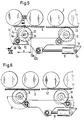
Bei der Lege nach Figur 1 regen alle Schaltleisten 4 über die zwischen Seitenwangen 1 gelagerten Tragrollen 2 hinaus, die auf den Stauplätzen A, B und C von dem Antriebsgurt 3 angetrieben werden. Dieser wird von den Gurtrollen 5 in gehobener Stellung an den Tragrollen 2 entlang geführt. Der Stauplatz A ist der vorderste Stauplatz der Förderbahn und sein Schaltlineal 10A wurde von einem nicht gezeichneten externen Schaltelement in Form eines Ventils oder Endschalters in Vorbereitungsstellung gebracht, d. h., das externe Schaltelement hat in einer pneumatischen oder elektrischen Logikschaltung die Voraussetzung für den zu erfolgenden Stauvorgang geschaffen. Diese Voraussetzung kann auch dadurch zustandekommen, daß an einem dem Stauplatz A vorgelagerten Stauplatz eine Schaltleiste 4 von einem Fördergut verschwenkt wurde. Die Schaltleiste ist als zweiarmiger Hebel ausgebildet und betätigt mit dem unteren Hebelende 4a ein Schaltelement 8. Dieses ist auch über Steuerleitungen 14 an die Logikschaltung 15 nach Figur 2 angeschlossen und bewirkt über ein Stellgerät 9 das Verschieben des Schaltlineals 10 über sein Lagerauge 10a in oder entgegen der Förderrichtung.In the laying according to FIG. 1, all the
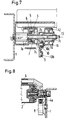
Bei der Schaltsituation nach Figur 2 hat ein Fördergut die Schaltleiste 4 am Stauplatz A heruntergedrückt und damit das Schaltelement 8A geschaltet, wodurch über die Logikschaltung 15 das Steuergerät 9A betätigt wird und einen Hub von ca. 40 mm verrichtet, so daß die Schaltrollen 7 über ihre Hebel 7a um ca. 90 Grad gedreht werden, wie beim Vergleich der Figuren 5 und 6 zu erkennen ist.In the switching situation according to FIG. 2, a conveyed item has pressed the
Bei der Stellung nach den Figuren 5 und 7 sind die Gurtrollen 5 angehoben und der Antriebsgurt 3 liegt von unten an den Tragrollen 2 an. Figur 7 zeigt die Seitenwange 1 mit einer Exzentertragachse 13 für die Schaltrolle 7. Diese hat in der Stellung nach Figur 7 auf dem der Seitenwange 1 zugewandten Ende einen nach oben gerichteten exzentrischen Lagerring 7b für ein Lager 6 der Gurtrolle 5 und auf dem anderen Ende einen vorwiegend nach unten gerichteten Exzentertragring 7c für eine Bremsrolle 11, auf der der Bremsgurt 12 liegt. Da sich die Bremsrolle 11 nur geringfügig gegenüber dem Exzentertragring 7c verdreht, ist kein besonderes Lager für die Bremsrole 11 erforderlich. Aus fertigungstechnischen Gründen ist die Schaltrolle im Bereich des Exzentertragringes 7c aus einem anderen Teil hergestellt als der Bereich des exzentrischen Lagerringes 7b, der mit einem Hebel 7a versehen ist. Dieser ragt mit einem Zapfen 7d durch eine Bohrung 10c des Schaltlineals 10. Dieses hat ein nach unten vorstehendes Lagerauge 10a mit einem Bolzengelenk 10b für den Angriff des Stellgerätes 9, das über eine Achse 9a pendelnd an einer Konsole 1a der Seitenwange 1 befestigt ist.In the position according to FIGS. 5 and 7, the
Wenn ein Fördergut die einer Tragrolle 2 zugeordnete Schaltleiste 4 eines Stauplatzes verschwenkt, betätigt der in Figur 8 erkennbare, nach unten gerichtete Hebel 4a der Schaltleiste 4 ein an der Seitenwange 1 angeordnetes Schaltelement 8. Dieses bewirkt über die Logikschaltung 15 einen Hub e des Stellgerätes 9, das die Schaltleiste 10 in die Stellung nach Figur 6 verschwenkt. Dabei wird die Schaltrolle 7 von dem Hebel 7a um ca. 90 Grad verdreht und die Bremsrolle 11 über den Exzentertragring 7c gehoben, während der exzentrische Lagerring 7b für die Gurtrolle 5 um den Winkel a gesenkt wird, wie in Fig. 6 gezeichnet. Der Antriebsgurt 3 liegt nicht mehr an den Tragrollen 2 an, die dann von dem in axialer Richtung festliegenden Bremsgurt 12 sofort gebremst werden.When a conveyed item pivots the
Bei der Situation nach Figur 3 hat das Fördergut die Schaltleiste 4 des Stauplatzes B betätigt und den Antriebsgurt 3 durch Absenken der Gurtrollen 5 von den Tragrollen 2 gelöst. Das Schaltlineal 10B hat einen Hub e ausgeführt. Die Schaltleiste 4 hat des weiteren über das Schaltelement 8B in der Logikschaltung 15B die Voraussetzung für einen möglichen Stauvorgang am Stauplatz C geschaffen.In the situation according to FIG. 3, the material to be conveyed has actuated the
Bei der Situation nach Figur 4 wurde die Stausituation des Stauplatzes A aufgehoben. Das Schaltlineal 10A wurde durch einen Impuls an einem externen Schaltelement über die Logikschaltung und dem Schaltgerät 9A um den Einschalthub e verschoben.In the situation according to FIG. 4, the stowage situation of stowage location A was eliminated. The switching
Verläßt die Hinterkante des Fördergutes die Schaltleiste 4 am Stauplatz A, so wird das Schaltelement 8A und über die Logikschaltung das Stellgerät 9B betätigt. Somit wird das Schaltlineal 10B um den Einschalthub verschoben, wobei die in den Schaltrollen 7 exzentrisch gelagerten Gurtrollen 5 angehoben werden und den Antriebsgurt 3 gegen die Tragrollen 2 drücken, die das darauf befindliche Fördergut weiterbefördern. Wenn die Hinterkante des Fördergutes die Schaltleiste 4 am Stauplatz B verlassen hat, wird das Schaltelement 8B betätigt und beendet über die Logikschaltung 15 die Vorbereitungsstellung im Stauplatz C.If the rear edge of the material to be conveyed leaves the
Claims (6)
- Roller accumulation conveyor with supporting rollers (2) and shift rods (4) which can be moved into the conveying path to separate a drive belt (3), which is guided by raisable and lowerable belt rollers (5), from the supporting rollers (2), each belt roller (5) being mounted on an eccentric bearing ring (7b) of a shift roller (7) which is mounted on an eccentric supporting shaft (13) and comprises, in addition to the eccentric bearing ring (7b), an eccentric supporting ring (7c), which points towards the opposite side, for a braking roller (11) which, when in the raised position, presses a brake belt (12), which is fixed in the conveying direction, against the supporting rollers (2) from below, and all the shift rollers (7) of an accumulation location being controlled by an axially displaceable linear shift member (10), characterised in that the shift rod (4) is formed as a two-armed lever (4a) and actuates by way of its lower end a switching element (8) which controls an actuating appliance (9) for the linear shift member (10) via a logic circuit (15), which member comprises pin joints (10c) for a lever (7a) which is connected to the shift roller (7).
- Roller accumulation conveyor according to claim 1, characterised in that the actuating appliance (9) is mounted in pendulum fashion about a horizontal axis (9a) at a bracket (1a) of a side wall (1) of the roller accumulation conveyor.
- Roller accumulation conveyor according to claim 2, characterised in that the actuating appliance (9) is a pressure-medium appliance.
- Roller accumulation conveyor according to claim 2, characterised in that the actuating appliance (9) is an electrical appliance.
- Roller accumulation conveyor according to either claim 3 or 4, characterised in that the actuating appliance (9) has a predetermined stroke.
- Roller accumulation conveyor according to one or more of the preceding claims, characterised in that all the switching elements (8) and the actuating appliances (9) of a roller accumulation conveyor are connected via control lines (14) to a logic circuit (15).
Priority Applications (1)
| Application Number | Priority Date | Filing Date | Title |
|---|---|---|---|
| AT89730105T ATE103258T1 (en) | 1988-05-19 | 1989-04-17 | ACCUMULATION ROLLER CONVEYOR. |
Applications Claiming Priority (2)
| Application Number | Priority Date | Filing Date | Title |
|---|---|---|---|
| DE3817388 | 1988-05-19 | ||
| DE3817388A DE3817388C1 (en) | 1988-05-19 | 1988-05-19 |
Publications (3)
| Publication Number | Publication Date |
|---|---|
| EP0343097A2 EP0343097A2 (en) | 1989-11-23 |
| EP0343097A3 EP0343097A3 (en) | 1990-09-12 |
| EP0343097B1 true EP0343097B1 (en) | 1994-03-23 |
Family
ID=6354877
Family Applications (1)
| Application Number | Title | Priority Date | Filing Date |
|---|---|---|---|
| EP89730105A Expired - Lifetime EP0343097B1 (en) | 1988-05-19 | 1989-04-17 | Roller accumulation conveyor |
Country Status (4)
| Country | Link |
|---|---|
| US (1) | US4942957A (en) |
| EP (1) | EP0343097B1 (en) |
| AT (1) | ATE103258T1 (en) |
| DE (2) | DE3817388C1 (en) |
Families Citing this family (15)
| Publication number | Priority date | Publication date | Assignee | Title |
|---|---|---|---|---|
| DE9113989U1 (en) * | 1991-11-11 | 1992-01-16 | Psb Gmbh Foerderanlagen Und Lagertechnik, 6780 Pirmasens, De | |
| DE4409968C2 (en) * | 1994-03-23 | 1997-01-23 | Gebhardt Foerdertech | Kit for braking the idlers of roller conveyors |
| DE4430614A1 (en) * | 1994-08-16 | 1996-02-22 | Mannesmann Ag | Conveyor with holding cells |
| DE4430611A1 (en) | 1994-08-16 | 1996-02-22 | Mannesmann Ag | Device for recognizing conveyed goods on conveyor tracks, in particular of packaged goods in roller conveyors |
| DE4430612A1 (en) * | 1994-08-16 | 1996-02-22 | Mannesmann Ag | Conveyor with holding sections |
| ATE201375T1 (en) | 1996-05-06 | 2001-06-15 | Atecs Mannesmann Ag | ROLLER CONVEYOR WITH CARRYING ROLLERS FOR THE CONVEYED GOODS |
| DE19628711C2 (en) * | 1996-05-06 | 2001-08-02 | Atecs Mannesmann Ag | Accumulation roller conveyor |
| US6065588A (en) * | 1998-07-02 | 2000-05-23 | Mannesmann Dematic Rapistan Corp. | Contact assembly for accumulation conveyors |
| US6193054B1 (en) * | 1998-07-31 | 2001-02-27 | Fki Industries, Inc., Mathews Conveyor Division | Modular accumulator conveyor system |
| US6478142B2 (en) | 1998-12-09 | 2002-11-12 | Rapistan Systems Advertising Corp. | Contact assembly for accumulation conveyors |
| DE10008300A1 (en) * | 2000-02-23 | 2001-08-30 | Schlafhorst Gpt Gmbh Ges Fuer | Transport device for piece goods |
| ITBO20040132A1 (en) * | 2004-03-09 | 2004-06-09 | Dugomrulli Srl | CONVEYOR ROLLER PERFECTED AND RELATED PROCESSING |
| DE102007009444B3 (en) * | 2007-02-23 | 2008-12-04 | Moll Gmbh | Roller conveyor has rollers driven from underneath by endless belt, swiveling arms carrying drive roller at top which is supported by counter-roller mounted beneath it on arm |
| US10081492B1 (en) * | 2018-03-14 | 2018-09-25 | Hytrol Conveyor Company, Inc. | Zoned accumulation conveyor with electrical actuator and associated method |
| CN113666067B (en) * | 2021-08-27 | 2022-10-04 | 江西格仕祺陶瓷有限公司 | Corner transmission equipment that ceramic tile processing used |
Family Cites Families (7)
| Publication number | Priority date | Publication date | Assignee | Title |
|---|---|---|---|---|
| US3420355A (en) * | 1966-10-20 | 1969-01-07 | Rapistan Inc | Accumulator conveyor with pneumatic delay |
| AT282473B (en) * | 1968-03-01 | 1970-06-25 | Rapistan Inc | Collection conveyor with a timer |
| US4609098A (en) * | 1982-03-08 | 1986-09-02 | Figgie International Inc. | Zero pressure accumulating conveyor and module |
| DE3434092C2 (en) * | 1984-09-17 | 1986-10-23 | Mannesmann AG, 4000 Düsseldorf | Accumulation roller conveyor |
| DE3522177C1 (en) * | 1985-06-21 | 1986-12-18 | Mannesmann AG, 4000 Düsseldorf | Line of accumulating rollers |
| US4854445A (en) * | 1985-11-12 | 1989-08-08 | Figgie International Inc. | Wide range accumulator conveyor |
| DE3689624D1 (en) * | 1985-11-12 | 1994-03-17 | Figgie Int Inc | Control circuit for a accumulation conveyor with a wide range of applications. |
-
1988
- 1988-05-19 DE DE3817388A patent/DE3817388C1/de not_active Expired
-
1989
- 1989-04-17 EP EP89730105A patent/EP0343097B1/en not_active Expired - Lifetime
- 1989-04-17 DE DE89730105T patent/DE58907262D1/en not_active Expired - Fee Related
- 1989-04-17 AT AT89730105T patent/ATE103258T1/en not_active IP Right Cessation
- 1989-05-18 US US07/353,742 patent/US4942957A/en not_active Expired - Fee Related
Also Published As
| Publication number | Publication date |
|---|---|
| EP0343097A2 (en) | 1989-11-23 |
| ATE103258T1 (en) | 1994-04-15 |
| EP0343097A3 (en) | 1990-09-12 |
| DE3817388C1 (en) | 1989-07-06 |
| US4942957A (en) | 1990-07-24 |
| DE58907262D1 (en) | 1994-04-28 |
Similar Documents
| Publication | Publication Date | Title |
|---|---|---|
| EP0343097B1 (en) | Roller accumulation conveyor | |
| DE3446805C2 (en) | ||
| EP2737152A1 (en) | Lifting door having a movable door leaf guide | |
| DE3424782C2 (en) | ||
| DE3202382C2 (en) | Reversible accumulation conveyor | |
| DE2151548A1 (en) | Card transport device | |
| DE2635435C2 (en) | Device for centering an endless belt in a machine for drying skins or the like. | |
| EP0049016A1 (en) | Transport mechanism for webs of paper in accounting machines | |
| DE2337875C2 (en) | Suspension device for essentially horizontally displaceable leaves, such as doors, windows or the like | |
| DE3632779C2 (en) | ||
| EP2218666A2 (en) | Pivoting stop for items grouped on a support surface | |
| EP0919473A1 (en) | Device for closing tube-like or bag-like package envelopes | |
| DE19612924A1 (en) | Device for automatically feeding one end of a web of material | |
| DE4206401C2 (en) | Pressing device for one-knife cutting machines | |
| DE509409C (en) | Sorting device for paper sheets or the like consisting of several conveying devices arranged one above the other. | |
| DE2042887B2 (en) | Conveyor device for changing the direction of movement of flat objects by 90 degrees in their plane | |
| EP1010144B1 (en) | Conveying device for individual sheets | |
| AT405047B (en) | DEVICE FOR DIVIDING A PAPER RAIL | |
| WO2019057577A1 (en) | Furnace roller, transport device provided therewith and method for the operation thereof | |
| EP0695715B1 (en) | Device for a sheet delivery apparatus | |
| DE2807118C2 (en) | Barriers for gate entrances, railroad crossings and the like | |
| EP0542097B1 (en) | Accumulating roller conveyor | |
| DE3316256A1 (en) | Safety belt transfer between continuous conveyors of different construction | |
| DE2260718B2 (en) | CURVING BELT CONVEYOR | |
| DE3007731C2 (en) | Device for the transfer of pressed material mats |
Legal Events
| Date | Code | Title | Description |
|---|---|---|---|
| PUAI | Public reference made under article 153(3) epc to a published international application that has entered the european phase |
Free format text: ORIGINAL CODE: 0009012 |
|
| AK | Designated contracting states |
Kind code of ref document: A2 Designated state(s): AT BE CH DE ES FR GB GR IT LI LU NL SE |
|
| PUAL | Search report despatched |
Free format text: ORIGINAL CODE: 0009013 |
|
| RHK1 | Main classification (correction) |
Ipc: B65G 47/26 |
|
| AK | Designated contracting states |
Kind code of ref document: A3 Designated state(s): AT BE CH DE ES FR GB GR IT LI LU NL SE |
|
| 17P | Request for examination filed |
Effective date: 19900816 |
|
| 17Q | First examination report despatched |
Effective date: 19921110 |
|
| GRAA | (expected) grant |
Free format text: ORIGINAL CODE: 0009210 |
|
| AK | Designated contracting states |
Kind code of ref document: B1 Designated state(s): AT BE CH DE ES FR GB GR IT LI LU NL SE |
|
| PG25 | Lapsed in a contracting state [announced via postgrant information from national office to epo] |
Ref country code: IT Free format text: LAPSE BECAUSE OF FAILURE TO SUBMIT A TRANSLATION OF THE DESCRIPTION OR TO PAY THE FEE WITHIN THE PRE;WARNING: LAPSES OF ITALIAN PATENTS WITH EFFECTIVE DATE BEFORE 2007 MAY HAVE OCCURRED AT ANY TIME BEFORE 2007. THE CORRECT EFFECTIVE DATE MAY BE DIFFERENT FROM THE ONE RECORDED.SCRIBED TIME-LIMIT Effective date: 19940323 Ref country code: SE Free format text: THE PATENT HAS BEEN ANNULLED BY A DECISION OF A NATIONAL AUTHORITY Effective date: 19940323 Ref country code: ES Free format text: THE PATENT HAS BEEN ANNULLED BY A DECISION OF A NATIONAL AUTHORITY Effective date: 19940323 Ref country code: BE Effective date: 19940323 Ref country code: GR Free format text: LAPSE BECAUSE OF FAILURE TO SUBMIT A TRANSLATION OF THE DESCRIPTION OR TO PAY THE FEE WITHIN THE PRESCRIBED TIME-LIMIT Effective date: 19940323 |
|
| REF | Corresponds to: |
Ref document number: 103258 Country of ref document: AT Date of ref document: 19940415 Kind code of ref document: T |
|
| ET | Fr: translation filed | ||
| GBT | Gb: translation of ep patent filed (gb section 77(6)(a)/1977) |
Effective date: 19940315 |
|
| PG25 | Lapsed in a contracting state [announced via postgrant information from national office to epo] |
Ref country code: AT Effective date: 19940417 |
|
| REF | Corresponds to: |
Ref document number: 58907262 Country of ref document: DE Date of ref document: 19940428 |
|
| PG25 | Lapsed in a contracting state [announced via postgrant information from national office to epo] |
Ref country code: CH Effective date: 19940430 Ref country code: LI Effective date: 19940430 Ref country code: LU Free format text: LAPSE BECAUSE OF NON-PAYMENT OF DUE FEES Effective date: 19940430 |
|
| REG | Reference to a national code |
Ref country code: CH Ref legal event code: PL |
|
| PLBE | No opposition filed within time limit |
Free format text: ORIGINAL CODE: 0009261 |
|
| STAA | Information on the status of an ep patent application or granted ep patent |
Free format text: STATUS: NO OPPOSITION FILED WITHIN TIME LIMIT |
|
| 26N | No opposition filed | ||
| PGFP | Annual fee paid to national office [announced via postgrant information from national office to epo] |
Ref country code: FR Payment date: 19950320 Year of fee payment: 7 Ref country code: GB Payment date: 19950320 Year of fee payment: 7 |
|
| PG25 | Lapsed in a contracting state [announced via postgrant information from national office to epo] |
Ref country code: GB Effective date: 19960417 |
|
| GBPC | Gb: european patent ceased through non-payment of renewal fee |
Effective date: 19960417 |
|
| PG25 | Lapsed in a contracting state [announced via postgrant information from national office to epo] |
Ref country code: FR Effective date: 19961227 |
|
| REG | Reference to a national code |
Ref country code: FR Ref legal event code: ST |
|
| PGFP | Annual fee paid to national office [announced via postgrant information from national office to epo] |
Ref country code: NL Payment date: 19990329 Year of fee payment: 11 |
|
| PGFP | Annual fee paid to national office [announced via postgrant information from national office to epo] |
Ref country code: DE Payment date: 19990519 Year of fee payment: 11 |
|
| PG25 | Lapsed in a contracting state [announced via postgrant information from national office to epo] |
Ref country code: NL Free format text: LAPSE BECAUSE OF NON-PAYMENT OF DUE FEES Effective date: 20001101 |
|
| NLV4 | Nl: lapsed or anulled due to non-payment of the annual fee |
Effective date: 20001101 |
|
| PG25 | Lapsed in a contracting state [announced via postgrant information from national office to epo] |
Ref country code: DE Free format text: LAPSE BECAUSE OF NON-PAYMENT OF DUE FEES Effective date: 20010201 |