EP0343067B1 - Brechungslinse mit zusammengesetztem Profil - Google Patents
Brechungslinse mit zusammengesetztem Profil Download PDFInfo
- Publication number
- EP0343067B1 EP0343067B1 EP89401361A EP89401361A EP0343067B1 EP 0343067 B1 EP0343067 B1 EP 0343067B1 EP 89401361 A EP89401361 A EP 89401361A EP 89401361 A EP89401361 A EP 89401361A EP 0343067 B1 EP0343067 B1 EP 0343067B1
- Authority
- EP
- European Patent Office
- Prior art keywords
- lens
- lens according
- region
- concentric
- diffractive components
- Prior art date
- Legal status (The legal status is an assumption and is not a legal conclusion. Google has not performed a legal analysis and makes no representation as to the accuracy of the status listed.)
- Expired - Lifetime
Links
- 239000002131 composite material Substances 0.000 title 1
- 230000004438 eyesight Effects 0.000 claims description 35
- 230000003287 optical effect Effects 0.000 claims description 10
- 210000004087 cornea Anatomy 0.000 claims description 3
- 210000000887 face Anatomy 0.000 claims description 3
- 239000007943 implant Substances 0.000 claims description 3
- 210000000695 crystalline len Anatomy 0.000 claims 24
- 238000012937 correction Methods 0.000 description 41
- 208000001491 myopia Diseases 0.000 description 23
- 230000002093 peripheral effect Effects 0.000 description 23
- 230000001179 pupillary effect Effects 0.000 description 20
- 230000006870 function Effects 0.000 description 10
- 238000006073 displacement reaction Methods 0.000 description 4
- 210000000744 eyelid Anatomy 0.000 description 4
- 239000000463 material Substances 0.000 description 4
- 230000007423 decrease Effects 0.000 description 3
- 230000010363 phase shift Effects 0.000 description 3
- 210000001747 pupil Anatomy 0.000 description 3
- 210000001525 retina Anatomy 0.000 description 2
- 230000007704 transition Effects 0.000 description 2
- 206010020675 Hypermetropia Diseases 0.000 description 1
- 208000029091 Refraction disease Diseases 0.000 description 1
- 230000004308 accommodation Effects 0.000 description 1
- 230000004075 alteration Effects 0.000 description 1
- 230000004430 ametropia Effects 0.000 description 1
- 150000001875 compounds Chemical class 0.000 description 1
- 230000007547 defect Effects 0.000 description 1
- 238000005530 etching Methods 0.000 description 1
- 230000004305 hyperopia Effects 0.000 description 1
- 201000006318 hyperopia Diseases 0.000 description 1
- 230000001788 irregular Effects 0.000 description 1
- 238000004519 manufacturing process Methods 0.000 description 1
- 238000000034 method Methods 0.000 description 1
- 238000000465 moulding Methods 0.000 description 1
- 230000004379 myopia Effects 0.000 description 1
- 230000008447 perception Effects 0.000 description 1
- 208000014733 refractive error Diseases 0.000 description 1
- 230000035945 sensitivity Effects 0.000 description 1
- 238000000926 separation method Methods 0.000 description 1
Images



Classifications
-
- G—PHYSICS
- G02—OPTICS
- G02B—OPTICAL ELEMENTS, SYSTEMS OR APPARATUS
- G02B5/00—Optical elements other than lenses
- G02B5/18—Diffraction gratings
- G02B5/1876—Diffractive Fresnel lenses; Zone plates; Kinoforms
- G02B5/189—Structurally combined with optical elements not having diffractive power
- G02B5/1895—Structurally combined with optical elements not having diffractive power such optical elements having dioptric power
-
- G—PHYSICS
- G02—OPTICS
- G02B—OPTICAL ELEMENTS, SYSTEMS OR APPARATUS
- G02B5/00—Optical elements other than lenses
- G02B5/18—Diffraction gratings
- G02B5/1876—Diffractive Fresnel lenses; Zone plates; Kinoforms
-
- G—PHYSICS
- G02—OPTICS
- G02C—SPECTACLES; SUNGLASSES OR GOGGLES INSOFAR AS THEY HAVE THE SAME FEATURES AS SPECTACLES; CONTACT LENSES
- G02C7/00—Optical parts
- G02C7/02—Lenses; Lens systems ; Methods of designing lenses
- G02C7/04—Contact lenses for the eyes
- G02C7/041—Contact lenses for the eyes bifocal; multifocal
- G02C7/042—Simultaneous type
-
- G—PHYSICS
- G02—OPTICS
- G02C—SPECTACLES; SUNGLASSES OR GOGGLES INSOFAR AS THEY HAVE THE SAME FEATURES AS SPECTACLES; CONTACT LENSES
- G02C7/00—Optical parts
- G02C7/02—Lenses; Lens systems ; Methods of designing lenses
- G02C7/04—Contact lenses for the eyes
- G02C7/041—Contact lenses for the eyes bifocal; multifocal
- G02C7/044—Annular configuration, e.g. pupil tuned
-
- G—PHYSICS
- G02—OPTICS
- G02C—SPECTACLES; SUNGLASSES OR GOGGLES INSOFAR AS THEY HAVE THE SAME FEATURES AS SPECTACLES; CONTACT LENSES
- G02C7/00—Optical parts
- G02C7/02—Lenses; Lens systems ; Methods of designing lenses
- G02C7/06—Lenses; Lens systems ; Methods of designing lenses bifocal; multifocal ; progressive
-
- G—PHYSICS
- G02—OPTICS
- G02C—SPECTACLES; SUNGLASSES OR GOGGLES INSOFAR AS THEY HAVE THE SAME FEATURES AS SPECTACLES; CONTACT LENSES
- G02C2202/00—Generic optical aspects applicable to one or more of the subgroups of G02C7/00
- G02C2202/20—Diffractive and Fresnel lenses or lens portions
Definitions
- the present invention relates to the field of ophthalmic lenses.
- the unifocal contact lenses are intended to be placed on the cornea of the eye and they make it possible to compensate for the ametropia of the eye (myopia or hyperopia).
- intraocular implants are intended to replace the lens inside the eye.
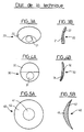
- the document FR-A-1 423 908 evokes, as schematically illustrated in FIGS. 1A and 1B appended corresponding respectively to a front view and to a side section view, a contact lens 10 formed from two regions 11, 12 having on at least one face with radii of different curvatures and therefore of different refractive properties adapted respectively to near vision and to far vision.
- the use of the lens described in document FR-A-1 423 908 requires a relative displacement between the lens and the eye during the transition from far vision to near vision thanks to the support of the lens on the lower eyelid, so that the axis of vision OO passes alternately through one or the other of the two regions 11, 12.
- the theoretical relative position of the lens is illustrated schematically 10 and of the eye respectively in far vision and in near vision.
- a distant object is referenced 13
- a close object is referenced 14
- the retina, the natural lens and the lower eyelid are referenced 15, 16 and 17 respectively.
- Such a type of lens is not entirely satisfactory. It will be noted in particular that this type of lens in theory requires a significant displacement of the lens 10 relative to the eye so that the axis of vision OO passes alternately through one or the other of the two regions 11, 12 Therefore, the essential support of the lens 10 on the lower eyelid 17, combined with the relative displacement of the lens / eye make these lenses difficult to bear. If, moreover, the two types of correction are used simultaneously, the optical axis OO being close to the junction between the two regions 11, 12, an unacceptable image jump is obtained.
- the documents US-A-1 647 721 and US-A-1 735 758 refer to lenses 20, 30, intended to be mounted on spectacle frames which, similarly to document FR-A-1 423 908, regions 21, 22; 31, 32, having different refractive properties; however, according to documents US-A-1 647 721 and US-1 735 758 the different refractive properties are not obtained by variation of radius of curvature, but by variation of index. More precisely, the different refractive properties are obtained by inclusion, in the body 22, 32 of the lens formed of a material of determined index, of an element 21, 31, formed of a material of different index.
- the lenses defined in documents US-A-1 647 721 and US-A-1 735 758 have the same drawbacks as the lens presented in document FR-A-1 423 908.
- the contact lenses of the prior art which have been succinctly described above with reference to FIGS. 1 to 4 are intended to allow alternating vision. These lenses generally require a ballast to maintain their orientation and prevent their rotation on the eye, ballast which constitutes an extra thickness very troublesome for the comfort of the wearer.
- the documents EP-A-1 184 490, EP-A-0 232 191, US-A-4 636 049 evoke a lens contact 40 formed of two concentric regions 41, 42, having on at least one face different radii of curvature and therefore different refractive properties, adapted respectively to near vision and to far vision.
- These lenses no longer require relative movement between the lens and the eye to switch from one type of vision to another.
- the component is very sensitive to variations in the pupillary diameter and the latter may experience large variations depending on the luminance and the patient. For example, if the central region 41 of the lens is assigned to near vision, when the opening of the lens is such that it covers only the central region 41, the user cannot correctly see a distant object.
- Document US-A-3,726,578 mentions a lens which, similarly to documents EP-A-0 184 490, EP-0 232 191 and US-A-4 636 049, concentric regions having different refractive properties.
- the different refractive properties are not obtained by variation of the radius of curvature, but by variation of the index, that is to say by inclusion, in the body of the lens formed of a material of determined index, of an element formed of a material of different index.
- Documents US-A-3,004,470, US-4,162,122, US-A-4,210,391 and US-4,340,283 refer to lenses 50, 60 schematically illustrated in front view in attached FIG. 6A and in side sections in FIGS. 6B and 6C, no longer presenting two concentric regions only as recommended by documents EP-A-0 184 490, EP-0 232 191 and US-A-4 636 049, but a series of concentric zones in a crown 51 , 52; 61, 62, having alternately radii of curvature of a first and a second value 53, 54, 63, 64, to work alternately in near vision and in far vision.
- the documents EP-AO O64 812 and US-A-4 637 697 mention another type of lens, intended to perform a bifocal correction of the eye without zone separation.
- the lens proposed in documents EP-AO O64 812 and US-A-4 637 697 has a posterior surface and an anterior surface of medium curvatures adapted to the correction necessary for the distance vision of the wearer, the lens having in in addition to a hologram which provides the lens with additional diffraction power, such as the image of a close-up object is focused correctly on the retina.
- the hologram can be generated within the lens or on the surface thereof.
- the hologram can be generated by holographic recording.
- the holograms in relief according to the document US-A-4 637 697 are formed of zones 70, 71, 72, 73, 74, concentric of the same surface, that is to say whose external rays evolve according to a geometric progression in K r1 or r1 denotes the external radius of the central zone 70, and K denotes the integers.
- the phase profile of the hologram in relief is identical for all the zones 70, 71, 72, 73, 74 and asymmetrical to favor the +1 diffraction order.
- the phase profile of each zone 70, 71, 72, 73, 74 can be defined by a series of A concentric levels of different thicknesses to obtain differences in optical delay of 2 ⁇ / A.
- the hologram can be provided over all or only part of the optical zone of the lens.
- the lens can be produced with several holograms generated separately, possibly superimposed, providing different diffraction powers.
- obtaining different diffraction powers is materialized by zones consisting of concentric sub-zones whose external rays respond to different geometric progressions from one zone to another .
- the use of lenses of the type mentioned in documents EP-O 064 812 and US-A-4 637 697 poses problems of perception of contrasts under certain vision conditions.
- the document GB-A-802 918 previously described the association, in a sighting system for a firearm, of a part of optical means allowing the user to see clearly a distant target, on the other hand a zoned network allowing the user to observe the handlebars of the weapon.
- the zoned network can be formed either of a transparent lens, one of the faces of which is formed of concentric zones of the same surface, alternately transparent and opaque, or of a transparent lens formed of concentric rings of the same radial surface but alternately having one or the other of two optical thicknesses.
- the object of the present invention is to propose a new type of bifocal or multifocal lens which eliminates the drawbacks of previous lenses.
- the ophthalmic lens according to the present invention is of the known type comprising concentric diffractive components, and it is characterized in that it comprises at least two concentric regions having diffractive components which have phase profiles different from one region to the other to use different diffraction orders.
- the lens according to the present invention because it has diffractive components of different phase profiles distributed over concentric regions, has a diffraction efficiency ratio in far vision and in near vision respectively which evolves according to the diameter of the pupillary opening.
- the lens according to the present invention can therefore be better adapted to the conditions of use.
- a lens 100 in accordance with the present invention comprises at least two concentric regions 110, 120, having diffractive components having different phase profiles in order to favor different diffraction orders.
- the diffractive components can be formed of phase holograms by modulation of the relief or of the index, hereinafter referred to as relief or incide holograms.
- the diffractive concentric regions of the lens 100 according to the present invention can be associated with a refractive component determined by the geometry of the lens.
- the refractive component is formed by the difference in radius of curvature between the two main surfaces 130, 140, of the lens. More specifically, the refractive component may have an identical refractive power over the entire extent of the lens, or may have two different refractive powers, respectively opposite the two concentric regions 110, 120, of diffractive components. It is also possible to envisage using a refractive component having different refractive powers with respect to a single concentric region 110, 120, of diffractive components.
- these diffractive components are formed of index holograms
- these diffractive components are formed of concentric annular zones each having an index variation in the radial direction, the index profile of the various annular zones being identical, for a region considered 110 or 120 but differing from one region to another.
- the external radius of the above-mentioned concentric annular zones evolves according to a geometric progression of the type K r1 where K denotes the integers, and r1 denotes the external radius of the central ring.
- one of the faces 130 or 140 of the lens is formed of concentric annular relief structures.
- Each region 110, 120 is formed of at least one annular structure in relief centered on the axis of the lens.
- Each region 110, 120 can be formed of a large number of concentric relief structures referenced 110a, 110b, 110c ... for the central region 110 and 120a, 120b, 120c ... for the peripheral region 120 in the figures. 8 and 11.
- These structures 110a, 110b; 120a, 120b have the same profile for the same region 110 or 120 but the relief structures 110a, 110b; 120a, 120b, have different profiles from one region to another.
- the different structures 110a, 110b; 120a, 120b all have the same surface.
- the external rays of the different structures evolve according to a geometric progression of the type K r1 where r1 denotes the external radius of the central structure 110a, as illustrated in FIGS. 8 and 11 and K denotes successive integers.
- N1 D12 / 4 r12.
- N2 (D22 - D12) / 4r12.
- N D2 / 4r12.
- the profile of the structures 110a, 110b, 120a, 120b ... can be continuous as illustrated in FIG. 9B; it can also be sampled, as illustrated in FIG. 9A, for example formed by M levels, phase shifted by 2 ⁇ / M generating differences in optical delay ⁇ / M.
- E not Energy in order n Energy incidence
- E not (sin ⁇ n / M) 2 ( ⁇ n / M) 2 sin2 ⁇ (1 - n) M2sin2 ⁇ (1 - n) / M
- the overall diffraction efficiency of a compound diffractive component as illustrated diagrammatically in FIG. 8, of a central region 110 formed of a kinoform sampled in 4 phase-shifted levels of 2 ⁇ / 4 and of a peripheral region 120 formed of a slot function 0, ⁇ as a function of the pupillary opening diameter D is illustrated in FIG. 12.
- the overall efficiency of the lens for the correction + 1 / f decreases towards a asymptote at 0.4 while the overall efficiency of the lens for the correction power -1 / f increases towards an asymptote at 0.4.
- the lens when the diameter D of the pupillary opening is less than or equal to the external diameter D1 of the central region 110, the lens has an overall efficiency identical and equal to 0.4 for the correction powers + 1 / f and -1 / f.
- FIG. 14 shows that the lens conforming to this first example does indeed favor near vision with high luminance while maintaining a correction threshold in near vision with low luminance, on the one hand, and allows far vision with low luminance on the other hand.
- the central and peripheral regions of the refractive component and of the diffractive component are placed respectively opposite, that is to say that they have identical external radii.
- the effectiveness of the lens for near vision, intermediate vision and far vision, as a function of the diameter of the pupillary opening D, is illustrated diagrammatically in FIG. 15. This shows that the lens corresponds to the conditions required, namely a near vision favored in high luminance and an intermediate vision and a far vision favored in low luminance.
- FIG. 16 which schematically illustrates the effectiveness of the lens for the powers of correction in near vision and in far vision shows that the lens conforming to the aforementioned third example meets the expected criteria, namely a near vision maintained at a threshold in high luminance and favored in low luminance and a far vision favored in high luminance.
- the central region and the peripheral region of the refractive component and of the diffractive component are placed respectively opposite, that is to say that they have identical external radii.
- Figure 17 attached which schematically represents the effectiveness of the correction of the lens in near vision, in vision intermediate and far vision shows that the lens according to the fourth example meets the aforementioned criteria, namely: a near vision favored in low luminance as well as an intermediate vision and a far vision favored in high luminance.
- the hologram necessary for the production of the diffractive component having two different phase profiles in accordance with the present invention can be generated using any means known per se to those skilled in the art, in particular by etching, molding or recording. .
Landscapes
- Physics & Mathematics (AREA)
- Health & Medical Sciences (AREA)
- Ophthalmology & Optometry (AREA)
- General Physics & Mathematics (AREA)
- Optics & Photonics (AREA)
- General Health & Medical Sciences (AREA)
- Eyeglasses (AREA)
Claims (15)
- Augenlinse der Bauart mit beugenden, konzentrischen (110a, 110b,...; 120a, 120b...) Bestandteilen, dadurch gekennzeichnet, daß
sie wenigstens zwei konzentrische Bereiche (110, 120) umfaßt, die beugende Bestandteile (110a, 110b,...; 120a, 120b,...) besitzen, die von einem Bereich zum anderen unterschiedliche Phasenprofile aufweisen, um die verschiedenen Ordnungen (h) der Beugung zu nutzen. - Linse nach Anspruch 1, dadurch gekennzeichnet, daß
die beugenden Bestandteile (110a, 110b,...; 120a, 120b...) von reliefförmigen Hologrammen gebildet sind. - Linse nach einem der Ansprüche 1 oder 2, dadurch gekennzeichnet, daß
die beugenden Bestandteile (110a, 110b,...; 120a, 120b...) von ringförmigen, konzentrischen Relief-Strukturen auf einer Seite der Linse gebildet sind, wobei das Profil der verschiedenen Relief-Strukturen für einen betrachteten Bereich identisch, aber von einem Bereich zum anderen verschieden ist. - Linse nach Anspruch 3, dadurch gekennzeichnet, daß
der äußere Radius der Relief-Strukturen (110a, 110b,...; 120a, 120b,...), im Verhältnis zur optischen Achse der Linse sich gemäß einergeometrischen Reihe des Typs
- Linse nach Anspruch 1, dadurch gekennzeichnet, daß
die beugenden Bestandteile von Brechungshologrammen gebildet sind. - Linse nach einem der Ansprüche 1 oder 5, dadurch gekennzeichnet, daß
die beugenden Bestandteile von konzentrischen Ringen gebildet sind, die in radialer Richtung eine Änderung der Brechung aufweisen, wobei das Brechungsprofil der verschiedenen ringförmigen konzentrischen Zonen für einen betrachteten Bereich identisch, aber von einem Bereich zum anderen verschieden ist. - Linse nach Anspruch 6, dadurch gekennzeichnet, daß
der außere Radius der ringförmigen konzentrischen Zonen im Verhältnis zur optischen Achse der Linse sich gemäß einer geometrischen Reihe des Typs
- Linse nach einem der Ansprüche 1 bis 7, dadurch gekennzeichnet, daß
die beugenden Bestandteile mit einem brechenden Bestandteil verbunden sind, der durch die allgemeine Geometrie der Linse (130, 140) gebildet ist. - Linse nach Anspruch 8, dadurch gekennzeichnet, daß
der brechende Bestandteil (130, 140) ein über die ganze Ausdehnung der Linse identisches Brechungsvermögen besitzt. - Linse nach Anspruch 8, dadurch gekennzeichnet, daß
der brechende Bestandteil (130, 140) mindestens zwei verschiedene Brechungsvermögen besitzt, und zwar jeweils bezogen auf die konzentrischen Bereiche der beugenden Bestandteile, die dasselbe Phasenprofil haben. - Linse nach Ansspruch 8, dadurch gekennzeichnet, daß
der brechende Bestandteil (130, 140) mindestens zwei verschiedene Brechungsvermögen besitzt, verglichen mit einem Bereich der beugenden Bestandteile, die dasselbe Phasenprofil haben. - Linse nach einem der Ansprüche 1 bis 11, dadurch gekennzeichnet, daß
die konzentrischen, verschiedene Phasenprofile aufweisenden Bereiche (110, 120) der beugenden Bestandteile zum Arbeiten angepaßt sind, jeweils der eine in der Ordnung n = + 1 und der andere in den Ordnungen n = + 1 und n = - 1. - Linse nach einem der Ansprüche 1 bis 4 und 8 bis 12, dadurch gekennzeichnet, daß
die konzentrischen, verschiedene Phasenprofile aufweisenden Bereiche (110, 120) der beugenden Bestandteile aus jeweils einem in Stufenform, zusammengestellt aus um 2 π/M phasenverschobenen M Niveaus mit M>2 und dem anderen mit Lücken in πn gebildet sind. - Linse nach einem der Ansprüche 1 bis 13, dadurch gekennzeichnet, daß
sie ein intraokulares Implantat bildet, das zum Ersetzen der Augenlinse bestimmt sind. - Linse nach einem der Ansprüche 1 bis 13, dadurch gekennzeichnet, daß
sie eine Kontaktlinse bildet, die zum Aufsetzen auf die Hornhaut des Auges zur Unterstützung der Augenlinse beim Sehen in der Nähe bestimmt ist.
Applications Claiming Priority (2)
| Application Number | Priority Date | Filing Date | Title |
|---|---|---|---|
| FR8806699 | 1988-05-19 | ||
| FR8806699A FR2631713B1 (fr) | 1988-05-19 | 1988-05-19 | Lentille diffractive a profil mixte |
Publications (2)
| Publication Number | Publication Date |
|---|---|
| EP0343067A1 EP0343067A1 (de) | 1989-11-23 |
| EP0343067B1 true EP0343067B1 (de) | 1993-03-31 |
Family
ID=9366429
Family Applications (1)
| Application Number | Title | Priority Date | Filing Date |
|---|---|---|---|
| EP89401361A Expired - Lifetime EP0343067B1 (de) | 1988-05-19 | 1989-05-17 | Brechungslinse mit zusammengesetztem Profil |
Country Status (6)
| Country | Link |
|---|---|
| US (1) | US5114220A (de) |
| EP (1) | EP0343067B1 (de) |
| JP (1) | JPH0219822A (de) |
| AU (1) | AU606519B2 (de) |
| DE (1) | DE68905661T2 (de) |
| FR (1) | FR2631713B1 (de) |
Families Citing this family (77)
| Publication number | Priority date | Publication date | Assignee | Title |
|---|---|---|---|---|
| US5121980A (en) * | 1989-04-19 | 1992-06-16 | Cohen Allen L | Small aperture multifocal |
| AU644126B2 (en) * | 1990-01-08 | 1993-12-02 | Deakin Research Limited | Improvements relating to multi-focal eye lenses having diffractive power |
| GB9008580D0 (en) * | 1990-04-17 | 1990-06-13 | Pilkington Diffractive Lenses | Manufacture of contact lenses |
| US5096285A (en) * | 1990-05-14 | 1992-03-17 | Iolab Corporation | Multifocal multizone diffractive ophthalmic lenses |
| US5178636A (en) * | 1990-05-14 | 1993-01-12 | Iolab Corporation | Tuned fresnel lens for multifocal intraocular applications including small incision surgeries |
| US5229797A (en) * | 1990-08-08 | 1993-07-20 | Minnesota Mining And Manufacturing Company | Multifocal diffractive ophthalmic lenses |
| US5344447A (en) * | 1992-11-12 | 1994-09-06 | Massachusetts Institute Of Technology | Diffractive trifocal intra-ocular lens design |
| US5296880A (en) * | 1992-12-03 | 1994-03-22 | Metro Optics Of Austin, Inc. | Bifocal contact lens |
| US5760871A (en) * | 1993-01-06 | 1998-06-02 | Holo-Or Ltd. | Diffractive multi-focal lens |
| US5748282A (en) * | 1993-01-27 | 1998-05-05 | Pilkington Barnes Hind, Inc. | Multifocal contact lens |
| GB9301614D0 (en) * | 1993-01-27 | 1993-03-17 | Pilkington Diffractive Lenses | Multifocal contact lens |
| US6139146A (en) * | 1997-12-29 | 2000-10-31 | Novartis Ag | Programmable corrective lenses |
| US6473232B2 (en) * | 2000-03-08 | 2002-10-29 | Canon Kabushiki Kaisha | Optical system having a diffractive optical element, and optical apparatus |
| ES2208077B2 (es) * | 2002-05-13 | 2005-05-16 | Universidad De Cantabria | Elemento difractivo multifocal y metodo de fabricacion. |
| US6851803B2 (en) * | 2002-10-24 | 2005-02-08 | C. Benjamin Wooley | Ophthalmic lenses with reduced chromatic blur |
| US7063422B2 (en) * | 2003-04-16 | 2006-06-20 | Novartis Ag | Multifocal ophthalmic lens |
| US6951391B2 (en) * | 2003-06-16 | 2005-10-04 | Apollo Optical Systems Llc | Bifocal multiorder diffractive lenses for vision correction |
| US7044597B2 (en) | 2003-12-16 | 2006-05-16 | Bausch & Lomb Incorporated | Multifocal contact lens and method of manufacture thereof |
| US7061693B2 (en) * | 2004-08-16 | 2006-06-13 | Xceed Imaging Ltd. | Optical method and system for extended depth of focus |
| US7025456B2 (en) * | 2004-08-20 | 2006-04-11 | Apollo Optical Systems, Llc | Diffractive lenses for vision correction |
| US7156516B2 (en) * | 2004-08-20 | 2007-01-02 | Apollo Optical Systems Llc | Diffractive lenses for vision correction |
| AU2013202083B2 (en) * | 2006-02-09 | 2015-03-19 | Alcon Inc. | Pseudo-accomodative iol having diffractive zones with varying areas |
| US7481532B2 (en) * | 2006-02-09 | 2009-01-27 | Alcon, Inc. | Pseudo-accommodative IOL having multiple diffractive patterns |
| US7441894B2 (en) * | 2006-02-09 | 2008-10-28 | Alcon Manufacturing, Ltd. | Pseudo-accommodative IOL having diffractive zones with varying areas |
| US20070258143A1 (en) * | 2006-05-08 | 2007-11-08 | Valdemar Portney | Aspheric multifocal diffractive ophthalmic lens |
| AR062067A1 (es) * | 2006-07-17 | 2008-10-15 | Novartis Ag | Lentes de contacto toricas con perfil de potencia optica controlado |
| US7572007B2 (en) * | 2006-08-02 | 2009-08-11 | Alcon, Inc. | Apodized diffractive IOL with frustrated diffractive region |
| US20080300679A1 (en) * | 2007-06-01 | 2008-12-04 | Altmann Griffith E | Diffractive Intraocular Lens |
| US8747466B2 (en) * | 2007-08-27 | 2014-06-10 | Amo Groningen, B.V. | Intraocular lens having extended depth of focus |
| US8974526B2 (en) * | 2007-08-27 | 2015-03-10 | Amo Groningen B.V. | Multizonal lens with extended depth of focus |
| US8740978B2 (en) * | 2007-08-27 | 2014-06-03 | Amo Regional Holdings | Intraocular lens having extended depth of focus |
| US20090062911A1 (en) * | 2007-08-27 | 2009-03-05 | Amo Groningen Bv | Multizonal lens with extended depth of focus |
| US9216080B2 (en) | 2007-08-27 | 2015-12-22 | Amo Groningen B.V. | Toric lens with decreased sensitivity to cylinder power and rotation and method of using the same |
| CA2715537C (en) | 2008-02-15 | 2016-09-06 | Amo Regional Holdings | System, ophthalmic lens, and method for extending depth of focus |
| US8439498B2 (en) | 2008-02-21 | 2013-05-14 | Abbott Medical Optics Inc. | Toric intraocular lens with modified power characteristics |
| WO2009130610A2 (en) * | 2008-04-24 | 2009-10-29 | Amo Regional Holdings | Diffractive lens exhibiting enhanced optical performance |
| US8231219B2 (en) * | 2008-04-24 | 2012-07-31 | Amo Groningen B.V. | Diffractive lens exhibiting enhanced optical performance |
| US7871162B2 (en) * | 2008-04-24 | 2011-01-18 | Amo Groningen B.V. | Diffractive multifocal lens having radially varying light distribution |
| US8862447B2 (en) | 2010-04-30 | 2014-10-14 | Amo Groningen B.V. | Apparatus, system and method for predictive modeling to design, evaluate and optimize ophthalmic lenses |
| CA2784782C (en) | 2009-12-18 | 2018-02-27 | Hendrik A. Weeber | Limited echelette lens, systems and methods |
| BE1019161A5 (fr) | 2010-01-26 | 2012-04-03 | Physiol | Lentille intraoculaire. |
| US9298019B2 (en) | 2010-05-04 | 2016-03-29 | Johnson & Johnson Vision Care, Inc. | Surface enhanced ophthalmic lens |
| US9817246B2 (en) | 2010-12-01 | 2017-11-14 | Amo Groningen B.V. | Multifocal lens having an optical add power progression, and a system and method of providing same |
| US9931200B2 (en) | 2010-12-17 | 2018-04-03 | Amo Groningen B.V. | Ophthalmic devices, systems, and methods for optimizing peripheral vision |
| US8894204B2 (en) | 2010-12-17 | 2014-11-25 | Abbott Medical Optics Inc. | Ophthalmic lens, systems and methods having at least one rotationally asymmetric diffractive structure |
| BR112015004617A2 (pt) | 2012-08-31 | 2017-07-04 | Amo Groningen Bv | sistemas e métodos para profundidade de foco estendida de lente de múltiplos áneis |
| CN104755997B (zh) * | 2012-10-23 | 2016-11-16 | 埃西勒国际通用光学公司 | 包括多焦点衍射镜片组件的系统 |
| CA2877203A1 (en) | 2012-12-04 | 2014-06-12 | Amo Groningen B.V. | Lenses, systems and methods for providing binocular customized treatments to correct presbyopia |
| AU2014228357B2 (en) | 2013-03-11 | 2018-08-23 | Johnson & Johnson Surgical Vision, Inc. | Intraocular lens that matches an image surface to a retinal shape, and method of designing same |
| WO2016038470A2 (en) | 2014-03-10 | 2016-03-17 | Amo Groningen B.V. | Dual-optic intraocular lens that improves overall vision where there is a local loss of retinal function |
| WO2015177651A1 (en) | 2014-04-21 | 2015-11-26 | Amo Groningen B.V. | Ophthalmic devices, system and methods that improve peripheral vision |
| EP3130314A1 (de) | 2015-08-12 | 2017-02-15 | PhysIOL SA | Trifokale kontaktlinse mit erhöhtem sichtfeld und korrektur von länglicher chromatischer aberration |
| CA3013857A1 (en) | 2016-02-09 | 2017-08-17 | Amo Groningen B.V. | Progressive power intraocular lens, and methods of use and manufacture |
| US11083566B2 (en) | 2016-02-29 | 2021-08-10 | Alcon Inc. | Ophthalmic lens having an extended depth of focus |
| EP3426191B1 (de) | 2016-03-11 | 2024-09-11 | Amo Groningen B.V. | Intraokulare linsen zur verbesserung der peripheren sicht |
| WO2017165623A1 (en) | 2016-03-23 | 2017-09-28 | Abbott Medical Optics Inc. | Power calculator for an ophthalmic apparatus with corrective meridians having extended tolerance or operation band |
| AU2017237090B2 (en) | 2016-03-23 | 2021-10-21 | Johnson & Johnson Surgical Vision, Inc. | Ophthalmic apparatus with corrective meridians having extended tolerance band by modifying refractive powers in uniform meridian distribution |
| US11096778B2 (en) | 2016-04-19 | 2021-08-24 | Amo Groningen B.V. | Ophthalmic devices, system and methods that improve peripheral vision |
| US11013594B2 (en) | 2016-10-25 | 2021-05-25 | Amo Groningen B.V. | Realistic eye models to design and evaluate intraocular lenses for a large field of view |
| US11497599B2 (en) | 2017-03-17 | 2022-11-15 | Amo Groningen B.V. | Diffractive intraocular lenses for extended range of vision |
| US10739227B2 (en) | 2017-03-23 | 2020-08-11 | Johnson & Johnson Surgical Vision, Inc. | Methods and systems for measuring image quality |
| US11523897B2 (en) | 2017-06-23 | 2022-12-13 | Amo Groningen B.V. | Intraocular lenses for presbyopia treatment |
| US11262598B2 (en) | 2017-06-28 | 2022-03-01 | Amo Groningen, B.V. | Diffractive lenses and related intraocular lenses for presbyopia treatment |
| AU2018292030B2 (en) | 2017-06-28 | 2024-02-08 | Amo Groningen B.V. | Extended range and related intraocular lenses for presbyopia treatment |
| US11327210B2 (en) | 2017-06-30 | 2022-05-10 | Amo Groningen B.V. | Non-repeating echelettes and related intraocular lenses for presbyopia treatment |
| CA3082053A1 (en) | 2017-11-30 | 2019-06-06 | Amo Groningen B.V. | Intraocular lenses that improve post-surgical spectacle independent and methods of manufacturing thereof |
| EP3821851A4 (de) | 2018-07-13 | 2022-01-26 | Eyebright Medical Technology (Beijing) Co., Ltd. | Intraokularlinse und herstellungsverfahren dafür |
| US20210278702A1 (en) * | 2018-07-13 | 2021-09-09 | Carl Zeiss Ag | Spectacle lens having a diffraction structure for light |
| US12204178B2 (en) | 2018-12-06 | 2025-01-21 | Amo Groningen B.V. | Diffractive lenses for presbyopia treatment |
| US11886046B2 (en) | 2019-12-30 | 2024-01-30 | Amo Groningen B.V. | Multi-region refractive lenses for vision treatment |
| AU2020416055B2 (en) | 2019-12-30 | 2026-04-30 | Amo Groningen B.V. | Lenses having diffractive profiles with irregular width for vision treatment |
| EP4333685B1 (de) | 2021-05-05 | 2026-01-14 | AMO Groningen B.V. | Ringhalometersystem und verfahren zur quantifizierung von dysphotopsien |
| KR102927446B1 (ko) | 2021-06-14 | 2026-02-13 | 알콘 인코포레이티드 | 다초점 회절성 실리콘 하이드로겔 콘택트렌즈 |
| WO2023099745A1 (en) | 2021-12-03 | 2023-06-08 | Amo Groningen B.V. | Lenses having multi-ring design for vision treatment |
| JP2026506194A (ja) | 2023-02-28 | 2026-02-20 | アルコン インク. | 埋め込み型コンタクトレンズ用のカラーマスク |
| TW202513284A (zh) | 2023-06-01 | 2025-04-01 | 瑞士商愛爾康公司 | 嵌入式水凝膠接觸鏡片 |
| CN121941943A (zh) | 2023-11-20 | 2026-04-28 | 爱尔康公司 | 其中具有高折射率插入物的嵌入式接触镜片 |
Family Cites Families (7)
| Publication number | Priority date | Publication date | Assignee | Title |
|---|---|---|---|---|
| US1735758A (en) * | 1926-06-21 | 1929-11-12 | American Optical Corp | Multifocal lens |
| US1955047A (en) * | 1931-12-03 | 1934-04-17 | Howard D Beach | Spectacle lens |
| US3004470A (en) * | 1956-07-28 | 1961-10-17 | Zeiss Ikon A G Stuttgart | Multiple focal length lens |
| FR1180268A (fr) * | 1956-07-28 | 1959-06-03 | Zeiss Ikon Ag | Lentille à plusieurs foyers |
| US4210391A (en) * | 1977-09-14 | 1980-07-01 | Cohen Allen L | Multifocal zone plate |
| US4162122A (en) * | 1977-09-14 | 1979-07-24 | Cohen Allen L | Zonal bifocal contact lens |
| DE3377535D1 (en) * | 1982-10-27 | 1988-09-01 | Pilkington Plc | Bifocal contact lens comprising a plurality of concentric zones |
-
1988
- 1988-05-19 FR FR8806699A patent/FR2631713B1/fr not_active Expired - Lifetime
-
1989
- 1989-05-10 AU AU34647/89A patent/AU606519B2/en not_active Ceased
- 1989-05-15 US US07/351,968 patent/US5114220A/en not_active Expired - Fee Related
- 1989-05-17 DE DE89401361T patent/DE68905661T2/de not_active Expired - Fee Related
- 1989-05-17 EP EP89401361A patent/EP0343067B1/de not_active Expired - Lifetime
- 1989-05-19 JP JP1124643A patent/JPH0219822A/ja active Pending
Also Published As
| Publication number | Publication date |
|---|---|
| FR2631713A1 (fr) | 1989-11-24 |
| FR2631713B1 (fr) | 1990-08-31 |
| AU606519B2 (en) | 1991-02-07 |
| DE68905661T2 (de) | 1993-10-28 |
| US5114220A (en) | 1992-05-19 |
| EP0343067A1 (de) | 1989-11-23 |
| DE68905661D1 (de) | 1993-05-06 |
| AU3464789A (en) | 1989-11-23 |
| JPH0219822A (ja) | 1990-01-23 |
Similar Documents
| Publication | Publication Date | Title |
|---|---|---|
| EP0343067A1 (de) | Brechungslinse mit zusammengesetztem Profil | |
| EP0382620B1 (de) | Diffraktive ophthalmische Linse für Astigmatismuskorrektur | |
| US7025456B2 (en) | Diffractive lenses for vision correction | |
| EP0611979B1 (de) | Simultanlinse für die Korrektur der Presbyopie und entsprechendes Linsenpaar | |
| EP0990939B1 (de) | Torische ophthalmische Linsen | |
| US4642112A (en) | Artificial eye lenses | |
| AU690410B2 (en) | System incorporating two different sphero-non-spherical contact lenses for correcting presbyopia | |
| US5349394A (en) | Rigid gas permeable lenses | |
| US5100226A (en) | Diffractive ophthalmic lens for correcting astigmatism | |
| US5017000A (en) | Multifocals using phase shifting | |
| CA2764595C (fr) | Realisation d'un verre de lunettes progressif personnalise en fonction d'une perception de flou | |
| EP2350735B1 (de) | Brillenglas mit brillensicht und zusätzlicher sicht | |
| FR2545615A1 (fr) | Lentille ophtalmique multifocale progressive | |
| JPH0158487B2 (de) | ||
| FR2584823A1 (fr) | Lentille multifocale progressive et lunettes employant cette lentille | |
| EP0368751A1 (de) | Strukturierte Diffraktionskontaktlinse | |
| FR2508186A1 (fr) | Lentille ophtalmique a pouvoir progressif | |
| CA2577492A1 (en) | Diffractive lenses for vision correction | |
| CA2536953C (fr) | Systeme optique de compensation accommodative | |
| EP1677707A1 (de) | System zur vergrösserung eines retinabildes | |
| FR2950158A1 (fr) | Verre multifocal permettant a des personnes avec des degres de presbytie differents de l'utiliser. | |
| WO2010142888A1 (fr) | Verre de lunettes adapte pour corriger un defaut oculaire de coma | |
| Loshin | The holographic/diffractive bifocal contact lens | |
| FR3098707A1 (fr) | Implant oculaire diffractif à vision proche élargie | |
| JP2022531469A (ja) | エッジトゥエッジのフォトクロミックソフトコンタクトレンズを設計する方法 |
Legal Events
| Date | Code | Title | Description |
|---|---|---|---|
| PUAI | Public reference made under article 153(3) epc to a published international application that has entered the european phase |
Free format text: ORIGINAL CODE: 0009012 |
|
| AK | Designated contracting states |
Kind code of ref document: A1 Designated state(s): CH DE ES GB IT LI NL SE |
|
| 17P | Request for examination filed |
Effective date: 19900220 |
|
| 17Q | First examination report despatched |
Effective date: 19920221 |
|
| GRAA | (expected) grant |
Free format text: ORIGINAL CODE: 0009210 |
|
| AK | Designated contracting states |
Kind code of ref document: B1 Designated state(s): CH DE ES GB IT LI NL SE |
|
| PG25 | Lapsed in a contracting state [announced via postgrant information from national office to epo] |
Ref country code: IT Free format text: LAPSE BECAUSE OF FAILURE TO SUBMIT A TRANSLATION OF THE DESCRIPTION OR TO PAY THE FEE WITHIN THE PRE;WARNING: LAPSES OF ITALIAN PATENTS WITH EFFECTIVE DATE BEFORE 2007 MAY HAVE OCCURRED AT ANY TIME BEFORE 2007. THE CORRECT EFFECTIVE DATE MAY BE DIFFERENT FROM THE ONE RECORDED.SCRIBED TIME-LIMIT Effective date: 19930331 Ref country code: SE Effective date: 19930331 Ref country code: ES Free format text: THE PATENT HAS BEEN ANNULLED BY A DECISION OF A NATIONAL AUTHORITY Effective date: 19930331 |
|
| REF | Corresponds to: |
Ref document number: 68905661 Country of ref document: DE Date of ref document: 19930506 |
|
| GBT | Gb: translation of ep patent filed (gb section 77(6)(a)/1977) |
Effective date: 19930414 |
|
| PLBE | No opposition filed within time limit |
Free format text: ORIGINAL CODE: 0009261 |
|
| STAA | Information on the status of an ep patent application or granted ep patent |
Free format text: STATUS: NO OPPOSITION FILED WITHIN TIME LIMIT |
|
| 26N | No opposition filed | ||
| PGFP | Annual fee paid to national office [announced via postgrant information from national office to epo] |
Ref country code: NL Payment date: 20010517 Year of fee payment: 13 |
|
| PGFP | Annual fee paid to national office [announced via postgrant information from national office to epo] |
Ref country code: GB Payment date: 20010518 Year of fee payment: 13 |
|
| PGFP | Annual fee paid to national office [announced via postgrant information from national office to epo] |
Ref country code: DE Payment date: 20010613 Year of fee payment: 13 Ref country code: CH Payment date: 20010613 Year of fee payment: 13 |
|
| REG | Reference to a national code |
Ref country code: GB Ref legal event code: IF02 |
|
| PG25 | Lapsed in a contracting state [announced via postgrant information from national office to epo] |
Ref country code: GB Free format text: LAPSE BECAUSE OF NON-PAYMENT OF DUE FEES Effective date: 20020517 |
|
| PG25 | Lapsed in a contracting state [announced via postgrant information from national office to epo] |
Ref country code: CH Free format text: LAPSE BECAUSE OF NON-PAYMENT OF DUE FEES Effective date: 20020531 Ref country code: LI Free format text: LAPSE BECAUSE OF NON-PAYMENT OF DUE FEES Effective date: 20020531 |
|
| PG25 | Lapsed in a contracting state [announced via postgrant information from national office to epo] |
Ref country code: NL Free format text: LAPSE BECAUSE OF NON-PAYMENT OF DUE FEES Effective date: 20021201 |
|
| PG25 | Lapsed in a contracting state [announced via postgrant information from national office to epo] |
Ref country code: DE Free format text: LAPSE BECAUSE OF NON-PAYMENT OF DUE FEES Effective date: 20021203 |
|
| GBPC | Gb: european patent ceased through non-payment of renewal fee |
Effective date: 20020517 |
|
| REG | Reference to a national code |
Ref country code: CH Ref legal event code: PL |
|
| NLV4 | Nl: lapsed or anulled due to non-payment of the annual fee |
Effective date: 20021201 |