EP0342973A2 - Position control system for disk storage drive system - Google Patents
Position control system for disk storage drive system Download PDFInfo
- Publication number
- EP0342973A2 EP0342973A2 EP89305024A EP89305024A EP0342973A2 EP 0342973 A2 EP0342973 A2 EP 0342973A2 EP 89305024 A EP89305024 A EP 89305024A EP 89305024 A EP89305024 A EP 89305024A EP 0342973 A2 EP0342973 A2 EP 0342973A2
- Authority
- EP
- European Patent Office
- Prior art keywords
- signal
- track
- interpolation
- output
- control system
- Prior art date
- Legal status (The legal status is an assumption and is not a legal conclusion. Google has not performed a legal analysis and makes no representation as to the accuracy of the status listed.)
- Granted
Links
Images


Classifications
-
- G—PHYSICS
- G11—INFORMATION STORAGE
- G11B—INFORMATION STORAGE BASED ON RELATIVE MOVEMENT BETWEEN RECORD CARRIER AND TRANSDUCER
- G11B21/00—Head arrangements not specific to the method of recording or reproducing
- G11B21/02—Driving or moving of heads
- G11B21/10—Track finding or aligning by moving the head ; Provisions for maintaining alignment of the head relative to the track during transducing operation, i.e. track following
- G11B21/106—Track finding or aligning by moving the head ; Provisions for maintaining alignment of the head relative to the track during transducing operation, i.e. track following on disks
Definitions
- the present invention relates to a position control system for allowing a data transducer to trace a data track in a disk storage device, and more particularly to a position control system for a disk storage drive system in which a data transducer can be moved to a selected data recording track at a high speed and controlled to keep its relative position to the data recording track.
- the data transducer position control system is desired to be more compact in size and more accurate in operation, which acts as a positioning drive device for allowing the record or playback transducer to trace a reference data track in a magnetic disk storage device or an optical disk storage device.
- the compactification is required for the purpose of increasing the recording capacity in a given size and the high accuracy is also needed for the increase of track density for mass storage.
- the amplitude of track deflection will be about several tens to some dozen tens of micro meters, considerably greater than the width (about 1.6 ⁇ m) of a track to be traced, due to the eccentricity of the center of rotation after replacement of a disk medium and/or the deflection of a rotary shaft of spindle motor for rotation of the disk.
- FDD floppy disk drive
- another kind of track deflection will result from the expansion or shrinkage of a base film of disk medium caused by heatup in addition to the same track deflection as of an optical disk storage device.
- the amplitude of track deflection is rather smaller than in the optical disk storage device. Although the deflection is some dozen to several tens of micro meters in operation, it will not be negligible when the track is reduced in width for mass storage at high density.
- a method in which the deflection of a track is estimated by differentiating 2 times a signal which is the sum of a tracking error signal and an integration signal given by integrating 2 times an input signal to the driver unit for actuating a data transducer for tracking movement.
- the estimation signal corresponding to one rotation of the disk is stored in a memory, it is then read out at a tracking mode and added to the input signal to the driver unit.
- the traceability of the data transducer can be improved, for example, as disclosed by US Patent 4, 594, 622.
- it will be difficult to put this method into practice due to difficulty in suppressing a variation in the integration or a noise resulting from the differentiation.
- a prior art data transducer position control system for disk storage drive system has such a setback as the control of a variation and a noise generated during the estimation of track deflection is too difficult to be executed in practice or as the arithmetic operation of a repeatable error compensation signal is troublesome.
- a position control system for a disk storage drive system which includes a data transducer for record and playback of information stored in a desired data track of an information storage disk having a plurality of data storage tracks thereon, comprises a driver unit for actuating the data transducer in accordance with a reference position command signal, a position encoder for detecting a variation in movement of the data transducer and producing a current position signal representing a current position of the data transducer, a tracking error detector for producing a tracking error signal upon detecting a positional difference of the data transducer from the desired data track, a track deflection estimator for estimating a deflection of track resulting from either eccentricity or undulation of the data track and generating a feed-forward signal on the estimation, and a discrete-time control loop for controlling the driver unit in accordance with the tracking error signal, the loop having a compensating position calculator for calculating a compensating position command signal from the tracking error signal and an inter
- the eccentricity or undulation of a data track is estimated by the track deflection estimator and with its resultant information data, the feed-forward control is then executed, whereby the traceability can be improved in accuracy and consistency.
- the feed-forward signal applied to the driver unit is positively delayed in phase so as to improve the traceability.
- the current position of the driver unit is identified with high accuracy and resolution by the position encoder so that the minimal positioning is possible and the impact from vibration is lessened through increasing the stiffness. As a result, the high density of data tracks can be obtained.
- the interpolation signal is generated by the interpolation calculator through interpolating process of a feed-forward signal and an output from the compensating position calculator and then, added to the reference position command signal, whereby the traceability can be improved.
- Fig. 1 is a block diagram of a position control system for a disk storage drive system according to the present invention.
- the numeral 12 is a driver unit having a function for actuating a data transducer 2 to move about on the disk.
- the driver unit 12 includes an actuator 1 for movement of the data transducer 2, a position encoder 3 connected mechanically with the moving part of the actuator 1 for producing a current position signal ya upon detecting the position of the actuator 1 constantly, a compensator 5, a power supply circuit 4 for energizing the actuator 1 in accordance with an output from the compensator 5, a sample holder 15 for continuous conversion of discrete-time signals ya derived from the position encoder 3, and a comparator 6 for calculating a difference e2 between the reference position command signal rs and the output of the sample holder 15.
- the compensator 5 calculates a control measure of the actuator 1 with reference to the difference e2.
- the position encoder 3 is adapted to detect the action of a moving part constantly and its current position output signal is a linear representation of displacement of the data transducer 2 from a specific reference position within the movable range.
- the compensator 5 is also arranged for following the reference position command signal rs quickly with less error. This servo-loop is substantially an absolute positioning system and thus, will fail to provide the precise tracking along a data track which may deflect as the disk rotates.
- r is a measure of eccentricity or undulation of a selected data track 13 on the disk 14 situated just beneath the data transducer 2, also referred to as a deflection of track, while ys is an absolute position of the data transducer 2.
- a tracking error detector 7 detects a relative position error e1 between the data track 13 and the data transducer 2.
- a compensating position calculator 8 produces a compensating position command signal rd through control calculation with the tracking error e1.
- a track deflection estimator 9 estimates the amplitude of track deflection upon receiving both the tracking error signal e1 and current position signal ya and producing a feed-forward signal rc.
- the compensating position command signal rd and the feed-forward signal rc are then applied to an interpolation calculator 10 where a specific interpolation process is executed.
- the output from the interpolation calculator 10 is a reference position command signal rs.
- the embodiment shown in Fig. 1 employs a tracking servo-system also termed as a sector servo-system or a sampling servo-system.
- the system is adapted in which on the basis of each particular servo information which is essential for tracking and embedded in the border area between fan-shaped sectors formed on the disk, a relative position signal (a tracking error signal) of the data transducer 2 to the target data track is detected in discrete-time base and then, applied in feedback for positioning in a closed loop.
- the system is mainly constituted by a discrete-time control loop for allowing the data transducer 2 to trace the data track 13 with the tracking error signal e1 kept minimum.
- the discrete-time control loop represents a servo-loop from the data transducer 2 via the tracking error detector 7, the compensating position calculator 8, and the interpolation calculator 10 to the driver unit 12. While a deviation of the data transducer 2 from the selected data track 13 varies in time sequence, the position of the data track 13 is identified only intermittently in the sector servo-system and thus, the tracking error signal e1 will be outputted as a discrete-time signal from the tracking error detector 7. The tracking error signal e1 is then processed by specific control calculation in the compensating position calculator 8 to generate the compensating position command signal rd.
- the compensating position calculator 8 has a time discrete processing system containing a deviation compensating factor or if needed, a stability compensating factor and acts primarily for control of the offset.
- the tracking error detector 7 is arranged to detect the relative tracking error signal e1 of the data transducer 2 to the data track 13.
- the position encoder 3 detects the position of the actuator 1 and produces a current position signal ya.
- the absolute position ys of the data transducer 2 is indirectly represented by the current position signal ya, which is expressed as: ys ⁇ ya (2) Therefore, from the statements (1) and (2), the value r is determined by: r ⁇ e1 + ya (3)
- the approximate equation (3) means that the track deflection of a data track can be estimated from the tracking error signal e1 and the current position signal ya.
- the track deflection estimator 9 includes an adder for summing the tracking error signal e1 and the current position signal ya and calculates an estimate of track deflection from the equation (3).
- the resultant estimation rc of a track deflection r is then designated as a feed-forward signal.
- the feed-forward control is a procedure of applying an external signal to the servo-loop, in which the controllability thereof can be increased without reducing the stability when an external signal has been supplied thereto.
- the estimation rc of the track deflection r in the position control system of the present invention is an external signal outside the servo-loop or the discrete-time control loop. More particularly, the input of this signal to the interpolatlon calculator 10 stands for an application to the servo-loop. Accordingly, the stability in the servo-loop remains no doubt unchanged in the event.
- the driver unit 12 cannot respond instantly in practice when the reference position command signal rs is inputted and thus, a delay of time will occur. More specif strictlyically, the transfer properties of the driver unit 12 include a phase delay within the basic and harmonic frequency band of a disk revolution frequency contained primarily in the track deflection r of data track. Also, another phase delay which is derived from a sample hold procedure of the discrete-time control loop, is applied. As a result, the data transducer 2 fails to trace a desired data track with the accuracy of more than a specific degree.
- the track deflection estimator 9 in the position control system for disk storage drive system of the present invention is thus arranged as described below.
- Fig. 2 is a block diagram of the track deflection estimator 9 according to the embodiment of the present invention.
- the track deflection estimator 9 comprises a memory section 21, digital compensators K1, K2, ... Kn-1, and Kn, and an adder 22.
- Z ⁇ 1 is a unit memory for holding an estimation signal of track deflection ra for a time T equal to a sampling period in the discrete-time control loop.
- the memory section 21 is thus constituted for holding the track deflection estimation signals ra corresponding to one rotation of disk by connecting in series n number (n is a positive integer) of unit memories which number corresponds to the number of sectors.
- the output from the final stage of the memory section 21 is connected to the input of the same so that the track deflection estimation signals ra held therein can pass each unit memory recursively as synchronized with the rotation of the disk.
- the memory section 21 may also be formed of shift registers or the like.
- Each of the digital compensators K1, K2, ... Kn-1, and Kn comprises adders and/or multipliers for amplifying or digital filtering the output signal of a unit memory of the memory section 21.
- the adder 22 is arranged to sum up the outputs of the digital compensators for producing the feed-forward signal rc.
- the track deflection estimator 9 of Fig. 2 will be described in principle.
- the track deflection estimation signals ra corresponding to one rotation of the disk are stored in the n number of the unit memories and during tracking, retrieved from their respective unit memories.
- the estimation signals are then applied to their respective digital compensators and summed up by the adder 22 to produce a track deflection estimation signal rc which is equal to or in a bit advance of the actual track deflection r in phase measure.
- the track deflection estimation signal rc is applied to the interpolation calculator 10 together with the output signal rd of the compensating position calculator 8 shown in Fig. 1.
- the actuator 1 moves to eliminate a delay in the tracking motion of the data transducer 2.
- the track deflection estimator 9 may be formed of such a hard ware as described above or a microprocessor containing a software for execution of a similar procedure.
- Fig. 3 is a waveform chart showing the track deflection estimation signal ra of the track deflection estimator of Fig. 2 and respective output signals of the digital compensator Ki and the adder 22.
- the digital compensator Ki is a multiplier for multiplying the signal by 0.1.
- the letter i represents the number of a unit memory as numbered from the front to i-th and is designated as i ⁇ n ⁇ 3/4. While the digital compensators K1 to Kn-1 except Ki are removed, the Kn is an amplifier of gain 1.
- a multiplier 42 multiplies the track deflection estimation signal ra by ⁇ ( ⁇ is a real number and ⁇ ⁇ 1).
- Another multiplier 43 multiplies the output signal rb from the final stage of the memory section 21 by (1 - ⁇ ).
- An adder for 44 adds the outputs of the multipliers 42 and 43.
- the initial setting of a track deflection estimation signal is inputted to the memory section 21 in synchronization with a rotation of the disk while ⁇ is designated as 1 at the first rotation of the disk. If ⁇ is 0.5 at the second rotation of the disk, the track deflection estimation signal ra is multiplied by 0.5 in the multiplier 42 and also, the track deflection estimation signal rb from the memory section 21 is multiplied by 0.5 in the multiplier 43. Then, the outputs from the multipliers 42 and 43 are summed up by the adder 44 and stored again in the memory section 21.
- the coefficient in the multiplier 43 is 1 - ⁇ while the same in the multiplier 42 is ⁇ , so that the signals stored in the memory section 21 can be constantly normalized in amplitude.
- This track deflection estimating procedure features in which the track deflection estimation signal ra stored in the memory section 21 at a particular moment of time, will decrease at a specific rate of 0.25 times the original amount in the second rotation and 0.125 times in the third rotation as the time passes. Accordingly, the remaining percentage of estimation signals which were stored in the past rotation in the memory section 21 will increase as the value of ⁇ becomes close to zero.
- a primary object of the estimation procedure according to the present invention is to smooth amplitude variations of the track deflection estimation signal and level random noise factors contained in the same through repeating the above mentioned operation.
- the track deflection estimator may be formed of such a hard ware as described or a microprocessor having a software for execution of a similar procedure.
- the estimation is effected with the data transducer 2 kept movable for tracing a given track. More specifically, the track deflection estimation procedure of Fig. 4 is carried out with the discrete-time control loop 11 kept activated in the arrangement of Fig. 1.
- the estimation is carried out with the discrete-time control loop 11 kept unactivated in the arrangement of Fig. 1 while the absolute position of the data transducer 2 remains unchanged by applying a specified instruction to the drive unit 12.
- the tracking error detector 7 produces a corresponding signal to the track deflection and the output of the position encoder 3 is a direct current.
- the estimation is carried out with the data transducer 2 either kept movable for tracing an unspecified track or kept fast adjacent to the track.
- the track deflection estimation is carried out intermediate the track seek operations. More specifically, the estimation procedure is carried out for a period of time with the data transducer 2 kept movable for tracing an unspecified track or fixed adjacent to the track and after shifting to another track, the same procedure will be repeated again.
- the timing of the track deflection estimation will then be described.
- Such a procedure as the track deflection estimation is repeated at each of the plural tracks can be employed when the track deflection is constant regardless of the diameter of the disk. Accordingly, the procedure will be inapplicable if the disk, e.g. a floppy disk, has elliptical eccentricity due to changes in the temperature or the moisture. This is because each floppy disk is distinct in elliptical eccentricity as depending on the diameter of a track and also, the writing and reading of data involves frequent seek operations throughout the tracks having respective diameters. Hence, the estimation has to be carried out at each particular data track and within a specific period of time.
- the spindle motor will stop when the access to a disk is interrupted for a certain period of time and the track deflection estimation should thus be carried out intermittently between access operations.
- the track deflection estimation requires at least a duration corresponding to one rotation of the disk and more particularly, a smoothing period taken for improved estimation with less noise while the disk is rotated 2 or 3 more times along a desired track.
- the track deflection estimation is preferably carried out just after the spindle motor starts rotating with the disk loaded in the floppy disk drive system and before the spindle motor stops. If the track deflection is varied during a considerable length of time when the spindle remains ceased, the estimation can be carried out when it is detected that the ceasing period between stop and restart of the spindle exceeds a predetermined time.
- Fig. 5 is a block diagram showing the position control system for disk storage drive system of the present invention in the track seek mode.
- the driver unit 12 acts as a main operator in the track seek mode.
- a track seek instruction rk and an output rc from the track deflection estimator 9 are applied to an adder 51 which in turn sends its output to the driver unit 12.
- the memory section 21 (not shown) in the track deflection estimator 9 is formed in the same recursive arrangement as of Fig. 2 and its final stage output is supplied outwardly through no digital compensator.
- the driver unit 12 is actuated according to the output signal of the adder 51.
- the track seek instruction rk as a position signal is entered without any output of the track deflection estimator 9 applied to the adder 51, the data transducer 2 moves from a track to another track in response to the instruction.
- the output rc of the track deflection estimator 9 is applied to the adder 51 together with the track seek instruction rk thus to correct the deflection of the target track caused after the track seeking.
- Fig. 1 employs a sector servo-system for which a trade-off of design is established in respect of the number of sectors.
- the number of sectors is great, the sampling frequency in discrete-time control system increases and will be available in a wide band for the control.
- a servo-area portion of the recording surface of the disk increases in size and the capacity of storage will be reduced when the formatting on the disk is completed.
- the number of the sectors should be kept minimum to increase the availability on the disk recording surface.
- the sampling frequency in control system decreases and will be available only in a narrow band. This allows the traceability to be increased with much difficulty.
- the controllable range is commonly adjusted so as to equal several to ten times the basic frequency of the track deflection, a control gain on the discrete-time compensator can be increased for control of the track deflection.
- the control gain will hardly increase.
- the number of the sectors is small, the length of a sampling interval will increase while a certain command signal only is applied to the actuator for drive of the data transducer. As the track changes position continuously due to track deflection, an off-track will result from a considerable degree of track deflection even if the control gain is increased.
- Fig. 6 is a block diagram of the interpolation calculator 10 in the embodiment of the present invention, in which represented by 61 is an adder for combining the compensating position command signal rd with the feed-foward signal rc, 62 is an interpolator for performing numerical interpolation upon receiving an output w from the adder 61, and 63 is a sample holder for converting a discrete-time signal v of the interpolator 62 into a continuation.
- the hold time Th of the sample holder 63 is expressed as: Th ⁇ T (12)
- the interpolation is an arithmetic operation in which if values of a function f(x) at m points x1, x2, ... and xm are known, a value of f(x) at a point x is obtained from the known values of f(x). More precisely, termed as interpolation is when the value of x is between the minimum and maximum of the values of m points, but otherwise referred to as extrapolation. Lagrange's interpolation is one of the known similar procedures.
- interpolator 62 The function and operation of the interpolator 62 will specifically be described in reference to a simple example in which m is 2, that is to say, interpola-tion or extrapolation is made with the use of a couple of factors.
- interpolation the relative procedure is not distinguished between interpolation and extrapolation and will be referred to as "interpolation" hereinafter.
- Fig. 7 is a waveform chart of signals showing the track deflection r with no interpolation procedure carried out, the output w from the adder 61, the reference position command signal rs, the absolute position ys of the data transducer, and the real tracking error es incorporated in the position control system for disk storage drive system of the present invention shown in Figs. 1 and 6.
- Fig. 7 Represented by (b) in Fig. 7 is a discrete-time signal designated on the abscissa axis kT (k is a positive integer) at sampling intervals of T.
- the reference position command signal rs which is given by sample holding the output w of the adder 61, is expressed in a wide step waveform.
- the data transducer position ys or a response of the driver unit 12 to the signal rs is also shown in a wide step waveform. Accordingly, the real tracking error es has an oscillatory waveform of great amplitude.
- Fig. 8 is a block diagram showing a substantial arrangement of the interpolator for execution of a first interpolation procedure, in which 81 is a sampler for sampling at intervals of period T/m the input signal w which has been sampled at T period intervals while 82 is a digital filter H(z) provided in the form of an integral filter for smoothing an input signal. Both the sampler 81 and the digital filter 82 are actuated according to an interpolation pulse of T/m period.
- Represented by 83 and 84 are multipliers for multiplying the signal by a numeral a (a is a positive real number and a ⁇ 1) and by 1 - a respectively.
- Z ⁇ 1 is a register for holding data for the sampling period of T/m.
- the interpolator may be formed of a hard ware as described or a microprocessor having a software for execution of a similar procedure.
- a sample signal denoted by the black dot is the input w (kT) uninterpolated.
- An interpolated signal is represented by the white dot.
- the sample signal w (k ⁇ T/m) is then applied to the digital filter 82 which actuates in reference to the T/m period interpolation pulse.
- the signal v smoothed by the digital filter 82 is held by the sampler holder 63 of Fig. 6 for output of a signal rs which has a small step waveform as compared with the signal rs of Fig. 7(c).
- the real tracking error es will be small in the amplitude and moderate in the waveform.
- the output es will be smooth in the response and further smaller in the amplitude.
- the output w from the discrete-time compensator is sampled to a considerable degree and passed through a digital integral filter, whereby the track traceability can be improved.
- Fig. 10 is a block diagram showing another arrangement of the interpolator for execution of a second interpolation procedure, in which 101 is a register actuated on synchronizing with a sector detection pulse for holding the input signal w for a period of T.
- 101 is a register actuated on synchronizing with a sector detection pulse for holding the input signal w for a period of T.
- 102 is an adder for calculating a difference between the current input w(kT) and the register output w((k-1)T).
- 104 is another adder actuated in response to an interpolation pulse for summing up the current input w(kT) and the output of the multiplier 103.
- the interpolator may be formed of a hard ware as described or a microprocessor having a software for execution of a similar procedure.
- Fig. 11 is a waveform chart of signals interpolated by the second interpolation procedure.
- a sample signal denoted by the black dot is the input w(kT) uninterpolated.
- the interpolation is carried out in which the signal values (represented by the white dots) are given by dividing the extension (represented by the broken line) which extends across the summit of the current sample signal w(kT) through the summit of the preceding sample signal w((k-1)T), by the number of m in the following sample period.
- the interpolated output v (represented by both the black dots and the white dots) is held by the sample holder 63 of Fig. 6 for output of a signal rs, as shown in (c) of Fig. 11 where the hatching area represents the result of interpolation.
- the signal rs has a small step waveform as compared with that of Fig. 7[c) and thus, the response ys of the driver unit 12 becomes moderate in the waveform as compared with that of Fig. 7(d). Consequently, the real tracking error es will be small in the amplitude and moderate in the waveform.
- the output es will be smooth in the response and further smaller in the amplitude. The track traceability can thus be improved by interpolation of the signal w.
- a further arrangement of the interpolator will be described, in which the discrete-time signal w is preliminarily held through learning or in reference to a repeatable period for the purpose of an arithmetic operation of interpolation which is then carried out in the first and second interpolation procedures with either the current discrete-time output w or a discrete-time output produced before several sample periods.
- Fig. 12 is a block diagram showing the substantial arrangement of the interpolator for execution of a third interpolation procedure, in which 121 is a memory section actuated in synchronizing with a sector detection pulse for holding a signal w corresponding to one rotation of the disk.
- 121 is a memory section actuated in synchronizing with a sector detection pulse for holding a signal w corresponding to one rotation of the disk.
- 122 is an adder for calculating a difference between the output x(kT) and the output x((k+1)T).
- the interpolator may be formed of a hard ware as described or a microprocessor having a software for execution of a similar procedure.
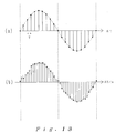
- Fig. 13 is waveform chart of signals interpolated by the third interpolation procedure. Shown in (a) of Fig. 13 is a discrete-time signal put into the memory section 121 through learning or in reference to a repeatable period. As shown in (b) of Fig. 13, a sample signal denoted by the black dot is the time-discrete signal w(kT) applied to the interpolator in a real time.
- the interpolation according to the sample signal stored in the memory section 121 is carried out in which a sloping portion (represented by the broken line) between the current sampling time and the following sampling time is obtained from the sample signal stored in the memory section 121 and is used for interpolation of the following sample period (represented by the white dot). This procedure is made on each sample input for interpolation in correspondence to one rotation of the disk.
- the interpolated signal v is then held by the sample holder 63 of Fig. 6 for output of a signal rs.
- the signal rs is applied to the driver unit 12 and thus, the track traceability can thus be improved as well as in the first or second interpolation procedure.
- Fig. 14(a) is a block diagram of the compensating position calculator 8 in the embodiment of the present invention, in which represented by Z ⁇ 1 is a unit memory for holding a discrete-time signal of sample time T, Ha(z) is a low-band compensation digital filter, Hb(z) is a recursive digital filter, and LPF is a low-pass filter contained within the recursive digital filter for stabilization. There is also provided multipliers L1, L2, ... and L4 for multiplying the input signal by a coefficient.
- Fig. 14(b) shows the frequency characteristics of a transfer function from the tracking error e1 to the compensating position command signal rd. While f0 is a rotation frequency of the disk, a high gain is apparently given in the harmonic frequency component which is a multiplication of the basic frequency f0 by an integer.
- the arrangement of the compensating position calculator is not limited to the above mentioned system and may be formed of a low-band compensator capable of substantially increasing the gain of a low frequency component included in the tracking error signal.
Landscapes
- Moving Of The Head To Find And Align With The Track (AREA)
Abstract
Description
- The present invention relates to a position control system for allowing a data transducer to trace a data track in a disk storage device, and more particularly to a position control system for a disk storage drive system in which a data transducer can be moved to a selected data recording track at a high speed and controlled to keep its relative position to the data recording track.
- As information record/playback apparatuses have remarkably been improved in performance recently, the data transducer position control system is desired to be more compact in size and more accurate in operation, which acts as a positioning drive device for allowing the record or playback transducer to trace a reference data track in a magnetic disk storage device or an optical disk storage device. The compactification is required for the purpose of increasing the recording capacity in a given size and the high accuracy is also needed for the increase of track density for mass storage.
- Deflection of a data track which occurs during tracking, will be described. In an optical disk storage device, the amplitude of track deflection will be about several tens to some dozen tens of micro meters, considerably greater than the width (about 1.6 µm) of a track to be traced, due to the eccentricity of the center of rotation after replacement of a disk medium and/or the deflection of a rotary shaft of spindle motor for rotation of the disk. In a floppy disk drive (FDD), another kind of track deflection will result from the expansion or shrinkage of a base film of disk medium caused by heatup in addition to the same track deflection as of an optical disk storage device. In this case, the amplitude of track deflection is rather smaller than in the optical disk storage device. Although the deflection is some dozen to several tens of micro meters in operation, it will not be negligible when the track is reduced in width for mass storage at high density.
- For the purpose of minimizing such a deflection of track, known data transducer position control systems for disk storage drive system have employed respective methods which will then be described.
- For first example, there is provided a method in which the deflection of a track is estimated by differentiating 2 times a signal which is the sum of a tracking error signal and an integration signal given by integrating 2 times an input signal to the driver unit for actuating a data transducer for tracking movement. As the estimation signal corresponding to one rotation of the disk is stored in a memory, it is then read out at a tracking mode and added to the input signal to the driver unit. With the use of such a resulting signal, the traceability of the data transducer can be improved, for example, as disclosed by US
Patent 4, 594, 622. However, it will be difficult to put this method into practice due to difficulty in suppressing a variation in the integration or a noise resulting from the differentiation. - For secondary example, there is another method in which by extracting a repeatable signal component from the tracking error signal representing a deviation of the data transducer from the reference data track, a Fourier coefficient of repeatable frequency is obtained and used to calculate a repeatable error compensation signal. The repeatable error compensation signal is then added to a driver input signal of the data transducer. With the use of such a resulting signal, the traceability of the data transducer can be improved in reference to the track deflection at a disk rotation frequency, for example, as disclosed by US
Patent 4, 616, 276. However, the disadvantages of this method are that the arithmetic operation of Fourier analysis is troublesome and that the depression of a rotation non-synchronous factor is yet unsatisfactory. - Accordingly, a prior art data transducer position control system for disk storage drive system has such a setback as the control of a variation and a noise generated during the estimation of track deflection is too difficult to be executed in practice or as the arithmetic operation of a repeatable error compensation signal is troublesome.
- It is an object of the present invention to provide a position control system for disk storage drive system in which the tracking error between a data transducer and a data track is minimized and the traceability is thus improved, and more particularly, to provide a data transducer position control system capable of controlling the deflection of a data track which is remarkably common with an interchangeable medium.
- It is another object of the present invention to provide a practically improved data transducer position control system for disk storage drive system in which during the estimation of track deflection, no problem arises in suppression of a variation and a noise and also, the process of calculation is facilitated.
- A position control system for a disk storage drive system according to the present invention, which includes a data transducer for record and playback of information stored in a desired data track of an information storage disk having a plurality of data storage tracks thereon, comprises a driver unit for actuating the data transducer in accordance with a reference position command signal, a position encoder for detecting a variation in movement of the data transducer and producing a current position signal representing a current position of the data transducer, a tracking error detector for producing a tracking error signal upon detecting a positional difference of the data transducer from the desired data track, a track deflection estimator for estimating a deflection of track resulting from either eccentricity or undulation of the data track and generating a feed-forward signal on the estimation, and a discrete-time control loop for controlling the driver unit in accordance with the tracking error signal, the loop having a compensating position calculator for calculating a compensating position command signal from the tracking error signal and an interpolation calculator for generating an interpolation signal which is applied to the driver unit through interpolation with the feed-forward signal and the compensating position command signal.
- Such an arrangement as described above offers the following functions and effects.
- The eccentricity or undulation of a data track is estimated by the track deflection estimator and with its resultant information data, the feed-forward control is then executed, whereby the traceability can be improved in accuracy and consistency.
- As the estimation of track deflection is reckoned by the sum of the tracking error signal and the current position signal supplied from the position encoder, no problem arises in the suppression of a variation or a noise during the estimation and thus, the procedure of calculation will be facilitated.
- The feed-forward signal applied to the driver unit is positively delayed in phase so as to improve the traceability.
- The current position of the driver unit is identified with high accuracy and resolution by the position encoder so that the minimal positioning is possible and the impact from vibration is lessened through increasing the stiffness. As a result, the high density of data tracks can be obtained.
- The interpolation signal is generated by the interpolation calculator through interpolating process of a feed-forward signal and an output from the compensating position calculator and then, added to the reference position command signal, whereby the traceability can be improved.
- Consequently, it will be possible to provide an improved data transducer position control system for disk storage drive system.
- Fig. 1 is a schematic view showing the arrangement of an embodiment of the present invention in the form of a position control system for disk storage drive system;
- Fig. 2 is a schematic view of a track deflection estimator according to the embodiment of the present invention;
- Fig. 3 is a waveform chart of signals in the track deflection estimator;
- Fig. 4 is a block diagram showing the procedure of estimation of track deflection in the track deflection estimator;
- Fig. 5 is a block diagram showing the position control system for disk storage drive system in a track seek mode;
- Fig. 6 is a block diagram of an interpolation calculator according to the embodiment of the present invention;
- Fig. 7 is a waveform chart of signals produced without interpolative calculation in the position control system for disk storage drive system;
- Fig. 8 is a block diagram showing the substantial arrangement of an interpolator for execution of a first interpolation process;
- Fig. 9 is a waveform chart of signals obtained through interpolation with the first interpolation process;
- Fig. 10 is a block diagram showing the substantial arrangement of an interpolator for execution of a second interpolation process;
- Fig. 11 is a waveform chart of signals obtained through interpolation with the second interpolation process;
- Fig. 12 is a block diagram showing the substantial arrangement of an interpolator for execution of a third interpolation process;
- Fig. 13 is a waveform chart of signals obtained through interpolation with the third interpolation process;
- Fig. 14(a) is a block diagram of a compensating position calculator according to the embodiment of the present invention; and
- Fig. 14(b) is a chart of frequency properties showing a transfer function from the tracking error e1 to the compensating position command signal rd.
- One preferred embodiment of the present invention will be described in the form of a data transducer position control system for disk storage drive system with reference to the drawings.
- Fig. 1 is a block diagram of a position control system for a disk storage drive system according to the present invention. As shown in Fig. 1, the
numeral 12 is a driver unit having a function for actuating adata transducer 2 to move about on the disk. Thedriver unit 12 includes anactuator 1 for movement of thedata transducer 2, aposition encoder 3 connected mechanically with the moving part of theactuator 1 for producing a current position signal ya upon detecting the position of theactuator 1 constantly, acompensator 5, apower supply circuit 4 for energizing theactuator 1 in accordance with an output from thecompensator 5, asample holder 15 for continuous conversion of discrete-time signals ya derived from theposition encoder 3, and acomparator 6 for calculating a difference e2 between the reference position command signal rs and the output of thesample holder 15. Thecompensator 5 calculates a control measure of theactuator 1 with reference to the difference e2. A servo-loop extending from the output of theposition encoder 3 via thecomparator 6, thecompensator 5, and thepower supply circuit 4 to theactuator 1, constitutes a position control loop. Particularly, theposition encoder 3 is adapted to detect the action of a moving part constantly and its current position output signal is a linear representation of displacement of thedata transducer 2 from a specific reference position within the movable range. Thecompensator 5 is also arranged for following the reference position command signal rs quickly with less error. This servo-loop is substantially an absolute positioning system and thus, will fail to provide the precise tracking along a data track which may deflect as the disk rotates. - Represented by r is a measure of eccentricity or undulation of a
selected data track 13 on thedisk 14 situated just beneath thedata transducer 2, also referred to as a deflection of track, while ys is an absolute position of thedata transducer 2. A tracking error detector 7 detects a relative position error e1 between thedata track 13 and thedata transducer 2. A compensatingposition calculator 8 produces a compensating position command signal rd through control calculation with the tracking error e1. Atrack deflection estimator 9 estimates the amplitude of track deflection upon receiving both the tracking error signal e1 and current position signal ya and producing a feed-forward signal rc. The compensating position command signal rd and the feed-forward signal rc are then applied to aninterpolation calculator 10 where a specific interpolation process is executed. The output from theinterpolation calculator 10 is a reference position command signal rs. - The substantial operation in the position control system for a disk storage drive system according to the present invention will then be described in principle.
- The embodiment shown in Fig. 1 employs a tracking servo-system also termed as a sector servo-system or a sampling servo-system. The system is adapted in which on the basis of each particular servo information which is essential for tracking and embedded in the border area between fan-shaped sectors formed on the disk, a relative position signal (a tracking error signal) of the
data transducer 2 to the target data track is detected in discrete-time base and then, applied in feedback for positioning in a closed loop. As shown in Fig. 1, the system is mainly constituted by a discrete-time control loop for allowing thedata transducer 2 to trace thedata track 13 with the tracking error signal e1 kept minimum. The discrete-time control loop represents a servo-loop from thedata transducer 2 via the tracking error detector 7, thecompensating position calculator 8, and theinterpolation calculator 10 to thedriver unit 12. While a deviation of thedata transducer 2 from theselected data track 13 varies in time sequence, the position of thedata track 13 is identified only intermittently in the sector servo-system and thus, the tracking error signal e1 will be outputted as a discrete-time signal from the tracking error detector 7. The tracking error signal e1 is then processed by specific control calculation in the compensatingposition calculator 8 to generate the compensating position command signal rd. The compensatingposition calculator 8 has a time discrete processing system containing a deviation compensating factor or if needed, a stability compensating factor and acts primarily for control of the offset. - The operation in the
tracking deflection estimator 9 of Fig. 1 according to the present invention will be described. The tracking error detector 7 is arranged to detect the relative tracking error signal e1 of thedata transducer 2 to thedata track 13. When the absolute position of thedata transducer 2 is ys and the position (track deflection) of the data track is r, the tracking error signal e1 is obtained from:
e1 = r - ys (1)
Then, theposition encoder 3 detects the position of theactuator 1 and produces a current position signal ya. The absolute position ys of thedata transducer 2 is indirectly represented by the current position signal ya, which is expressed as:
ys ≈ ya (2)
Therefore, from the statements (1) and (2), the value r is determined by:
r ≈ e1 + ya (3) - The approximate equation (3) means that the track deflection of a data track can be estimated from the tracking error signal e1 and the current position signal ya. The
track deflection estimator 9 includes an adder for summing the tracking error signal e1 and the current position signal ya and calculates an estimate of track deflection from the equation (3). The resultant estimation rc of a track deflection r is then designated as a feed-forward signal. The feed-forward control is a procedure of applying an external signal to the servo-loop, in which the controllability thereof can be increased without reducing the stability when an external signal has been supplied thereto. It is hence understood that the estimation rc of the track deflection r in the position control system of the present invention is an external signal outside the servo-loop or the discrete-time control loop. More particularly, the input of this signal to theinterpolatlon calculator 10 stands for an application to the servo-loop. Accordingly, the stability in the servo-loop remains no doubt unchanged in the event. - The reason why the traceability is improved by applying the feed-forward signal rc to the servo-loop, is as follows. As the positioning control loop constituting the
driver unit 12 is a closed servo-loop system governed by the reference position command signal rs, we have:
rs ≈ ya (4)
Meanwhile, referring to (2), the formula (4) becomes:
ys ≈ rs (5)
This means that the position ys of thedata transducer 2 approximately follows the reference position command signal rs. Then, if a corresponding signal to the track deflection r is added to the reference position command signal rs, thedata transducer 2 will comply with the command signal. Particularly, when rs ≈ r, we have:
ys ≈ rs ≈ r (6)
This means that thedata transducer 2 can comply with the track deflection r of thedata track 13 with fair precision. At the time, the tracking error signal e1 becomes a minimum. - However, the
driver unit 12 cannot respond instantly in practice when the reference position command signal rs is inputted and thus, a delay of time will occur. More specifically, the transfer properties of thedriver unit 12 include a phase delay within the basic and harmonic frequency band of a disk revolution frequency contained primarily in the track deflection r of data track. Also, another phase delay which is derived from a sample hold procedure of the discrete-time control loop, is applied. As a result, thedata transducer 2 fails to trace a desired data track with the accuracy of more than a specific degree. Thetrack deflection estimator 9 in the position control system for disk storage drive system of the present invention is thus arranged as described below. - Fig. 2 is a block diagram of the
track deflection estimator 9 according to the embodiment of the present invention. As shown in Fig. 2, thetrack deflection estimator 9 comprises amemory section 21, digital compensators K1, K2, ... Kn-1, and Kn, and anadder 22. Represented by Z⁻¹ is a unit memory for holding an estimation signal of track deflection ra for a time T equal to a sampling period in the discrete-time control loop. Thememory section 21 is thus constituted for holding the track deflection estimation signals ra corresponding to one rotation of disk by connecting in series n number (n is a positive integer) of unit memories which number corresponds to the number of sectors. The output from the final stage of thememory section 21 is connected to the input of the same so that the track deflection estimation signals ra held therein can pass each unit memory recursively as synchronized with the rotation of the disk. Thememory section 21 may also be formed of shift registers or the like. - Each of the digital compensators K1, K2, ... Kn-1, and Kn comprises adders and/or multipliers for amplifying or digital filtering the output signal of a unit memory of the
memory section 21. Theadder 22 is arranged to sum up the outputs of the digital compensators for producing the feed-forward signal rc. - The operation of the
track deflection estimator 9 of Fig. 2 will be described in principle. As shown in Fig. 2, the track deflection estimation signals ra corresponding to one rotation of the disk are stored in the n number of the unit memories and during tracking, retrieved from their respective unit memories. The estimation signals are then applied to their respective digital compensators and summed up by theadder 22 to produce a track deflection estimation signal rc which is equal to or in a bit advance of the actual track deflection r in phase measure. Then, the track deflection estimation signal rc is applied to theinterpolation calculator 10 together with the output signal rd of the compensatingposition calculator 8 shown in Fig. 1. When the output from theinterpolation calculator 10 is inputted to thedriver unit 12, theactuator 1 moves to eliminate a delay in the tracking motion of thedata transducer 2. - The
track deflection estimator 9 may be formed of such a hard ware as described above or a microprocessor containing a software for execution of a similar procedure. - Fig. 3 is a waveform chart showing the track deflection estimation signal ra of the track deflection estimator of Fig. 2 and respective output signals of the digital compensator Ki and the
adder 22. The digital compensator Ki is a multiplier for multiplying the signal by 0.1. The letter i represents the number of a unit memory as numbered from the front to i-th and is designated as i ≈ n·3/4. While the digital compensators K1 to Kn-1 except Ki are removed, the Kn is an amplifier ofgain 1. - Assuming that the
memory section 21 of Fig. 2 has a track deflection estimation signal corresponding to one rotation of the disk, which is a periodical signal including frequency components proportional to the rotation frequency of the disk, the output signal of a unit memory numbered with i is advanced 360°x(1-3/4) = 90° in the phase as compared to the output of another unit memory numbered with m in respect of the frequency in one rotation of the disk. As shown in Fig. 3, represented by (a) is the track deflection estimation signal ra, (b) is a signal given by multiplying the output signal of the i numbered unit memory by a coefficient 0.1 in the multiplier, and (c) is the output signal rc given by summing the former signals in theadder 22. If the track deflection contains only a basic frequency, the signal waveforms of Fig. 3 are respectively described as, in which the disk rotation angular frequency is ω. - (a) : A·sin(ωt)
- (b) : B·cos(ωt)
- (c) : C·sin(ωt+φ)
- A = C·cos(φ) (8) and
- B = C·sin(φ) (9)
- Fig. 4 is a block diagram showing a procedure of estimating the track deflection at the
track deflection estimator 9 in the embodiment of the present invention, in which the track deflection estimation signal ra is generated by an adder 41 and expressed by:
ra = e1 + ya (11)
A multiplier 42 multiplies the track deflection estimation signal ra by α (α is a real number and α < 1). Anothermultiplier 43 multiplies the output signal rb from the final stage of thememory section 21 by (1 - α). An adder for 44 adds the outputs of themultipliers 42 and 43. - The operation of the track deflection estimating procedure of Fig. 4 will be described in principle. As shown in Fig. 4, the initial setting of a track deflection estimation signal is inputted to the
memory section 21 in synchronization with a rotation of the disk while α is designated as 1 at the first rotation of the disk. If α is 0.5 at the second rotation of the disk, the track deflection estimation signal ra is multiplied by 0.5 in the multiplier 42 and also, the track deflection estimation signal rb from thememory section 21 is multiplied by 0.5 in themultiplier 43. Then, the outputs from themultipliers 42 and 43 are summed up by theadder 44 and stored again in thememory section 21. As the disk rotates continuously, this process is repeated and the track deflection estimation signal will be calculated in sequence. The coefficient in themultiplier 43 is 1 - α while the same in the multiplier 42 is α, so that the signals stored in thememory section 21 can be constantly normalized in amplitude. - This track deflection estimating procedure features in which the track deflection estimation signal ra stored in the
memory section 21 at a particular moment of time, will decrease at a specific rate of 0.25 times the original amount in the second rotation and 0.125 times in the third rotation as the time passes. Accordingly, the remaining percentage of estimation signals which were stored in the past rotation in thememory section 21 will increase as the value of α becomes close to zero. - A primary object of the estimation procedure according to the present invention is to smooth amplitude variations of the track deflection estimation signal and level random noise factors contained in the same through repeating the above mentioned operation.
- The track deflection estimator may be formed of such a hard ware as described or a microprocessor having a software for execution of a similar procedure.
- The procedure of track deflection estimation will further be described in respect of various particulars.
- In a first case, the estimation is effected with the
data transducer 2 kept movable for tracing a given track. More specifically, the track deflection estimation procedure of Fig. 4 is carried out with the discrete-time control loop 11 kept activated in the arrangement of Fig. 1. - In a second case, the estimation is carried out with the discrete-
time control loop 11 kept unactivated in the arrangement of Fig. 1 while the absolute position of thedata transducer 2 remains unchanged by applying a specified instruction to thedrive unit 12. Particularly, the tracking error detector 7 produces a corresponding signal to the track deflection and the output of theposition encoder 3 is a direct current. - Preferred locations on the disk for track deflection estimation will then be described.
- In a first case, similar to the above cases, the estimation is carried out with the
data transducer 2 either kept movable for tracing an unspecified track or kept fast adjacent to the track. - In a second case, the track deflection estimation is carried out intermediate the track seek operations. More specifically, the estimation procedure is carried out for a period of time with the
data transducer 2 kept movable for tracing an unspecified track or fixed adjacent to the track and after shifting to another track, the same procedure will be repeated again. - Between the continuous estimation procedures, another procedure such as writing of data into or reading of data from the disk may be inserted.
- The timing of the track deflection estimation will then be described. Such a procedure as the track deflection estimation is repeated at each of the plural tracks, can be employed when the track deflection is constant regardless of the diameter of the disk. Accordingly, the procedure will be inapplicable if the disk, e.g. a floppy disk, has elliptical eccentricity due to changes in the temperature or the moisture. This is because each floppy disk is distinct in elliptical eccentricity as depending on the diameter of a track and also, the writing and reading of data involves frequent seek operations throughout the tracks having respective diameters. Hence, the estimation has to be carried out at each particular data track and within a specific period of time.
- In a floppy disk drive system, the spindle motor will stop when the access to a disk is interrupted for a certain period of time and the track deflection estimation should thus be carried out intermittently between access operations. The track deflection estimation requires at least a duration corresponding to one rotation of the disk and more particularly, a smoothing period taken for improved estimation with less noise while the disk is rotated 2 or 3 more times along a desired track. The track deflection estimation is preferably carried out just after the spindle motor starts rotating with the disk loaded in the floppy disk drive system and before the spindle motor stops. If the track deflection is varied during a considerable length of time when the spindle remains ceased, the estimation can be carried out when it is detected that the ceasing period between stop and restart of the spindle exceeds a predetermined time.
- The operation of the
track deflection estimator 9 in a track seek mode will be described. - Fig. 5 is a block diagram showing the position control system for disk storage drive system of the present invention in the track seek mode.
- As shown in Fig. 5, the
driver unit 12 acts as a main operator in the track seek mode. A track seek instruction rk and an output rc from thetrack deflection estimator 9 are applied to anadder 51 which in turn sends its output to thedriver unit 12. - The memory section 21 (not shown) in the
track deflection estimator 9 is formed in the same recursive arrangement as of Fig. 2 and its final stage output is supplied outwardly through no digital compensator. Thedriver unit 12 is actuated according to the output signal of theadder 51. When the track seek instruction rk as a position signal is entered without any output of thetrack deflection estimator 9 applied to theadder 51, thedata transducer 2 moves from a track to another track in response to the instruction. As the rotation of the disk causes a track deflection during the track seeking, the track to which thedata transducer 2 advances is displaced by a distance of deflection after the track seeking. As shown in Fig. 5, the output rc of thetrack deflection estimator 9 is applied to theadder 51 together with the track seek instruction rk thus to correct the deflection of the target track caused after the track seeking. - The arrangement and operation of the
interpolation calculator 10 in the embodiment of the present invention, shown in Fig. 1, will then be described. - The embodiment of Fig. 1 employs a sector servo-system for which a trade-off of design is established in respect of the number of sectors.
- If the number of sectors is great, the sampling frequency in discrete-time control system increases and will be available in a wide band for the control. On the contrary, a servo-area portion of the recording surface of the disk increases in size and the capacity of storage will be reduced when the formatting on the disk is completed. Hence, the number of the sectors should be kept minimum to increase the availability on the disk recording surface.
- When the number of the sectors is small, the sampling frequency in control system decreases and will be available only in a narrow band. This allows the traceability to be increased with much difficulty. As the controllable range is commonly adjusted so as to equal several to ten times the basic frequency of the track deflection, a control gain on the discrete-time compensator can be increased for control of the track deflection. However, if the controllable range is limited due to the above described respects, the control gain will hardly increase. Also, if the number of the sectors is small, the length of a sampling interval will increase while a certain command signal only is applied to the actuator for drive of the data transducer. As the track changes position continuously due to track deflection, an off-track will result from a considerable degree of track deflection even if the control gain is increased.
- There is provided a method of increasing the traceability with the sectors of a small number, in which the reference position command signal supplied to the
driver unit 12 at discrete-time intervals is interpolated between the preceding and following signals in time measure. This method allows the reference position command signal to be interpolated, thus providing the same effect as the number of sectors is increased. - Fig. 6 is a block diagram of the
interpolation calculator 10 in the embodiment of the present invention, in which represented by 61 is an adder for combining the compensating position command signal rd with the feed-foward signal rc, 62 is an interpolator for performing numerical interpolation upon receiving an output w from theadder interpolator 62 into a continuation. When the sampling period T of the discrete-time control loop is further interpolated at a minimal degree, the hold time Th of thesample holder 63 is expressed as:
Th < T (12) - The interpolation is an arithmetic operation in which if values of a function f(x) at m points x1, x2, ... and xm are known, a value of f(x) at a point x is obtained from the known values of f(x). More precisely, termed as interpolation is when the value of x is between the minimum and maximum of the values of m points, but otherwise referred to as extrapolation. Lagrange's interpolation is one of the known similar procedures.
- The function and operation of the
interpolator 62 will specifically be described in reference to a simple example in which m is 2, that is to say, interpola-tion or extrapolation is made with the use of a couple of factors. For the purpose of facilitating the description, the relative procedure is not distinguished between interpolation and extrapolation and will be referred to as "interpolation" hereinafter. - Fig. 7 is a waveform chart of signals showing the track deflection r with no interpolation procedure carried out, the output w from the
adder 61, the reference position command signal rs, the absolute position ys of the data transducer, and the real tracking error es incorporated in the position control system for disk storage drive system of the present invention shown in Figs. 1 and 6. The real tracking error es is an existing tracking error between thedata transducer 2 and the reference data track and is obtained from:
es = r - ys (13) - Represented by (b) in Fig. 7 is a discrete-time signal designated on the abscissa axis kT (k is a positive integer) at sampling intervals of T.
- As shown in Fig. 7, the reference position command signal rs which is given by sample holding the output w of the
adder 61, is expressed in a wide step waveform. The data transducer position ys or a response of thedriver unit 12 to the signal rs is also shown in a wide step waveform. Accordingly, the real tracking error es has an oscillatory waveform of great amplitude. - Fig. 8 is a block diagram showing a substantial arrangement of the interpolator for execution of a first interpolation procedure, in which 81 is a sampler for sampling at intervals of period T/m the input signal w which has been sampled at T period intervals while 82 is a digital filter H(z) provided in the form of an integral filter for smoothing an input signal. Both the
sampler 81 and the digital filter 82 are actuated according to an interpolation pulse of T/m period. Represented by 83 and 84 are multipliers for multiplying the signal by a numeral a (a is a positive real number and a < 1) and by 1 - a respectively. Also represented by Z⁻¹ is a register for holding data for the sampling period of T/m. - The interpolator may be formed of a hard ware as described or a microprocessor having a software for execution of a similar procedure.
- Fig. 9 is a waveform chart of signals interpolated by the first interpolation procedure (where m = 2). As shown in (b) of Fig. 9, a sample signal denoted by the black dot is the input w (kT) uninterpolated. An interpolated signal is represented by the white dot. The sample signal w (k· T/m) is then applied to the digital filter 82 which actuates in reference to the T/m period interpolation pulse. The signal v smoothed by the digital filter 82 is held by the
sampler holder 63 of Fig. 6 for output of a signal rs which has a small step waveform as compared with the signal rs of Fig. 7(c). Consequently, the real tracking error es will be small in the amplitude and moderate in the waveform. Additionally by increasing the interpolation points m, the output es will be smooth in the response and further smaller in the amplitude. The output w from the discrete-time compensator is sampled to a considerable degree and passed through a digital integral filter, whereby the track traceability can be improved. - Fig. 10 is a block diagram showing another arrangement of the interpolator for execution of a second interpolation procedure, in which 101 is a register actuated on synchronizing with a sector detection pulse for holding the input signal w for a period of T. Represented by 102 is an adder for calculating a difference between the current input w(kT) and the register output w((k-1)T). Also, 103 is a multiplier for multiplying the output of the
adder 102 by 1/m (m = 2) and 104 is another adder actuated in response to an interpolation pulse for summing up the current input w(kT) and the output of themultiplier 103. - The interpolator may be formed of a hard ware as described or a microprocessor having a software for execution of a similar procedure.
- Fig. 11 is a waveform chart of signals interpolated by the second interpolation procedure. As shown in (b) of Fig. 11, a sample signal denoted by the black dot is the input w(kT) uninterpolated. The interpolation is carried out in which the signal values (represented by the white dots) are given by dividing the extension (represented by the broken line) which extends across the summit of the current sample signal w(kT) through the summit of the preceding sample signal w((k-1)T), by the number of m in the following sample period.
- The interpolated output v (represented by both the black dots and the white dots) is held by the
sample holder 63 of Fig. 6 for output of a signal rs, as shown in (c) of Fig. 11 where the hatching area represents the result of interpolation. Particularly, the signal rs has a small step waveform as compared with that of Fig. 7[c) and thus, the response ys of thedriver unit 12 becomes moderate in the waveform as compared with that of Fig. 7(d). Consequently, the real tracking error es will be small in the amplitude and moderate in the waveform. Additionally by increasing the interpolation points m, the output es will be smooth in the response and further smaller in the amplitude. The track traceability can thus be improved by interpolation of the signal w. - A further arrangement of the interpolator will be described, in which the discrete-time signal w is preliminarily held through learning or in reference to a repeatable period for the purpose of an arithmetic operation of interpolation which is then carried out in the first and second interpolation procedures with either the current discrete-time output w or a discrete-time output produced before several sample periods.
- Fig. 12 is a block diagram showing the substantial arrangement of the interpolator for execution of a third interpolation procedure, in which 121 is a memory section actuated in synchronizing with a sector detection pulse for holding a signal w corresponding to one rotation of the disk. Represented by 122 is an adder for calculating a difference between the output x(kT) and the output x((k+1)T). Also, 123 is a multiplier for multiplying the output of the
adder 122 by 1/m (m = 2) and 124 is another adder actuated in response to an interpolation pulse for summing up the current input w(kT) and the output of themultiplier 123. - The interpolator may be formed of a hard ware as described or a microprocessor having a software for execution of a similar procedure.
- Fig. 13 is waveform chart of signals interpolated by the third interpolation procedure. Shown in (a) of Fig. 13 is a discrete-time signal put into the
memory section 121 through learning or in reference to a repeatable period. As shown in (b) of Fig. 13, a sample signal denoted by the black dot is the time-discrete signal w(kT) applied to the interpolator in a real time. The interpolation according to the sample signal stored in thememory section 121 is carried out in which a sloping portion (represented by the broken line) between the current sampling time and the following sampling time is obtained from the sample signal stored in thememory section 121 and is used for interpolation of the following sample period (represented by the white dot). This procedure is made on each sample input for interpolation in correspondence to one rotation of the disk. - The interpolated signal v is then held by the
sample holder 63 of Fig. 6 for output of a signal rs. The signal rs is applied to thedriver unit 12 and thus, the track traceability can thus be improved as well as in the first or second interpolation procedure. - Fig. 14(a) is a block diagram of the compensating
position calculator 8 in the embodiment of the present invention, in which represented by Z⁻¹ is a unit memory for holding a discrete-time signal of sample time T, Ha(z) is a low-band compensation digital filter, Hb(z) is a recursive digital filter, and LPF is a low-pass filter contained within the recursive digital filter for stabilization. There is also provided multipliers L1, L2, ... and L4 for multiplying the input signal by a coefficient. Fig. 14(b) shows the frequency characteristics of a transfer function from the tracking error e1 to the compensating position command signal rd. While f0 is a rotation frequency of the disk, a high gain is apparently given in the harmonic frequency component which is a multiplication of the basic frequency f0 by an integer. - The arrangement of the compensating position calculator is not limited to the above mentioned system and may be formed of a low-band compensator capable of substantially increasing the gain of a low frequency component included in the tracking error signal.
C·sin(ωt+φ) = A·sin(ωt) + B·cos(ω t) (7)
When the coefficients are compared to each other, we have:
tan(φ) = B/A (10)
When B = 0.1·A, we have from the equation (10):
φ = 5.7° and C = 1.005·A
That is to say, the output signal rc from the
Claims (23)
a driver means for actuating the data transducer in accordance with a reference position command signal;
a position encoder means for detecting a variation in movement of the data transducer and producing a current position signal representing a current position of the same;
a tracking error detector means for detecting a positional difference of the data transducer from a desired data track and producing a tracking error signal;
a track deflection estimator means for estimating a deflection of track resulting from either eccentricity or undulation of the data track and generating a feed-forward signal on the estimation; and
a discrete-time control loop means for controlling the driver unit in accordance with the tracking error signal, including a compensating position calculator means for calculating a compensating position command signal from the tracking error signal and an interpolation calculator means for generating an interpolation signal which is applied to the driver unit through interpolation with the feed-forward signal and the compensating position command signal.
a driver means for actuating the data transducer in accordance with a reference position command signal;
a position encoder means for detecting a variation in movement of the data transducer and producing a current position signal representing a current position of the same;
a tracking error detector means for detecting a positional difference of the data transducer from a desired data track and producing a tracking error signal;
a track deflection estimator means for estimating a deflection of track resulting from either eccentricity or undulation of the data track and generating a feed-forward signal on the estimation;
a discrete-time control loop means for controlling the driver unit in accordance with the tracking error signal, including a compensating position command signal from the tracking error signal and an interpolation calculator means for generating an interpolation signal which is applied to the driver unit through interpolation with the feed-forward signal and the compensating position command signal; and
said track deflection estimator means including a first adder means for summing up the tracking error signal and the current position signal of the position encoder means, a memory means comprising a limited number of unit memories preliminarily containing track deflection estimation signals in reference to the corresponding output of the first adder means according to the rotation of the disk, a limited number of compensator means for receiving both a corresponding signal to the output of each unit memory and a corresponding signal to the output of the first adder means, and a second adder means for summing up corresponding signals to the outputs of the plural compensator means so that it can output a corresponding signal to the output of the second adder means as a feed-forward signal.
a driver means for actuating the data transducer in accordance with a reference position command signal;
a position encoder means for detecting a variation in movement of the data transducer and producing a current position signal representing a current position of the same;
a tracking error detector means for detecting a positional difference of the data transducer from a desired data track and producing a tracking error signal;
a track deflection estimator means for estimating a deflection of track resulting from either eccentricity or undulation of the data track and generating a feed-forward signal on the estimation;
a discrete-time control loop means for controlling the driver unit in accordance with the tracking error signal, including a compensating position calculator means for calculating a compensating position command signal from the tracking error signal and an interpolation calculator means for generating an interpolation signal which is applied to the driver unit through interpolation with the feed-forward signal and the compensating position command signal;
said track deflection estimator means including a first adder means for summing up the tracking error signal and the current position signal of the position encoder means, a memory means comprising a limited number of unit memories preliminarily containing track deflection estimation signals in reference to the corresponding output of the first adder means according to the rotation of the disk, a limited number of compensator means for receiving both a corresponding signal to the output of each unit memory and a corresponding signal to the output of the first adder means, and a second adder means for summing up corresponding signals to the outputs of the plural compensator means so that it can output a corresponding signal to the output of the second adder means as a feed-forward signal, and further including a multiplier means for multiplying by a constant the corresponding signal to the output of the memory means and a third adder means for summing up the corresponding signal to the output of the first adder means and the corresponding signal to the output of the multiplier means; and applying the corresponding signal to the output of the third adder means to the memory means;
said track deflection estimator means adapted to perform an estimation of track deflection at least either just after the startup of rotation of the disk or just before the stop of the same and when the duration between the stop and the restart of rotation of the disk exceeds a predetermined time; and
said compensating position calculator means including a low frequency compensator means for increasing a gain of low frequency component contained in the tracking error signal.
Applications Claiming Priority (6)
| Application Number | Priority Date | Filing Date | Title |
|---|---|---|---|
| JP12434688A JPH0731550B2 (en) | 1988-05-20 | 1988-05-20 | Positioning control device |
| JP124346/88 | 1988-05-20 | ||
| JP63260815A JP2586605B2 (en) | 1988-10-17 | 1988-10-17 | Disk device positioning device |
| JP260815/88 | 1988-10-17 | ||
| JP63287966A JP2621439B2 (en) | 1988-11-15 | 1988-11-15 | Disk device positioning device |
| JP287966/88 | 1988-11-15 |
Publications (3)
| Publication Number | Publication Date |
|---|---|
| EP0342973A2 true EP0342973A2 (en) | 1989-11-23 |
| EP0342973A3 EP0342973A3 (en) | 1992-02-19 |
| EP0342973B1 EP0342973B1 (en) | 1994-12-14 |
Family
ID=27314909
Family Applications (1)
| Application Number | Title | Priority Date | Filing Date |
|---|---|---|---|
| EP89305024A Expired - Lifetime EP0342973B1 (en) | 1988-05-20 | 1989-05-18 | Position control system for disk storage drive system |
Country Status (3)
| Country | Link |
|---|---|
| US (1) | US5065263A (en) |
| EP (1) | EP0342973B1 (en) |
| DE (1) | DE68919903T2 (en) |
Cited By (2)
| Publication number | Priority date | Publication date | Assignee | Title |
|---|---|---|---|---|
| WO1993024871A3 (en) * | 1992-06-03 | 1994-03-17 | Lockheed Missiles Space | Adaptive error correction control system for optimizing stirling refrigerator operation |
| WO2005022520A3 (en) * | 2003-09-03 | 2005-06-16 | Konink Philips Elecronics N V | Disc drive apparatus |
Families Citing this family (24)
| Publication number | Priority date | Publication date | Assignee | Title |
|---|---|---|---|---|
| JPH043208A (en) * | 1990-04-20 | 1992-01-08 | Fanuc Ltd | Digital type repeating control system |
| US5220546A (en) * | 1990-09-28 | 1993-06-15 | International Business Machines Corporation | Operating optical disk drives including calibrating a tracking error signal |
| US5295128A (en) * | 1992-10-28 | 1994-03-15 | International Business Machines Corporation | Clock controller employing a discrete time control loop method for clocking data in an asynchronous channel |
| US5475291A (en) * | 1992-12-10 | 1995-12-12 | Matsushita Electric Industrial Co., Ltd. | Adjustment device for adjusting control parameters of a servo motor and an adjustment method therefor |
| US5408367A (en) * | 1993-09-20 | 1995-04-18 | Integral Peripherals, Inc. | Method of optimizing operation of disk drive |
| KR0147228B1 (en) * | 1994-10-27 | 1998-10-15 | 김광호 | Track tracking method using off-track in magnetic disk drive |
| US5668678B1 (en) * | 1994-11-14 | 2000-11-28 | Cirrus Logic Inc | Detecting servo data and servo bursts from discrete time samples of an analog read signal in a sampled amplitude read channel |
| JP2647049B2 (en) * | 1995-03-24 | 1997-08-27 | 日本電気株式会社 | Floppy disk device |
| JP2980545B2 (en) * | 1995-09-25 | 1999-11-22 | インターナショナル・ビジネス・マシーンズ・コーポレイション | Disk apparatus and head position control method in disk apparatus |
| KR100267364B1 (en) * | 1996-04-30 | 2000-10-16 | 윤종용 | Adaptive Feedforward Device to Reduce Current Control Errors |
| KR100212988B1 (en) * | 1996-06-29 | 1999-08-02 | 윤종용 | Disturbance compensation method and apparatus of actuator |
| KR100271569B1 (en) * | 1997-08-25 | 2000-11-15 | 구자홍 | Eccentricity suppression servo method and servo device thereby |
| US6141175A (en) * | 1997-10-08 | 2000-10-31 | Western Digital Corporation | Repeatable runout cancellation in sectored servo disk drive positioning system |
| US6421200B2 (en) | 1998-06-30 | 2002-07-16 | Fujitsu Limited | Control method and control device for a disk storage device |
| JP3559209B2 (en) | 1998-12-24 | 2004-08-25 | 富士通株式会社 | Storage device |
| EP1576428B1 (en) * | 2002-12-18 | 2008-05-21 | Koninklijke Philips Electronics N.V. | Repetitive controller and drive servo system including it |
| US7062881B2 (en) * | 2003-01-03 | 2006-06-20 | Robert Rissone | Door threshold |
| US7196859B2 (en) * | 2004-07-09 | 2007-03-27 | Imation Corp. | Processing techniques for time-based servo patterns |
| KR100712514B1 (en) * | 2005-06-29 | 2007-05-02 | 삼성전자주식회사 | RRO calculation method of hard disk drive, RRO compensation value calculation method, and suitable recording media |
| US7826170B2 (en) * | 2008-09-18 | 2010-11-02 | Hitachi Global Storage Technologies Netherlands, B.V | Apparatus and method for adjusting a feed-forward signal for seek control during a seek operation |
| JP5728407B2 (en) * | 2012-01-31 | 2015-06-03 | 株式会社東芝 | Information recording / reproducing apparatus and information recording / reproducing method |
| KR102077362B1 (en) * | 2012-11-30 | 2020-04-07 | 티알더블유 리미티드 | Improvements in motor controllers |
| US9178531B1 (en) * | 2013-04-24 | 2015-11-03 | Seagate Technology Llc | Servo gray code check bits |
| JP7075784B2 (en) * | 2018-03-08 | 2022-05-26 | Dmg森精機株式会社 | Encoder |
Family Cites Families (6)
| Publication number | Priority date | Publication date | Assignee | Title |
|---|---|---|---|---|
| US4135217A (en) * | 1976-11-02 | 1979-01-16 | Xerox Corporation | Utilization of stored run-out information in a track following servo system |
| US4575776A (en) * | 1982-12-20 | 1986-03-11 | International Business Machines Corporation | Magnetic recording disk file servo control system including an actuator model for generating a simulated head position error signal |
| EP0130248B1 (en) * | 1983-06-30 | 1987-11-25 | International Business Machines Corporation | Track following servo system for a disk file |
| US4616276A (en) * | 1985-07-16 | 1986-10-07 | International Business Machines Corporation | Disk file servo control system with fast reduction of repeatable head position error |
| FR2594586B1 (en) * | 1986-02-14 | 1988-04-29 | Bull Sa | METHOD FOR MOVING A MOBILE SYSTEM IN RELATION TO AN INFORMATION MEDIUM AND DEVICE FOR IMPLEMENTING IT |
| US4679103A (en) * | 1986-04-29 | 1987-07-07 | International Business Machines Corporation | Digital servo control system for a data recording disk file |
-
1989
- 1989-05-17 US US07/353,334 patent/US5065263A/en not_active Expired - Lifetime
- 1989-05-18 DE DE68919903T patent/DE68919903T2/en not_active Expired - Fee Related
- 1989-05-18 EP EP89305024A patent/EP0342973B1/en not_active Expired - Lifetime
Cited By (3)
| Publication number | Priority date | Publication date | Assignee | Title |
|---|---|---|---|---|
| WO1993024871A3 (en) * | 1992-06-03 | 1994-03-17 | Lockheed Missiles Space | Adaptive error correction control system for optimizing stirling refrigerator operation |
| US5359520A (en) * | 1992-06-03 | 1994-10-25 | Lockheed Missiles & Space Company, Inc. | Adaptive error correction control system for optimizing mirror positioning in a spatial chopping or scanning telescope |
| WO2005022520A3 (en) * | 2003-09-03 | 2005-06-16 | Konink Philips Elecronics N V | Disc drive apparatus |
Also Published As
| Publication number | Publication date |
|---|---|
| DE68919903D1 (en) | 1995-01-26 |
| EP0342973B1 (en) | 1994-12-14 |
| EP0342973A3 (en) | 1992-02-19 |
| US5065263A (en) | 1991-11-12 |
| DE68919903T2 (en) | 1995-07-06 |
Similar Documents
| Publication | Publication Date | Title |
|---|---|---|
| EP0342973A2 (en) | Position control system for disk storage drive system | |
| US5510939A (en) | Disk drive with adaptive positioning | |
| JP3516430B2 (en) | Improved method of generating radial self-propagating patterns for disk file servo writing | |
| US7333280B1 (en) | Servo writing a disk drive by synchronizing a servo write clock to a reference pattern on the disk and compensating for repeatable phase error | |
| US6115203A (en) | Efficient drive-level estimation of written-in servo position error | |
| JP2965062B2 (en) | Disk device and head position control method for disk device | |
| US4816941A (en) | Disk file digital servo control system with optimized sampling rate | |
| KR100305953B1 (en) | How to reduce the transmission of track shape errors and register devices | |
| JP4106487B2 (en) | Positioning control device | |
| US5473550A (en) | Fast calibration using microsteps | |
| JPH08212733A (en) | Method and apparatus for write of servo into disk | |
| US5132854A (en) | High speed seek sector servo magnetic disk drive unit | |
| JP2001283543A (en) | Head position control method and control device for disk drive | |
| JP2000195202A (en) | Magnetic disk drive and head positioning control system applied to the magnetic disk drive | |
| US6292324B1 (en) | Disk drive with compensation values calculated using a non-causal impulse response | |
| US4931888A (en) | Tracking servo control for disc drive | |
| JPS607664A (en) | Method for positioning of head | |
| JPS60193176A (en) | Head positioning system | |
| US5818803A (en) | Apparatus for driving an information recording medium and a method for driving same | |
| JP2553721B2 (en) | Track following control device | |
| US6961204B2 (en) | Head position control method and disk storage device | |
| JP2586651B2 (en) | Track following control device for disk drive | |
| JP2621439B2 (en) | Disk device positioning device | |
| JP2516360B2 (en) | Method and apparatus for writing servo information on magnetic disk | |
| JPS6047275A (en) | Head positioning system |
Legal Events
| Date | Code | Title | Description |
|---|---|---|---|
| PUAI | Public reference made under article 153(3) epc to a published international application that has entered the european phase |
Free format text: ORIGINAL CODE: 0009012 |
|
| AK | Designated contracting states |
Kind code of ref document: A2 Designated state(s): DE FR GB IT NL |
|
| PUAL | Search report despatched |
Free format text: ORIGINAL CODE: 0009013 |
|
| AK | Designated contracting states |
Kind code of ref document: A3 Designated state(s): DE FR GB IT NL |
|
| 17P | Request for examination filed |
Effective date: 19920707 |
|
| 17Q | First examination report despatched |
Effective date: 19930518 |
|
| GRAA | (expected) grant |
Free format text: ORIGINAL CODE: 0009210 |
|
| AK | Designated contracting states |
Kind code of ref document: B1 Designated state(s): DE FR GB IT NL |
|
| ITF | It: translation for a ep patent filed | ||
| REF | Corresponds to: |
Ref document number: 68919903 Country of ref document: DE Date of ref document: 19950126 |
|
| ET | Fr: translation filed | ||
| PLBE | No opposition filed within time limit |
Free format text: ORIGINAL CODE: 0009261 |
|
| STAA | Information on the status of an ep patent application or granted ep patent |
Free format text: STATUS: NO OPPOSITION FILED WITHIN TIME LIMIT |
|
| 26N | No opposition filed | ||
| REG | Reference to a national code |
Ref country code: GB Ref legal event code: IF02 |
|
| PGFP | Annual fee paid to national office [announced via postgrant information from national office to epo] |
Ref country code: FR Payment date: 20030508 Year of fee payment: 15 |
|
| PGFP | Annual fee paid to national office [announced via postgrant information from national office to epo] |
Ref country code: GB Payment date: 20030514 Year of fee payment: 15 |
|
| PGFP | Annual fee paid to national office [announced via postgrant information from national office to epo] |
Ref country code: DE Payment date: 20030529 Year of fee payment: 15 |
|
| REG | Reference to a national code |
Ref country code: GB Ref legal event code: 746 Effective date: 20031002 |
|
| REG | Reference to a national code |
Ref country code: FR Ref legal event code: D6 |
|
| PGFP | Annual fee paid to national office [announced via postgrant information from national office to epo] |
Ref country code: NL Payment date: 20040505 Year of fee payment: 16 |
|
| PG25 | Lapsed in a contracting state [announced via postgrant information from national office to epo] |
Ref country code: GB Free format text: LAPSE BECAUSE OF NON-PAYMENT OF DUE FEES Effective date: 20040518 |
|
| PG25 | Lapsed in a contracting state [announced via postgrant information from national office to epo] |
Ref country code: DE Free format text: LAPSE BECAUSE OF NON-PAYMENT OF DUE FEES Effective date: 20041201 |
|
| GBPC | Gb: european patent ceased through non-payment of renewal fee |
Effective date: 20040518 |
|
| PG25 | Lapsed in a contracting state [announced via postgrant information from national office to epo] |
Ref country code: FR Free format text: LAPSE BECAUSE OF NON-PAYMENT OF DUE FEES Effective date: 20050131 |
|
| REG | Reference to a national code |
Ref country code: FR Ref legal event code: ST |
|
| PG25 | Lapsed in a contracting state [announced via postgrant information from national office to epo] |
Ref country code: IT Free format text: LAPSE BECAUSE OF NON-PAYMENT OF DUE FEES Effective date: 20050518 |
|
| PG25 | Lapsed in a contracting state [announced via postgrant information from national office to epo] |
Ref country code: NL Free format text: LAPSE BECAUSE OF NON-PAYMENT OF DUE FEES Effective date: 20051201 |
|
| NLV4 | Nl: lapsed or anulled due to non-payment of the annual fee |
Effective date: 20051201 |