EP0342935A2 - Manufacturing method of square bottom containers - Google Patents
Manufacturing method of square bottom containers Download PDFInfo
- Publication number
- EP0342935A2 EP0342935A2 EP89304951A EP89304951A EP0342935A2 EP 0342935 A2 EP0342935 A2 EP 0342935A2 EP 89304951 A EP89304951 A EP 89304951A EP 89304951 A EP89304951 A EP 89304951A EP 0342935 A2 EP0342935 A2 EP 0342935A2
- Authority
- EP
- European Patent Office
- Prior art keywords
- brims
- folded
- square
- laminate material
- brim
- Prior art date
- Legal status (The legal status is an assumption and is not a legal conclusion. Google has not performed a legal analysis and makes no representation as to the accuracy of the status listed.)
- Granted
Links
Images


Classifications
-
- B—PERFORMING OPERATIONS; TRANSPORTING
- B31—MAKING ARTICLES OF PAPER, CARDBOARD OR MATERIAL WORKED IN A MANNER ANALOGOUS TO PAPER; WORKING PAPER, CARDBOARD OR MATERIAL WORKED IN A MANNER ANALOGOUS TO PAPER
- B31B—MAKING CONTAINERS OF PAPER, CARDBOARD OR MATERIAL WORKED IN A MANNER ANALOGOUS TO PAPER
- B31B70/00—Making flexible containers, e.g. envelopes or bags
- B31B70/26—Folding sheets, blanks or webs
- B31B70/261—Folding sheets, blanks or webs involving transversely folding, i.e. along a line perpendicular to the direction of movement
-
- B—PERFORMING OPERATIONS; TRANSPORTING
- B31—MAKING ARTICLES OF PAPER, CARDBOARD OR MATERIAL WORKED IN A MANNER ANALOGOUS TO PAPER; WORKING PAPER, CARDBOARD OR MATERIAL WORKED IN A MANNER ANALOGOUS TO PAPER
- B31B—MAKING CONTAINERS OF PAPER, CARDBOARD OR MATERIAL WORKED IN A MANNER ANALOGOUS TO PAPER
- B31B2150/00—Flexible containers made from sheets or blanks, e.g. from flattened tubes
-
- B—PERFORMING OPERATIONS; TRANSPORTING
- B31—MAKING ARTICLES OF PAPER, CARDBOARD OR MATERIAL WORKED IN A MANNER ANALOGOUS TO PAPER; WORKING PAPER, CARDBOARD OR MATERIAL WORKED IN A MANNER ANALOGOUS TO PAPER
- B31B—MAKING CONTAINERS OF PAPER, CARDBOARD OR MATERIAL WORKED IN A MANNER ANALOGOUS TO PAPER
- B31B2160/00—Shape of flexible containers
- B31B2160/10—Shape of flexible containers rectangular and flat, i.e. without structural provision for thickness of contents
-
- B—PERFORMING OPERATIONS; TRANSPORTING
- B31—MAKING ARTICLES OF PAPER, CARDBOARD OR MATERIAL WORKED IN A MANNER ANALOGOUS TO PAPER; WORKING PAPER, CARDBOARD OR MATERIAL WORKED IN A MANNER ANALOGOUS TO PAPER
- B31B—MAKING CONTAINERS OF PAPER, CARDBOARD OR MATERIAL WORKED IN A MANNER ANALOGOUS TO PAPER
- B31B2160/00—Shape of flexible containers
- B31B2160/20—Shape of flexible containers with structural provision for thickness of contents
-
- B—PERFORMING OPERATIONS; TRANSPORTING
- B31—MAKING ARTICLES OF PAPER, CARDBOARD OR MATERIAL WORKED IN A MANNER ANALOGOUS TO PAPER; WORKING PAPER, CARDBOARD OR MATERIAL WORKED IN A MANNER ANALOGOUS TO PAPER
- B31B—MAKING CONTAINERS OF PAPER, CARDBOARD OR MATERIAL WORKED IN A MANNER ANALOGOUS TO PAPER
- B31B50/00—Making rigid or semi-rigid containers, e.g. boxes or cartons
- B31B50/26—Folding sheets, blanks or webs
-
- Y—GENERAL TAGGING OF NEW TECHNOLOGICAL DEVELOPMENTS; GENERAL TAGGING OF CROSS-SECTIONAL TECHNOLOGIES SPANNING OVER SEVERAL SECTIONS OF THE IPC; TECHNICAL SUBJECTS COVERED BY FORMER USPC CROSS-REFERENCE ART COLLECTIONS [XRACs] AND DIGESTS
- Y10—TECHNICAL SUBJECTS COVERED BY FORMER USPC
- Y10T—TECHNICAL SUBJECTS COVERED BY FORMER US CLASSIFICATION
- Y10T156/00—Adhesive bonding and miscellaneous chemical manufacture
- Y10T156/10—Methods of surface bonding and/or assembly therefor
- Y10T156/1002—Methods of surface bonding and/or assembly therefor with permanent bending or reshaping or surface deformation of self sustaining lamina
- Y10T156/1026—Methods of surface bonding and/or assembly therefor with permanent bending or reshaping or surface deformation of self sustaining lamina with slitting or removal of material at reshaping area prior to reshaping
-
- Y—GENERAL TAGGING OF NEW TECHNOLOGICAL DEVELOPMENTS; GENERAL TAGGING OF CROSS-SECTIONAL TECHNOLOGIES SPANNING OVER SEVERAL SECTIONS OF THE IPC; TECHNICAL SUBJECTS COVERED BY FORMER USPC CROSS-REFERENCE ART COLLECTIONS [XRACs] AND DIGESTS
- Y10—TECHNICAL SUBJECTS COVERED BY FORMER USPC
- Y10T—TECHNICAL SUBJECTS COVERED BY FORMER US CLASSIFICATION
- Y10T156/00—Adhesive bonding and miscellaneous chemical manufacture
- Y10T156/10—Methods of surface bonding and/or assembly therefor
- Y10T156/1002—Methods of surface bonding and/or assembly therefor with permanent bending or reshaping or surface deformation of self sustaining lamina
- Y10T156/1043—Subsequent to assembly
- Y10T156/1049—Folding only
-
- Y—GENERAL TAGGING OF NEW TECHNOLOGICAL DEVELOPMENTS; GENERAL TAGGING OF CROSS-SECTIONAL TECHNOLOGIES SPANNING OVER SEVERAL SECTIONS OF THE IPC; TECHNICAL SUBJECTS COVERED BY FORMER USPC CROSS-REFERENCE ART COLLECTIONS [XRACs] AND DIGESTS
- Y10—TECHNICAL SUBJECTS COVERED BY FORMER USPC
- Y10T—TECHNICAL SUBJECTS COVERED BY FORMER US CLASSIFICATION
- Y10T156/00—Adhesive bonding and miscellaneous chemical manufacture
- Y10T156/10—Methods of surface bonding and/or assembly therefor
- Y10T156/1002—Methods of surface bonding and/or assembly therefor with permanent bending or reshaping or surface deformation of self sustaining lamina
- Y10T156/1051—Methods of surface bonding and/or assembly therefor with permanent bending or reshaping or surface deformation of self sustaining lamina by folding
-
- Y—GENERAL TAGGING OF NEW TECHNOLOGICAL DEVELOPMENTS; GENERAL TAGGING OF CROSS-SECTIONAL TECHNOLOGIES SPANNING OVER SEVERAL SECTIONS OF THE IPC; TECHNICAL SUBJECTS COVERED BY FORMER USPC CROSS-REFERENCE ART COLLECTIONS [XRACs] AND DIGESTS
- Y10—TECHNICAL SUBJECTS COVERED BY FORMER USPC
- Y10T—TECHNICAL SUBJECTS COVERED BY FORMER US CLASSIFICATION
- Y10T156/00—Adhesive bonding and miscellaneous chemical manufacture
- Y10T156/10—Methods of surface bonding and/or assembly therefor
- Y10T156/1052—Methods of surface bonding and/or assembly therefor with cutting, punching, tearing or severing
- Y10T156/1062—Prior to assembly
Definitions
- the present invention relates to a bag named a gazette bag whose bottom is square with the folds being provided on both the sides, and a container called a carton container for containing milks or juices.
- Fig. 37 through Fig. 46 show a manufacturing method of a conventional square bottom bag.
- a conventional square bottom bag After overlapping the left side brim 102 and the right side brim 103 of a square shaped bag material 102 to paste them up together as illustrated in Fig. 37, fold the bag in such that whole the bag may become a square shaped cylindrical form, fold the lower section of surface 106 into a trapezoid while folding the lower section of lateral side 110 horizontally toward the inside as shown in Fig. 42, then fold the lower trapezoidal section of surface 106 inwardly along the folded line 113 to paste them up together, then a square bottom bag having a square shaped bottom face 114 and whose upper brim 109 is opened to a square shape can be obtained as illustrated in Fig. 43.
- a square bottom bag having a square-shaped bottom 117 and whose upper brim is opened to a square shape as shown in Fig. 46 can be formed.
- the 1st object of this invention is to present a square bottom container where the sealed areas and overpaps may not be positioned at the bottom face.
- the 2nd object of this invention is to present the manufacturing method of a square bottom container where the film for heat seal may not be positioned on the internal face of container.
- the 3rd object of this invention is to present the manufacturing method of a square bottom container which can be manufactured efficiently by use of a simple machine.
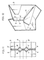
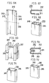
- Both the brims 2 and 2′ of a sheet state or film state container raw material 1 as shown in Fig. 1 shall be folded to both the same sides and butted mutually to each other as shown in Fig. 2 into the formation of a flat cylindrical body 3.
- Fig. 7 shows the situation where the area of fold 6 on internal bottom has been erected vertically and sided along the lateral wall, while Fig. 10 shows an entire shape of bag.
- Fig. 11 shows the state that the areas (pleats) which been folded into an inverted V-letter shape are to be removed as much as possible for getting a better outward appearance because the said areas remain on both the sides of internal bottom and impairing the outward appearance as clearly known from Figs. 8 and 9.
- the cuts 6, 6′, 7 and 7′ of approximately 90 o shall be provided to the butted section of both the brims 2 and 2′ at the symmetrical position on both the sides of inverted V-letter shaped fold in the cylindrical body 3, and shall be set in such that the center lines P and P′ of these cuts 6, 6′, 7 and 7′ may come to the lower brims (L and L′ in Fig.
- these areas are coated with the bonding agents 4 and 4′, but it is also acceptable to paste a low fusion point film like a polyethylene to these areas, press-fit it with a heat bar for depositing the said polyethylene and to paste up these areas together of a container raw material 1.
- the bonding agent or the film for heat seal like polyethylene may either be coated or pasted after folding both the brims 2 and 2′ as shown in Fig. 4 or may be coated or pasted before folding these brims.
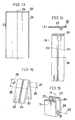
- Fig. 13 through Fig. 36 are drawings showing other embodiments.
- Fig. 13 is the drawing showing a laminate material 20 as a square shaped container raw material to be used for manufacturing a square bottom bag, and this square shaped laminate material 20 is the substance where the inside material 21 has been joined integrally with the outside material 22 as shown by the expanded sectional view in Fig. 14.
- the inside material 21 becomes the inter nal side of square bottom bag while the outside material 22 becomes the external side of square bottom bag, where the outside material 22 is made of a substance with a lower fusion point than that of inside material 21.
- Such materials as paper, bi-axially stretched polypropylene, stretched poyester, stretched polyamide, celophane, aluminium foil, stretched polystylene, polycarbonate and the like can be used for the inside material 21, while such materials as low density polyethylene, medium density polyethylene, high density polyethylene, directly chained type polyethylene, polyvinyl acetate, polypropylene, polyester, polyamide and the like can be used as the outside material 22 having a low fusion point, but in short, any combination of these materials is acceptable provided that there exists a difference in fusion points and that the outside material 22 has a lower fusion point than that of the inside material 21.
- the left side brim 23 and the right side brim 24 of this type of square shaped laminate material 20 shall be folded in line with the center line 26 in vertical direction of laminate material 20 so that its inside material 20 may come to the internal side into the situation as shown in Fig. 14B.
- the laminate material 20 which has been folded as shown in Fig. 14B shall then be folded into the state as shown in Fig. 15 along the center line 26 horizontally toward the direction that its left side brim 23 and right side brim 24 may be exposed to the external side, and moreover, in the equal distances 27 and 27 on upward and downward sides (in view of the situation shown in Fig.
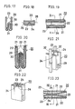
- the laminate material 20 shall be folded along two fold lines 28 and 28 in parallel with the center line 26 horizontally toward the direction that the left side brim 23 and the right side brim 24 may be folded to the internal side, then the areas of center line 26 in horizontal direction is overlapped in double into angle sections 29 and 30 as shown in Fig. 16 through Fig. 18, where the inside materials 21 face to each other inside the folded laminate material 20 as shown in Fig. 19 and Fig. 20 and the outside material 22 with a lower fusion point becomes the state positioned outside the respective inside materials 22, while at the location along the left side brim 23 and the right side brim 24 the outside materials 22 face to each other as shown in Fig. 19.
- both the outside materials 22 and 22 of left side brims 23 and 23 as well as both the outside materials 22 and 22 of right side brims 24 and 24 (see Fig. 19) which come in mutual contact with each other inside the center portion in vertical direction of laminate material 20 are fused into one body, and thus the both the external areas of left side brims and both the external areas of right side brims are mutually deposited as shown in Fig. 22 through Fig. 25.
- the laminate material 20 which has been deposited in this way is opened from the released upper brim 33 as shown in Fig. 26 and Fig. 27 and is pressed downward in a way that the lower side angle section 30 may become flat, the upper side angle section 29 moves toward the right and left directions, becomes a perpendicular flat face except for the deposided left side brims 23 and 23 and right side brims 24 and 24, and a square bottom bag 36 can be obtained that is provided with a square shaped flat bottom face 34 and a perpendicular flat lateral face 36 as shown in Fig. 28 and Fig. 29.
- the left side brims 23 and 23 and the right side brims 24 and 24 which are deposited mutually to each other protrude inwardly to the square bottom bag 36 along the center line in vertical direction of lateral face 35 while the lower section of left side brim 23 and the lower section of right side brim 24 together becomes a triangle shaped protrusive section 37 which protrudes inside the square bottom bag 36.
- Fig. 30 shows the case for depositing the external sides of left side brims 23 and 23 and the external sides of right side brims 24 and 24 to each other by use of pot shaped electrodes 32 and 32 for deposition whose lower end expands to a triangle shape in place of square rod shaped electrode plates 32 and 32 shown in Fig. 21, and in this event, the entire internal face of triangle shaped protrusive section 37 shown in Fig. 31 is deposited.
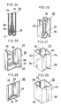
- the embodiment shown in Fig. 32 is a bag where 2 pieces each of a right angle triangle shaped notch of the same shape whose right angle top point 38 is directed to the center line 25 side in vertical direction of laminate material 20 have been provided on the left side brim 23 and the right side brim 24 respectively with a slight distance kept apart on upward and downward sides of the center line 26 in horizontal direction of laminate material 20, and if the left side brim 23 and the right side brim 24 are folded inside in line with the center line 25 in vertical direction as shown in Fig.
- two notches each on the right and left sides face to each other with the center line 25 in vertical direction as its boundary, and a regular square shaped notch in 45 o tilted direction can be formed at 2 places with a slight distance kept apart on upward and downward sides of the center line 26 in horizontal direction.
- the laminate material 20 which has been folded in this way into the state as shown in Fig. 33 shall be folded into the situation as shown in Fig. 34 along the center line 26 horizontally in the direction that the left side brim 23 and the right side brim 24 may be exposed to external side, and the laminate material 20 shall further be bent along two folded lines 28 and 28 passing through the top point 38 of a right angle toward such a direction that the left side brim 23 and the right side brim 24 may be folded inside, then the portion of center line 26 in horizontal direction becomes a angle section 29 as shown in Fig. 35, and the notches 29 having the top point 38 of right angle on the folded line 28 are mutually overlapped on both the said sides.
- both the external sides of left side brims 23 and 23, both the external sides of right side brims 24 and 24 and both the outer circumferential sides of notches 39 and 39 are deposited to each other.
- the laminate material 20 which has been deposited like the way as mentioned above is opened in the same manner as the case explained by reference to Fig. 26 through Fig. 28, such a square bottom bag can be obtained that has no triangle shaped protrusive portion 37 as shown in Fig. 31 and that is deposited with an identical width as illustrated in Fig. 36.
- Fig. 47 through Fig. 65 are views showing further additional embodiments.
- Fig. 47 is a view showing a laminate material 220 as s square shaped container raw material to be used for manufacturing a square bottom bag, and this square shaped lami nate material 220 is the substance where its inside material 221 has been joined integrally to its outside material 222 as shown in the expanded sectional view of Fig. 48.
- the inside material 221 becomes the internal side of a square bottom bag while the outside material 222 comes to the external side of a square bottom bag, where the outside material 222 uses the substance having a lower fusion point as compared with that of the inside material 221.
- Such substances as paper, biaxially stretched polypropylene, stretched polyester, stretched polyamide, celophane, aluminium foil, stretched polystylene, polycarbonate, etc. can be used for the inside material 221, while such substances as low density polyethylene, medium density polyethylene, high density polyethylene, directly chained polyethylene, polyvinyl acetate, polypropylene, polyester, polyamide, etc. can be used as the outside material 222 with a low fusion point, but in short any combination of materials is acceptable provided that there is a difference in fusion points and that the outside material 222 has a lower fusion point than that of the inside material 221.
- this laminate material 220 shall be given the fold lines in such that it may become a square shaped cylindrical body.
- Both the outside faces of lower brim section 228 which has been bent inwardly, of the laminate material 220 as shown in Fig. 51 shall be caught by such electrode plates 235 and 235 for deposition as a square rod shaped heat seal bar, a supersonic wave oscillating bar, etc. as shown in Fig. 55.
- a releasing agent shall previously be coated onto the faces of electrode plates 235 and 235 for deposition, which get in contact with the laminate material 220.
- both the outside materials at the lower brim section 228 which has been folded as a bent section 230 are fused into one body, and the lower brim section 228 can be entirely deposited as shown in Fig. 56 through Fig. 58.
- the laminate material 220 which has been deposited in this way is opened from the side of released upper brim section 227 is kept opened as shown in Fig. 59 by pressing downward the lower side bent section 230, the bent section 230 becomes a flat face with the deposited lower brim section 228 remaining protrusive to the interior, and a square bottom bag having a square shaped flat bottom face as shown in Fig. 60 and Fig. 61 can be obtained, and can be used as a bag whose upper section is opened as it is.
- the deposited upper brim section 227 and lower brim seciton 228 become the situation which has protruded to the inside of a square bottom bag 239 as shown in Fig. 65.
- Fig. 66 is a view showing a laminate material 310 as the square shaped container raw material to be used for manufacturing a bag, and this square shaped laminate material 310 is the substance where its inside material 211 has been joined integrally with its ouside material 312 as shown in the expanded sectional view of Fig. 67.
- the inside material 311 becomes the internal side of a bag while the outside material 312 comes to the external side of a bag, where the outside material 312 uses the substance with a lower fusion point than that of the inside material 311.
- Such substances as paper, biaxially stretched polypropy lene, stretched polyester, stretched polyamide, celophane, aluminium foil, stretched polystylene, polycarbonate, etc.
- the inside material 311 can be used for the inside material 311 while such substances as low density polyethylene, medium density polyethylene, high density polyethylene, directly chained polyethylene, polyvinyl acetate, polypropylene, polyester, polyamide, etc. can be used as the outside material 312 haiving a lower fusion point, but in short, any combination of materials is acceptable provided that there is a difference in fusion points and that the outside material 312 has a lowr fusion point than the inside material 311.
- the left side brim 313 and the right side brim 314 of this type of square shaped laminate material 310 shall be folded into the formation of the bent sections 315 and 315 in vertical direction in such that the inside material 311 may come to the internal side.
- both the outside materials 312 of bent section 315 are deposited to each other into one body as shown in Fig. 70 with the right and left bent sections 315 and 315 being deposited throughout their lengths respectively, thus a bag as shown in Fig. 71 can be formed.
- bent section 315 has protruded inside the bag 318 in the case of the bag 318 shown in Fig. 71, if a sealant 319 is coated onto one face of bent section 315 as shown in Fig. 72 for bonding the bent section 315 to the internal side of bag 318, a bag whose bent section won't protrude to the interior can be formed.
- This invention can be expected to provide the effects as follows by manufacturing a square bottom container according to the method as described above.
Landscapes
- Making Paper Articles (AREA)
- Bag Frames (AREA)
- Details Of Rigid Or Semi-Rigid Containers (AREA)
- Containers Having Bodies Formed In One Piece (AREA)
- Cartons (AREA)
Abstract
Description
- The present invention relates to a bag named a gazette bag whose bottom is square with the folds being provided on both the sides, and a container called a carton container for containing milks or juices.
-
- Fig. 37 through Fig. 46 show a manufacturing method of a conventional square bottom bag.
- As shown in Fig. 37, after overlapping the
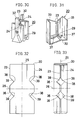
right side brim 102 and theleft side brim 103 of a square shapedbag material 101 made of paper, plastic film and the like for pasting them up together and then pasting up the internal face oflower brim section 104, fold it upward along the foldedline 105 in horizontal direction to bond it 107 to thesurface 106 ofbag material 101 as shown in Fig. 38, and fold further upward this folded and bonded section as shown in Fig. 39 to bond it 107 to thesurface 106 ofbag material 101 to form the bottom face bondedsection 108. Next, open theupper brim 109 side ofbag material 101 into a square form, make the bottom bondedsection 108 horizontal as shown in Fig. 40 while forming thelateral face 110, and not simply make the lateral face 140 to become a perpendicular plane face upto its top portion while folding upward both the sides of the bottom bonded section but also form a squareshaped bottom face 111, fold the lower section oflateral face 110 into thebottom face 111 side from thefolded line 112 to bond thebottom face 111, and then a square bottom bag having a square shapedbottom face 111 whoseupper brim 109 is opened to a square shape can be obtained as shown in Fig. 41. - Moreover, another manufacturing method of a conventional square bottom bag is to be described. After overlapping the
left side brim 102 and theright side brim 103 of a square shapedbag material 102 to paste them up together as illustrated in Fig. 37, fold the bag in such that whole the bag may become a square shaped cylindrical form, fold the lower section ofsurface 106 into a trapezoid while folding the lower section oflateral side 110 horizontally toward the inside as shown in Fig. 42, then fold the lower trapezoidal section ofsurface 106 inwardly along the foldedline 113 to paste them up together, then a square bottom bag having a square shapedbottom face 114 and whoseupper brim 109 is opened to a square shape can be obtained as illustrated in Fig. 43. - A still another manufacturing method of a conventional square bottom bag is being explained. After overlapping the
left side brim 102 and the right side brim of a square shapedbag material 101 to paste them up together as shown in Fig. 37, fold the bag in such that whole the bag may become a square shaped cylindrical form, fold it inwardly while providing thefold 115 in vertical direction at the center of lower section oflateral face 110 as shown in Fig. 44, bring thelower brims surface 106 closer mutually to each other to bond them together and form the bottom face bondedsection 116 as illustrated in Fig. 45. At the next step, fold the bottom bondedsection 116 horizontally as shown in Fig. 46 in such that the lower portion ofsurface 106 may become horizontal, and bond the lower section ofsurface 106, then a square bottom bag having a square-shaped bottom 117 and whose upper brim is opened to a square shape as shown in Fig. 46 can be formed. - However, since the overlapped areas (sealed areas) come to the bottom face in any one of the aforementioned square bottom bags, there is a fear that the bag not only becomes unstable when it is erected but the liquid may also leak from the sealed areas.
- In addition, in the case of paper, aluminium foil, or nylon and polypropylene and the like, since a low fusion point film like polyethylene having a heat sealing property is lamimated on said material in the process of manufacturing the square bottom bags, the content may get in direct contact with these laminated films and its taste may possibly change in some cases. Also the manufacturing machines and operation may become complex because the bag is to be folded intricately as described above.
- The 1st object of this invention is to present a square bottom container where the sealed areas and overpaps may not be positioned at the bottom face.
- The 2nd object of this invention is to present the manufacturing method of a square bottom container where the film for heat seal may not be positioned on the internal face of container.
- The 3rd object of this invention is to present the manufacturing method of a square bottom container which can be manufactured efficiently by use of a simple machine.
-
- Fig. 1 is a development elevation of a sheet shaped container raw material,
- Fig. 2 is a plane view of a container raw material in the state which is bent to a circle and both the brims of which have been butted together,
- Fig. 3 is a plane view of said raw material in the state where a bonding agent is coated to the outside along both the brims,
- Fig. 4 is a squint view of said raw material in the state where an inverted V-letter shaped folding is given to the area corresponding to its bottom so that the cylindrical body is formed into a W-letter shape,
- Fig. 5 is an expanded sectional view at the center of bottom section,
- Fig. 6 is a sectional view of the bottom section in the state where the areas coated with bonding agent have been pasted up together,
- Fig. 7 is a plane view of the bag in the state which has been opened after its bag making,
- Fig. 8 is a partially cut-away squint view in the process where the internal bottom is to be formed into a square shape,
- Fig. 9 is a partially cut-away squint view showing the internal bottom of a bag which has been opened completely down to its square bottom,
- Fig. 10 is a squint view showing the entire shape of a bag which has been made in accordance with the present invention,
- Fig. 11 is a plane view of a cylindrical body in the case of lessening the section protruding into the internal bottom to the minimum level by providing notches, and
- Fig. 12 is a partially cut-away squint view showing the internal bottom when a bag has been made using a cylindrical body shown in Fig. 11.
- Fig. 13 is a squint view of a laminate material,
- Fig. 14A is a partial expanded sectional view of a liminate material,
- Fig. 14B is a front view of said material in the state where both the brims have been folded,
- Fig. 14B through Fig. 16 are squint views showing the sequence for folding the laminate material,
- Fig. 17 is a sectional view taken along Line VI-VI of Fig. 16,
- Fig. 18 is a plane view of Fig. 16,
- Fig. 19 is a partial expanded horizontal sectional view of Fig. 18,
- Fig. 20 is a sectional view taken along Line IX-IX of Fig. 19,
- Fig. 21 is s squint view in the state where the liminate material has been caught between the electrode plates for deposition,
- Fig. 22 is a squint view of laminate material whose side brims have been deposited,
- Fig. 23 is a partial expanded horizontal sectional view of Fig. 22,
- Fig. 24 is a sectional view taken along Line VIII-VIII of Fig. 23,
- Fig. 21 through Fig. 28 are squint views showing the state where the laminate material whose wide brims have been deposited is to be opened,
- Fig. 29 is a squint view of a square bottom bag which has been manufactured in accordance with the method of this invention,
- Fig. 30 is a squint view of the laminate material in the state where said laminate has been caught between the electrode plates for deposition in a different way from that of Fig. 21,
- Fig. 31 is a squint sectional view of laminate material in its opened state whose side brims are deposited by the electrodes for deposition in Fig. 30,
- Fig. 32 is a front view of another invention of laminate material,
- Fig. 33 through Fig. 36 are squint views showing the sequence of manufacturing a square bottom bag using a laminate material,
- Fig. 37 through Fig. 46 are squint views showing the manufacturing method of a square bottom bag in the past.
- Fig. 47 through Fig. 65 show other embodiments, where
- Fig. 47 is a squint view of laminate material,
- Fig. 48 is a partial expanded sectional view of laminate material,
- Fig. 49 is a squint view of laminate material both the side brims of which have been pasted up together into a cylindrical state,
- Fig. 50 and Fig. 51 are squint views showing the sequence for folding the laminate material,
- Fig. 52 is a sectional view taken along Line VI-VI of Fig. 51,
- Fig. 53 is an expanded sectional view taken along VII-VII of Fig. 51, Fig. 54 is an expanded sectional view taken along Line VIII-VIII of Fig. 51,
- Fig. 55 is a squint view showing the state of liminate material whose lower brim section is to be deposited,
- Fig. 56 is an expanded sectional view taken along Line X-X of Fig. 55,
- Fig. 57 is an expanded sectional view taken along Line XI-XI of Fig. 55,
- Fig. 58 is a squint sectional view taken along Line X-II-XII of Fig. 57,
- Fig. 59 is a squint view of laminate material showing the state where said material is to be opened,
- Fig. 60 and Fig. 61 are squint views of a square bottom bag which has been manufactured by the method of this invention,
- Fig. 62 is a squint view of laminate material showing the state where its upper brim section has been deposited,
- Fig. 64 is a vertical sectional view of alminate material whose upper brim section has been deposited,
- Fig. 63 is a squint view of another square bottom bag which has been manufactured by the method of this invention, and
- Fig. 65 is a vertical sectional view of Fig. 63.
- Fig. 66 through Fig. 72 show other embodiments, where
- Fig. 66 is a squint view of laminate material both the brims of which have been folded,
- Fig. 67 is a partial expanded sectional view of laminate material,
- Fig. 68 is a squint view of laminate material which has been folded along the center line in horizontal direction,
- Fig. 69 is a squint view showing the state of depositing the bent section,
- Fig. 70 is an expanded sectional view of deposited bent section,
- Fig. 71 and Fig. 72 are squint views of a bag which has been manufactured in accordance with the method of this invention.
- First of all, the square bottom bags shown in Fig. 1 through Fig. 12 are being explained.
- Both the
brims raw material 1 as shown in Fig. 1 shall be folded to both the same sides and butted mutually to each other as shown in Fig. 2 into the formation of a flatcylindrical body 3. - Next, apply the
bonding agents butted brims - Then provide an inverted V-letter shaped fold from back of both the
brims cylindrical body 3 as shown in Fig. 5 and form the lower section ofcylindrical body 3 into a W-letter shape. - Next, press-fit the bonding agent coated faces 4 and 4′ to each other of cylindrical body for their adhesion as shown in Fig. 6.
- The bag which has been fabricated as above shall be unfolded in the arrow direction as shown in Fig. 7. When the bag is unfolded in this way, the area of inverted V-letter shaped
fold 5 is raised upward in arrow mark direction in the internal bottom of bag as shown in Fig. 8, and the bottom is opened to a square shape. Fig. 9 shows the situation where the area offold 6 on internal bottom has been erected vertically and sided along the lateral wall, while Fig. 10 shows an entire shape of bag. - Fig. 11 shows the state that the areas (pleats) which been folded into an inverted V-letter shape are to be removed as much as possible for getting a better outward appearance because the said areas remain on both the sides of internal bottom and impairing the outward appearance as clearly known from Figs. 8 and 9. First, the
cuts brims cylindrical body 3, and shall be set in such that the center lines P and P′ of thesecuts - In the aforementioned embodiment, these areas are coated with the
bonding agents raw material 1. - Next, the bonding agent or the film for heat seal like polyethylene may either be coated or pasted after folding both the
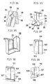
brims - Fig. 13 through Fig. 36 are drawings showing other embodiments. Fig. 13 is the drawing showing a
laminate material 20 as a square shaped container raw material to be used for manufacturing a square bottom bag, and this square shapedlaminate material 20 is the substance where theinside material 21 has been joined integrally with theoutside material 22 as shown by the expanded sectional view in Fig. 14. Theinside material 21 becomes the inter nal side of square bottom bag while theoutside material 22 becomes the external side of square bottom bag, where theoutside material 22 is made of a substance with a lower fusion point than that ofinside material 21. Such materials as paper, bi-axially stretched polypropylene, stretched poyester, stretched polyamide, celophane, aluminium foil, stretched polystylene, polycarbonate and the like can be used for theinside material 21, while such materials as low density polyethylene, medium density polyethylene, high density polyethylene, directly chained type polyethylene, polyvinyl acetate, polypropylene, polyester, polyamide and the like can be used as theoutside material 22 having a low fusion point, but in short, any combination of these materials is acceptable provided that there exists a difference in fusion points and that theoutside material 22 has a lower fusion point than that of theinside material 21. - The
left side brim 23 and theright side brim 24 of this type of square shapedlaminate material 20 shall be folded in line with thecenter line 26 in vertical direction oflaminate material 20 so that itsinside material 20 may come to the internal side into the situation as shown in Fig. 14B. Thelaminate material 20 which has been folded as shown in Fig. 14B shall then be folded into the state as shown in Fig. 15 along thecenter line 26 horizontally toward the direction that itsleft side brim 23 andright side brim 24 may be exposed to the external side, and moreover, in theequal distances center line 26 in horizontal direction, thelaminate material 20 shall be folded along twofold lines center line 26 horizontally toward the direction that theleft side brim 23 and theright side brim 24 may be folded to the internal side, then the areas ofcenter line 26 in horizontal direction is overlapped in double intoangle sections inside materials 21 face to each other inside the foldedlaminate material 20 as shown in Fig. 19 and Fig. 20 and theoutside material 22 with a lower fusion point becomes the state positioned outside the respectiveinside materials 22, while at the location along theleft side brim 23 and theright side brim 24 theoutside materials 22 face to each other as shown in Fig. 19. - After applying a releasing agent to the
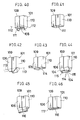
lower face 31 ofangle section 30 at the lower side oflaminate material 20 which has been bent in this way, the center section in vertical direction oflaminate material 20 shall be caught betweensuch electrode plates electrode plates laminate material 20. When the center portion in vertical direction oflaminate material 20 is heated up in the temperature range lower than the fusion point ofinside material 21 but higher than the fusion point ofoutside material 22 by use of theelectrode plates outside materials outside materials laminate material 20 are fused into one body, and thus the both the external areas of left side brims and both the external areas of right side brims are mutually deposited as shown in Fig. 22 through Fig. 25. - When the
laminate material 20 which has been deposited in this way is opened from the releasedupper brim 33 as shown in Fig. 26 and Fig. 27 and is pressed downward in a way that the lowerside angle section 30 may become flat, the upperside angle section 29 moves toward the right and left directions, becomes a perpendicular flat face except for the deposided left side brims 23 and 23 and right side brims 24 and 24, and a squarebottom bag 36 can be obtained that is provided with a square shaped flatbottom face 34 and a perpendicular flatlateral face 36 as shown in Fig. 28 and Fig. 29. The left side brims 23 and 23 and the right side brims 24 and 24 which are deposited mutually to each other protrude inwardly to the squarebottom bag 36 along the center line in vertical direction oflateral face 35 while the lower section ofleft side brim 23 and the lower section ofright side brim 24 together becomes a triangle shapedprotrusive section 37 which protrudes inside the squarebottom bag 36. - Fig. 30 shows the case for depositing the external sides of left side brims 23 and 23 and the external sides of right side brims 24 and 24 to each other by use of pot shaped
electrodes electrode plates protrusive section 37 shown in Fig. 31 is deposited. - The embodiment shown in Fig. 32 is a bag where 2 pieces each of a right angle triangle shaped notch of the same shape whose right
angle top point 38 is directed to thecenter line 25 side in vertical direction oflaminate material 20 have been provided on theleft side brim 23 and theright side brim 24 respectively with a slight distance kept apart on upward and downward sides of thecenter line 26 in horizontal direction oflaminate material 20, and if theleft side brim 23 and theright side brim 24 are folded inside in line with thecenter line 25 in vertical direction as shown in Fig. 33, two notches each on the right and left sides face to each other with thecenter line 25 in vertical direction as its boundary, and a regular square shaped notch in 45o tilted direction can be formed at 2 places with a slight distance kept apart on upward and downward sides of thecenter line 26 in horizontal direction. - The
laminate material 20 which has been folded in this way into the state as shown in Fig. 33 shall be folded into the situation as shown in Fig. 34 along thecenter line 26 horizontally in the direction that theleft side brim 23 and theright side brim 24 may be exposed to external side, and thelaminate material 20 shall further be bent along two foldedlines top point 38 of a right angle toward such a direction that theleft side brim 23 and theright side brim 24 may be folded inside, then the portion ofcenter line 26 in horizontal direction becomes aangle section 29 as shown in Fig. 35, and thenotches 29 having thetop point 38 of right angle on the foldedline 28 are mutually overlapped on both the said sides. - If the laminate material which has been folded in this way is caught from both the sides of the center line in vertical direction with pot shaped
electrodes notches laminate material 20 which has been deposited like the way as mentioned above is opened in the same manner as the case explained by reference to Fig. 26 through Fig. 28, such a square bottom bag can be obtained that has no triangle shapedprotrusive portion 37 as shown in Fig. 31 and that is deposited with an identical width as illustrated in Fig. 36. - Fig. 47 through Fig. 65 are views showing further additional embodiments.
- Fig. 47 is a view showing a
laminate material 220 as s square shaped container raw material to be used for manufacturing a square bottom bag, and this square shapedlami nate material 220 is the substance where itsinside material 221 has been joined integrally to itsoutside material 222 as shown in the expanded sectional view of Fig. 48. Theinside material 221 becomes the internal side of a square bottom bag while theoutside material 222 comes to the external side of a square bottom bag, where theoutside material 222 uses the substance having a lower fusion point as compared with that of theinside material 221. Such substances as paper, biaxially stretched polypropylene, stretched polyester, stretched polyamide, celophane, aluminium foil, stretched polystylene, polycarbonate, etc. can be used for theinside material 221, while such substances as low density polyethylene, medium density polyethylene, high density polyethylene, directly chained polyethylene, polyvinyl acetate, polypropylene, polyester, polyamide, etc. can be used as theoutside material 222 with a low fusion point, but in short any combination of materials is acceptable provided that there is a difference in fusion points and that theoutside material 222 has a lower fusion point than that of theinside material 221. - After the
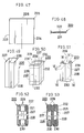
left side brim 223 and theright side brim 224 of this type of a square shapedlaminate material 220 have been folded to the side ofvertical center line 225 so that theinside material 221 may be folded inside, and the left side brim has been pasted up with theright side brim 224 with a bonding agent into the formation of a bondedsection 226 in vertical direction as shown in Fig. 49, thislaminate material 220 shall be given the fold lines in such that it may become a square shaped cylindrical body. - Next, if the
upper brim section 227 and thelower brim section 228 oflaminate material 220 which has been formed into a square shaped cylindrical body is folded inwardly to the cylindrical body as shown in Fig. 50 to form the foldedsections respective center lines outside materials 222 face to each other entirely on the internal sides of foldedsections - Both the outside faces of
lower brim section 228 which has been bent inwardly, of thelaminate material 220 as shown in Fig. 51 shall be caught bysuch electrode plates electrode plates laminate material 220. And if the outside oflaminate material 220 into which thelower brim section 228 has been folded by theelectrode plates inside material 221 but higher than the fusion point ofoutside material 222 having a lower fusion point, both the outside materials at thelower brim section 228 which has been folded as abent section 230 are fused into one body, and thelower brim section 228 can be entirely deposited as shown in Fig. 56 through Fig. 58. - If the
laminate material 220 which has been deposited in this way is opened from the side of releasedupper brim section 227 is kept opened as shown in Fig. 59 by pressing downward the lower sidebent section 230, thebent section 230 becomes a flat face with the depositedlower brim section 228 remaining protrusive to the interior, and a square bottom bag having a square shaped flat bottom face as shown in Fig. 60 and Fig. 61 can be obtained, and can be used as a bag whose upper section is opened as it is. - If both the outside faces at the upper brim section 227 (see Fig. 61) which has been bent inwardly as shown in Fig. 62, containing a filler material inside the aforementioned square
bottom bag 237, are caught between theelectrode plates upper brim section 227 which has been folded as abent section 229 are deposited into one body and the upper brim section is entirely deposited as shown in Fig. 64, thereby a squarebottom bag 239 whose upper face has also been sealed as shown in Fig. 63 can be obtained. - The deposited
upper brim section 227 andlower brim seciton 228 become the situation which has protruded to the inside of a squarebottom bag 239 as shown in Fig. 65. - Moreover, additional embodiments are introduced in Fig. 66 through Fig. 72.
- Fig. 66 is a view showing a
laminate material 310 as the square shaped container raw material to be used for manufacturing a bag, and this square shapedlaminate material 310 is the substance where its inside material 211 has been joined integrally with itsouside material 312 as shown in the expanded sectional view of Fig. 67. Theinside material 311 becomes the internal side of a bag while theoutside material 312 comes to the external side of a bag, where theoutside material 312 uses the substance with a lower fusion point than that of theinside material 311. Such substances as paper, biaxially stretched polypropy lene, stretched polyester, stretched polyamide, celophane, aluminium foil, stretched polystylene, polycarbonate, etc. can be used for theinside material 311 while such substances as low density polyethylene, medium density polyethylene, high density polyethylene, directly chained polyethylene, polyvinyl acetate, polypropylene, polyester, polyamide, etc. can be used as theoutside material 312 haiving a lower fusion point, but in short, any combination of materials is acceptable provided that there is a difference in fusion points and that theoutside material 312 has a lowr fusion point than theinside material 311. - The
left side brim 313 and theright side brim 314 of this type of square shapedlaminate material 310 shall be folded into the formation of thebent sections inside material 311 may come to the internal side. - Next, if the
laminate material 310 is folded along itscenter line 316 in horizontal direction into the state as shown in Fig. 68 so that thesebent sections outside materials 312 face to each other in thebent sections bent sections laminate material 310 which has been folded as shown in Fig. 68 shall be caught betweensuch electrode plates electrode plate 317 for deposition, which gets in contact with thelaminate material 310. And when the outside oflaminate material 310 into which thebent section 315 has been folded is heated up within the temperature range lower than the fusion point ofinside material 311 but higher than the fusion point of outside material having a lower fusion point by use of theelectrode plates outside materials 312 ofbent section 315 are deposited to each other into one body as shown in Fig. 70 with the right and leftbent sections - Though the
bent section 315 has protruded inside thebag 318 in the case of thebag 318 shown in Fig. 71, if asealant 319 is coated onto one face ofbent section 315 as shown in Fig. 72 for bonding thebent section 315 to the internal side ofbag 318, a bag whose bent section won't protrude to the interior can be formed. - This invention can be expected to provide the effects as follows by manufacturing a square bottom container according to the method as described above.
- a. Because of the absence of sealed areas and overlapped areas on the square bottom face, the bag becomes stable when it has been erected, and moreover there is no fear of leakage and pin holes.
- b. Since the laminate film for heat sealing is not positioned in the internal face of container, its contents are protected against getting in direct contact with this laminate film with no subsequent change in taste and change in quality.
- c. A manufacturing machine becomes simple in construction because the square bottom can be formed only by folding the sheet. In addition, the bags can be produced continuously on the production line and therefore the production cost can be reduced.
Claims (8)
- (1) The manufacturing method of a square bottom container comprising the process for forming a flat cylindrical body by folding both the brims of a sheet state container raw material to an identical face side and butting them together,
a process for coating a bonding agent to the outside of both the butted brims,
a process process for providing an inverted V-letter shaped form to the lower section of cylindrical body from back of both the brims of said cylindrical body into the formation of a W-letter shape of said section, and
a process for press-fitting from outside the section of cylindrical body formed into W-letter shape for its adhesion, which has been coated with said bonding agent. - (2) A manufacturing method of a square bottom container as described in Claim 1, wherein heat seal layers are formed on the outsides of both the butted brims for pressing and depositing these heat seal layers to each other, in place of a bonding agent.
- (3) A manufacturing method of a square bottom container as described in Claim 1, wherein bonding agent or heat seal layers have previously been formed on the outsides of both the brims of a sheet shaped container raw material and they are folded and butted to each other into the formation of a flat cylindrical body.
- (4) A manufacturing method of a square bottom container as described in Claim (1), wherein the cuts of about 90o which are opposite to each other are formed at 2 places on both the brims of a sheet shaped container raw material for continuously forming the bonding agent or heat seal layer along the brim of these cuts from outsides of both the brims of a sheet shaped container raw material, and an inverted V-letter shaped fold against a flat cylindrical body is to be provided in the midway of this cut, moreover a W-letter shaped folded section being provided at the center of cut.
- (5) A manufacturing method of a square bottom bag with such a feature that both the sides of a square shaped laminate material where its inside material has been integrated with the outside material having a lower fusion point than that of inside material are to be folded inwardly while matching both the right and left side brims of said laminate material to the center line in vertical direction of said laminate material, then the aforesaid laminate material is to be folded along the center line horizontally toward the direction that the foresaid brims on both the sides may be exposed to outside, and moreover with an equal distance being provided on upward and downward sides from said center line in horizontal direction, the aforesaid laminate material is folded into the direction where the aforesaid brims on both the right and left sides may be folded along two bent lines in parallel with said center line in horizontal direction, for catching the center line in vertical direction of said laminate material from both the faces with between the heating elements for deposition, and for depositing both the outsides of said left side brims and both the outsides of said right side brims.
- (6) A manufacturing method of a square bottom bag as described in Claim (5) with such a feature that, when 2 pieces each of right-angled triangle shaped notch of the same shape where the top point of right angle has been directed to the center line side in vertical direction of laminate material have been provided on the left side brim and the right side brim respectively with a slight distance kept apart on upward and downward sides of the center line in horizontal direction of laminate material and when both the sides of said laminate material have been folded inside the brims on both the right and left sides of said laminate material matched to the center line in vertical direction of said laminate material, said two notches on both the right and left sides face to each other with the center line in vertical direction of laminate material as its boundary and a squint direction regular square shaped notch may be formed at two places with a slight distance kept apart on upward and downward sides of the cneter line in horizontal direction.
- (7) A manufacturing method of a square bottom bag with such a feature that, after both the right and left brims of a square laminate material where the inside material has been integrated with the outside material having a lower fusion point than said inside material have been pasted up to each other into the formation of a square shaped cylindrical body where the aforesaid inside material is positioned to the internal side, and the upper brim section and the lower brim section of said cylindrical body have been folded inwardly to said cylindrical body, both the right and left sides opposite to said cylindrical body is to be folded to the inward side of said cylindrical body with the center lines in vertical direction respectively on both the said right and left sides as their folds, and at least either both the outsides of upper brim or both the outsides of lower brim of said laminate material are deposited to each other.
- (8) A manufacturing method of a square bottom bag with such a feature that, after both the right and left side brims of a square shaped laminate material where its inside material has been integrated with its outside material having a lower fusion point than said inside material have been folded inside for the formtion of bent sections in vertical direction on both the right and left sides of said laminate material, said laminate material is to be folded along the center line in horizontal direction toward the direction that said bent sections may come to the inside for depositing both the outsides of said bent sections to each other.
Priority Applications (1)
| Application Number | Priority Date | Filing Date | Title |
|---|---|---|---|
| EP93203731A EP0605931A1 (en) | 1988-05-17 | 1989-05-16 | Method for the manufacture of square bottom containers |
Applications Claiming Priority (4)
| Application Number | Priority Date | Filing Date | Title |
|---|---|---|---|
| JP118274/88 | 1988-05-17 | ||
| JP118273/88 | 1988-05-17 | ||
| JP63118274A JPH069892B2 (en) | 1988-05-17 | 1988-05-17 | Square bottom bag manufacturing method |
| JP63118273A JPH01288427A (en) | 1988-05-17 | 1988-05-17 | Manufacture of angular bottom bag |
Related Child Applications (4)
| Application Number | Title | Priority Date | Filing Date |
|---|---|---|---|
| EP93203732 Division | 1989-05-16 | ||
| EP93203731.0 Division-Into | 1993-12-30 | ||
| EP93203733.6 Division-Into | 1993-12-30 | ||
| EP93203732.8 Division-Into | 1993-12-30 |
Publications (3)
| Publication Number | Publication Date |
|---|---|
| EP0342935A2 true EP0342935A2 (en) | 1989-11-23 |
| EP0342935A3 EP0342935A3 (en) | 1991-07-03 |
| EP0342935B1 EP0342935B1 (en) | 1994-08-31 |
Family
ID=26456236
Family Applications (2)
| Application Number | Title | Priority Date | Filing Date |
|---|---|---|---|
| EP89304951A Expired - Lifetime EP0342935B1 (en) | 1988-05-17 | 1989-05-16 | Manufacturing method of square bottom containers |
| EP93203731A Withdrawn EP0605931A1 (en) | 1988-05-17 | 1989-05-16 | Method for the manufacture of square bottom containers |
Family Applications After (1)
| Application Number | Title | Priority Date | Filing Date |
|---|---|---|---|
| EP93203731A Withdrawn EP0605931A1 (en) | 1988-05-17 | 1989-05-16 | Method for the manufacture of square bottom containers |
Country Status (4)
| Country | Link |
|---|---|
| US (1) | US5006186A (en) |
| EP (2) | EP0342935B1 (en) |
| AT (1) | ATE110627T1 (en) |
| DE (1) | DE68917782T2 (en) |
Families Citing this family (8)
| Publication number | Priority date | Publication date | Assignee | Title |
|---|---|---|---|---|
| US5165799A (en) * | 1978-10-10 | 1992-11-24 | Wood James R | Flexible side gusset square bottom bags |
| US5830118A (en) * | 1995-09-15 | 1998-11-03 | Klockner Bartelt, Inc. | Packaging machine for forming free-standing pouches |
| ATE222178T1 (en) * | 1995-12-21 | 2002-08-15 | Windmoeller & Hoelscher | METHOD AND DEVICE FOR PRODUCING SACKS FROM SINGLE OR MULTI-LAYER TUBE SECTIONS |
| WO2003024821A1 (en) * | 2001-09-19 | 2003-03-27 | Polymer Packaging, Inc. | Flat bottom, stand up bag and method of manufacturing the same |
| US20110019942A1 (en) * | 2009-07-22 | 2011-01-27 | Carmelo Piraneo | Flat Bottom, Stand-Up Bag and Method of Manufacturing Same |
| US10322851B2 (en) * | 2016-12-14 | 2019-06-18 | Ah Moi TAN | Self-supporting plastic bag and method for manufacturing same |
| WO2022238301A1 (en) * | 2021-05-12 | 2022-11-17 | Holweg Group | Flexible bag having a convertible bottom, method and machine for manufacturing same |
| FR3122847B1 (en) * | 2021-05-12 | 2023-05-12 | Holweg Group | Process and machine for manufacturing a flexible bag of the envelope type, in particular with reinforcement |
Family Cites Families (13)
| Publication number | Priority date | Publication date | Assignee | Title |
|---|---|---|---|---|
| US287753A (en) * | 1883-10-30 | Geobge o | ||
| US775268A (en) * | 1904-01-12 | 1904-11-15 | Willis P Flowers | Bag. |
| US2162258A (en) * | 1936-11-17 | 1939-06-13 | Pneumatic Scale Corp | Paper bag |
| US2157794A (en) * | 1937-12-18 | 1939-05-09 | Evans Case Co | Making receptacles |
| US2282258A (en) * | 1940-06-07 | 1942-05-05 | Wingfoot Corp | Plasticized and nonplasticized double wall bag |
| GB951437A (en) * | 1959-09-09 | 1964-03-04 | Dale Products Plastics Ltd | Improvements in and relating to plastic bags and the manufacture thereof |
| US3133478A (en) * | 1960-11-05 | 1964-05-19 | Honsel Karl Heinz | Method of and machine for manufacture of block bottom bags |
| FR1283386A (en) * | 1961-01-16 | 1962-02-02 | Billeruds Ab | Material used for making bags, process for obtaining these bags and bags thus obtained |
| US3357322A (en) * | 1965-01-12 | 1967-12-12 | Lester D Gill | Coated box and method of making |
| US3358903A (en) * | 1966-03-31 | 1967-12-19 | West Virginia Pulp & Paper Co | Paper bags having leak-proof seams |
| US3860164A (en) * | 1967-12-28 | 1975-01-14 | Howard S Dworkin | End construction for bellows type envelopes and the like |
| US3955749A (en) * | 1974-06-28 | 1976-05-11 | Eugene Turkenkopf | Expansible envelope |
| US4566927A (en) * | 1978-10-10 | 1986-01-28 | Wood James R | Pattern bonding of webs by electron beam curing |
-
1989
- 1989-05-16 AT AT89304951T patent/ATE110627T1/en not_active IP Right Cessation
- 1989-05-16 EP EP89304951A patent/EP0342935B1/en not_active Expired - Lifetime
- 1989-05-16 DE DE68917782T patent/DE68917782T2/en not_active Expired - Fee Related
- 1989-05-16 EP EP93203731A patent/EP0605931A1/en not_active Withdrawn
- 1989-05-17 US US07/353,096 patent/US5006186A/en not_active Expired - Fee Related
Also Published As
| Publication number | Publication date |
|---|---|
| US5006186A (en) | 1991-04-09 |
| EP0605931A1 (en) | 1994-07-13 |
| EP0342935A3 (en) | 1991-07-03 |
| DE68917782D1 (en) | 1994-10-06 |
| DE68917782T2 (en) | 1995-01-05 |
| ATE110627T1 (en) | 1994-09-15 |
| EP0342935B1 (en) | 1994-08-31 |
Similar Documents
| Publication | Publication Date | Title |
|---|---|---|
| US4854733A (en) | Portable packing bag having a two section loop handle | |
| US4989736A (en) | Packing container and blank for use in the manufacture thereof | |
| EP0763472B1 (en) | Plastic coated paper container with cut edges protected against moisture | |
| EP0197614A2 (en) | Bottom design of packing containers | |
| US20210339914A1 (en) | Square-bottomed packaging bag, packaging body, and method of manufacturing square-bottomed packaging bag | |
| EP0342935A2 (en) | Manufacturing method of square bottom containers | |
| US5236531A (en) | Manufacturing method of square bottom containers | |
| US12103737B2 (en) | Rectangular-bottomed packaging bag, and method for manufacturing rectangular-bottomed packaging bag | |
| JP2018167568A (en) | Method of producing gusset bag | |
| RU2216450C2 (en) | Method of production of semifinished products for bags with sealed edges | |
| CS229912B2 (en) | Citern cut sizes from flexible sheet material | |
| JP2001225849A (en) | Bag body and filling method | |
| JPH046049A (en) | Packing bag | |
| JP4341178B2 (en) | 3D shape memory pouch | |
| EP0277517A1 (en) | A blank having folding lines for forming a container | |
| JPH0911365A (en) | Method for manufacturing large gusset square bottom bag | |
| JP2022183062A (en) | Gazette bag body with zipper and gazette bag package with zipper | |
| JP7752550B2 (en) | Gusset bag with zipper and gusset bag package | |
| JPS5815305Y2 (en) | square bottom bag | |
| KR200194284Y1 (en) | Refill pouch | |
| JPH0624787B2 (en) | Square bottom container manufacturing method | |
| JPH0528185Y2 (en) | ||
| JPH08217055A (en) | Liquid packaging container | |
| JP7028571B2 (en) | Gazette bag | |
| JPH09132246A (en) | Multilayer bag and its body sealing method |
Legal Events
| Date | Code | Title | Description |
|---|---|---|---|
| PUAI | Public reference made under article 153(3) epc to a published international application that has entered the european phase |
Free format text: ORIGINAL CODE: 0009012 |
|
| AK | Designated contracting states |
Kind code of ref document: A2 Designated state(s): AT BE CH DE ES FR GB GR IT LI LU NL SE |
|
| PUAL | Search report despatched |
Free format text: ORIGINAL CODE: 0009013 |
|
| AK | Designated contracting states |
Kind code of ref document: A3 Designated state(s): AT BE CH DE ES FR GB GR IT LI LU NL SE |
|
| 17P | Request for examination filed |
Effective date: 19911223 |
|
| 17Q | First examination report despatched |
Effective date: 19920917 |
|
| GRAA | (expected) grant |
Free format text: ORIGINAL CODE: 0009210 |
|
| AK | Designated contracting states |
Kind code of ref document: B1 Designated state(s): AT BE CH DE ES FR GB GR IT LI LU NL SE |
|
| PG25 | Lapsed in a contracting state [announced via postgrant information from national office to epo] |
Ref country code: NL Effective date: 19940831 Ref country code: GR Free format text: LAPSE BECAUSE OF FAILURE TO SUBMIT A TRANSLATION OF THE DESCRIPTION OR TO PAY THE FEE WITHIN THE PRESCRIBED TIME-LIMIT Effective date: 19940831 Ref country code: ES Free format text: THE PATENT HAS BEEN ANNULLED BY A DECISION OF A NATIONAL AUTHORITY Effective date: 19940831 Ref country code: BE Effective date: 19940831 Ref country code: AT Effective date: 19940831 |
|
| REF | Corresponds to: |
Ref document number: 110627 Country of ref document: AT Date of ref document: 19940915 Kind code of ref document: T |
|
| XX | Miscellaneous (additional remarks) |
Free format text: TEILANMELDUNG 93203732.8 EINGEREICHT AM 16/05/89. |
|
| ET | Fr: translation filed | ||
| ITF | It: translation for a ep patent filed | ||
| REF | Corresponds to: |
Ref document number: 68917782 Country of ref document: DE Date of ref document: 19941006 |
|
| EAL | Se: european patent in force in sweden |
Ref document number: 89304951.0 |
|
| NLV1 | Nl: lapsed or annulled due to failure to fulfill the requirements of art. 29p and 29m of the patents act | ||
| PGFP | Annual fee paid to national office [announced via postgrant information from national office to epo] |
Ref country code: GB Payment date: 19950504 Year of fee payment: 7 |
|
| PGFP | Annual fee paid to national office [announced via postgrant information from national office to epo] |
Ref country code: SE Payment date: 19950526 Year of fee payment: 7 |
|
| PGFP | Annual fee paid to national office [announced via postgrant information from national office to epo] |
Ref country code: FR Payment date: 19950530 Year of fee payment: 7 |
|
| PG25 | Lapsed in a contracting state [announced via postgrant information from national office to epo] |
Ref country code: LU Free format text: LAPSE BECAUSE OF NON-PAYMENT OF DUE FEES Effective date: 19950531 |
|
| PLBE | No opposition filed within time limit |
Free format text: ORIGINAL CODE: 0009261 |
|
| STAA | Information on the status of an ep patent application or granted ep patent |
Free format text: STATUS: NO OPPOSITION FILED WITHIN TIME LIMIT |
|
| PGFP | Annual fee paid to national office [announced via postgrant information from national office to epo] |
Ref country code: CH Payment date: 19950724 Year of fee payment: 7 |
|
| PGFP | Annual fee paid to national office [announced via postgrant information from national office to epo] |
Ref country code: DE Payment date: 19950731 Year of fee payment: 7 |
|
| 26N | No opposition filed | ||
| PG25 | Lapsed in a contracting state [announced via postgrant information from national office to epo] |
Ref country code: GB Effective date: 19960516 |
|
| PG25 | Lapsed in a contracting state [announced via postgrant information from national office to epo] |
Ref country code: SE Effective date: 19960517 |
|
| PG25 | Lapsed in a contracting state [announced via postgrant information from national office to epo] |
Ref country code: LI Effective date: 19960531 Ref country code: CH Effective date: 19960531 |
|
| GBPC | Gb: european patent ceased through non-payment of renewal fee |
Effective date: 19960516 |
|
| REG | Reference to a national code |
Ref country code: CH Ref legal event code: PL |
|
| PG25 | Lapsed in a contracting state [announced via postgrant information from national office to epo] |
Ref country code: FR Effective date: 19970131 |
|
| PG25 | Lapsed in a contracting state [announced via postgrant information from national office to epo] |
Ref country code: DE Effective date: 19970201 |
|
| EUG | Se: european patent has lapsed |
Ref document number: 89304951.0 |
|
| REG | Reference to a national code |
Ref country code: FR Ref legal event code: ST |
|
| PG25 | Lapsed in a contracting state [announced via postgrant information from national office to epo] |
Ref country code: IT Free format text: LAPSE BECAUSE OF NON-PAYMENT OF DUE FEES;WARNING: LAPSES OF ITALIAN PATENTS WITH EFFECTIVE DATE BEFORE 2007 MAY HAVE OCCURRED AT ANY TIME BEFORE 2007. THE CORRECT EFFECTIVE DATE MAY BE DIFFERENT FROM THE ONE RECORDED. Effective date: 20050516 |