EP0342901A2 - Analysegerät für binäre Gasmischungen und Analyseverfahren - Google Patents
Analysegerät für binäre Gasmischungen und Analyseverfahren Download PDFInfo
- Publication number
- EP0342901A2 EP0342901A2 EP89304892A EP89304892A EP0342901A2 EP 0342901 A2 EP0342901 A2 EP 0342901A2 EP 89304892 A EP89304892 A EP 89304892A EP 89304892 A EP89304892 A EP 89304892A EP 0342901 A2 EP0342901 A2 EP 0342901A2
- Authority
- EP
- European Patent Office
- Prior art keywords
- gas
- cell
- cells
- analyzer instrument
- thermistor
- Prior art date
- Legal status (The legal status is an assumption and is not a legal conclusion. Google has not performed a legal analysis and makes no representation as to the accuracy of the status listed.)
- Withdrawn
Links
Images


Classifications
-
- G—PHYSICS
- G01—MEASURING; TESTING
- G01N—INVESTIGATING OR ANALYSING MATERIALS BY DETERMINING THEIR CHEMICAL OR PHYSICAL PROPERTIES
- G01N25/00—Investigating or analyzing materials by the use of thermal means
- G01N25/18—Investigating or analyzing materials by the use of thermal means by investigating thermal conductivity
Definitions
- This invention relates in general to percent compositional analysis of a binary gas mixture, and more particularly, to a binary gas analyzer instrument and analysis method effective to indicate percent contamination of a cooling gas within a turbine generator.
- the principal prior art means for monitoring air contamination within a gas cooled generator was developed by the present applicants several decades ago.
- This monitoring means consists of a Golay cell and a reference cell mounted in a brass housing together with a power unit, a flowrator, a wheatstone bridge circuit, and an indicating meter.
- Two arms of the bridge consist of a filament each and the other two consist of bridge completion resistors of comparable resistance value.
- One of the filaments is enclosed in the reference cavity of the detector in sealed air, while the other is placed in the measuring cell having the mixture to be measured.
- Imbalances in thermal conductivity between the two cells, as measured by imbalances in the resistances of the two filaments are indicated by the bridge imbalance current and serve as the measure of the composition of the mixture.
- the instrument offers a reasonable indication of the composition of the binary mixtures used, it does have several shortcomings.
- this prior art instrument is very sensitive to variations in supply voltage and to the temperature of the detector block.
- the accuracy and sensitivity are relatively poor in the critical 0% to 20% contamination region, and the instrument requires manual calibration during each use.
- the present invention comprises a gas analyzer instrument and analysis method capable of determining the percent composition of a gas mixture composed of two known constituents.
- the analyzer instrument includes a first reference cell having a first gas therein with a thermal conductivity near the thermal conductivity of one of the known constituent gases, and a measurement cell containing the binary gas mixture to be analyzed.
- a thermistor is positioned within each of the cells and maintaining means is provided for maintaining the cells at a substantially constant temperature.
- the instrument also includes electric current supply means for providing a constant current to each of the thermistors for self heating, with the gas in each of the cells conducting heat away from the thermistor therein, and voltage measuring means selectably connectable across each of the thermistors for measuring the voltage drop across the thermistors.
- computational means provides for automatic translation of the measured voltage drop across the measurement cell thermistor into a percent compositional reading of the binary gas constituents. Translation is accomplished by the computational means with reference to the voltage drop across the first reference cell thermistor.
- the analyzer instrument is capable of determining the percent composition of the constituents within each of a plurality of different binary gas mixtures.
- This embodiment includes a second reference cell which has a second gas therein with a thermal conductivity near the thermal conductivity of one of the constituent gases of the plurality of different binary gas mixtures.
- the computational means translates the voltage drop across the measurement cell thermistor into a percent compositional reading of the constitutents for a particular binary gas mixture utilizing the voltage drop across at least one of the first and second cell thermistors as a reference.
- the invention comprises an analysis method for determining the percent composition of a binary gas mixture of known constituents which includes the steps of: providing a first reference cell and a second reference cell, each cell having a thermistor therein, said cells also having a first gas and a second gas sealed therein, respectively, the first gas having a thermal conductivity near the thermal conductivity of one of the two constituent gases and the second gas having a thermal conductivity near the thermal conductivity of the other of the two constituent gases; providing a measurement cell with a thermistor therein; introducing the binary gas mixture into the measurement cell; maintaining the cells at a substantially constant temperature; supplying a substantially constant electric current to each of the thermistors for heating thereof, the gas in each of said cells conducting heat away from the thermistor therein; measuring the voltage drop across each of the thermistors; and correlating the voltage drop across the measurement cell thermistor with a percent compositional reading of the binary gas mixture constituents, said correlating step utilizing the voltage drop across at least one of the first and
- an improved analyzer instrument and analysis method capable of being used to determine the percent composition of a gas mixture composed of two known constituents
- an improved analyzer instrument and analysis method capable of being used to determine the percent composition of the constituents within each of a plurality of different known binary gas mixtures
- such an instrument and method which is capable of safely monitoring operation of a hydrogen gas cooled turbo generator
- such an instrument and method which is capable of accurately determining the percent composition of a binary gas mixture within a turbo generator
- such an instrument and method which requires no manual adjustment while monitoring operation of a hydrogen gas cooled turbo generator such an instrument and method which requires no manual adjustment while monitoring operation of a hydrogen gas cooled turbo generator.
- the novel apparatus and method of this invention utilizes two basic principals, namely: (1) different gases have different thermal conductivities, and (2) thermistors positioned within gas filled chambers and supplied with constant current stabilize at different voltages which depend upon the heat conductivity of the respective surrounding gases.
- a detailed description of one invention embodiment incorporating these principals is provided herein with reference its use in the turbo power generation field.
- the appended claims are intended to encompass all such uses.
- compositional percent information for three different, known binary gas mixtures, i.e., air and carbon dioxide (CO2), CO2 and hydrogen, and air and hydrogen. These mixtures occur at different times during the filling, operation and purging of the turbo generator. Attention to percent contamination of air in hydrogen is particularly important because of its explosive nature at certain critical levels. Constant monitoring is required since air contamination within the generator is a consistent problem resulting from the tendency of pressurized hydrogen gas to leak from the generator.
- the embodiment described herein contains only two reference cells in addition to the measurement cell.
- Such a cell configuration allows for the calculation of percent composition of each of said three mixtures within an acceptable range of error for each mixture.
- instrument accuracy can be improved by having reference gases at each end of each measurement range, i.e., by having reference gases which comprise the constituent gases of each binary mixture to be evaluated.
- the invention can be implemented with only one reference cell having a gas sealed therein which comprises a constituent gas of the binary mixture to be evaluated, or has a thermal conductivity near that of a constituent gas.
- a first reference cell has a first gas sealed therein with a thermal conductivity near either that of air or hydrogen gas
- the second reference cell has a second gas sealed therein with a thermal conductivity near the thermal conductivity of the other of said two constituent gases.
- the first reference gas comprises nitrogen, since nitrogen gas is known to closely approximate the thermal conductivity of air and is more readily available in bottled form, and the second reference gas comprises heluim, which is inert and is known to closely approximate the thermal conductivity of hydrogen, which has a much greater tendency to leak from a sealed container.
- thermistors undergo a heating effect from the flow of a constant current therethrough, heat is conducted by the constrained gases radially outwards until the temperature of each thermistor stabilizes.
- the respective stabilization temperatures are dependent upon the thermal conductivity of the gas sealed within each cell, and at equilibrium, the voltage measured across each cell thermistor provides an indication of thermal conductivity of the gas constrained therein. Provision of a constant current to the thermistors is important to eliminate error which would otherwise be introduced due to current changes causing self-heating changes within the thermistors.
- the analyzer instrument is manually set to indicate that the mixture under analysis comprises % hydrogen in air, with 99% being a typical operating percentage.
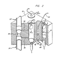
- Cell 10 comprises a cylindrical bore within a block 12, preferably manufactured of brass. As shown, cell 10 is a sealed reference cell, with one end closed by a hermetic seal 15 and the other end by a sealed fill tube 17.
- thermistor 14 Within cell 10 is a thermistor 14 radially suspended by very fine electric leads 16 and 18. Fine leads 16 and 18 are electrically connected to leads 20 and 22, respectively, and are utilized to minimize thermal conduction through the wires from thermistor 14.
- Hermetic seal 15 is a commercially available item which includes a disk-shaped, metallic rim 21 and a central, electrically isolating glass portion 23. Seal 15 is soldered airtight to block 12. Lead 20 is electrically grounded to block 12, via metallic rim 21, and lead 22 is electrically isolated from block 12 by glass seal 23.
- Cell 10 can be constructed of various shapes as desired, such as cylindrical, spherical or cubical; however, the distance “d” from thermistor 14 to wall 13 of cell 10 is important. This is because as distance “d” increases, net thermal conductivity of the gas filled chamber decreases, which means the resulting stabilization temperature rises, thereby making it more difficult to measure differences in voltage drop across the thermistors.
- cell 10 is sealed at its bottom end by a closed fill tube 17.
- Fill tube 17 consists of standard copper tubing which resides within a bore 28 at the bottom of cell 10. Filling of cell 10 with a reference gas entails evacuating the cell through tube 17 and then filling with the reference gas. Cell 10 may be purged several times in this manner and then filled under slight pressure with the reference gas. Once cell 10 is filled, tube 17 is pinched closed at 30 to form an airtight seal.
- PTC positive temperature coefficient
- NTC negative temperature coefficient
- thermistor 14 comprises a roughly one-tenth of an inch diameter glass ceramic NTC thermistor such as that manufactured by Yellow Springs Instrument Company, Industrial Division, Yellow Springs, Ohio and marketed as model number YSI 46033.
- the generator monitoring embodiment of the invention includes a helium reference cell, labeled "H CELL”, a nitrogen reference cell, labeled “N CELL” and a measurement cell, labeled "X CELL".
- H CELL helium reference cell
- N CELL nitrogen reference cell
- X CELL measurement cell
- Each cell is substantially identical; however, X CELL contains an inlet orifice 36 and an outlet orifice 38 for the introduction and removal of binary gas mixtures via a piping system 37.
- a constriction 39 in piping 37 within block 12 between inlet orifice 36 and outlet orifice 38 results in shunting of the binary gas mixture to the X CELL. Gas is carefully discharged from piping 37 to the atmosphere through vents in the roof of the power station (not shown).
- Cells 10 are defined by cylindrical drill holes in block 12.
- block 12 comprises a 2 inch cube of brass and each cell is substantially 5/16th of an inch in diameter and 1 1/4 inch in depth. Construction of block 12 from brass beneficially results in ready dissipation of any excess heat above the desired constant temperature.
- X CELL, H CELL and N CELL are positioned in a triangular-shaped configuration within block 12. This configuration allows the introduction of a heat source 40 substantially central the cells for even heating thereof.
- Heat source 40 is located within a bore 42 in the bottom of block 12.
- An electric lead 44 extends from heat source 40 and connects source 40 to a constant temperature control (see Figure 3).
- Lead 50 is to a temperature sensor (not shown) embedded within block 12 approximately central the cells. The temperature sensor provides feedback information to the constant temperature control.
- block 12 When in operation, block 12 is maintained at a substantially constant temperature, which is preferably approximately 50 degrees Celsius. However, there is clearly an acceptable range about this temperature within which the analyzer instrument and analysis method will operate satisfactorily.
- the low end of the range is defined by the preference that block 12 be maintained at a temperature above the hottest expectant ambiant temperature of the room within which the instrument is located, otherwise temperature control could be lost, i.e., unless expensive cooling apparatus is introduced.
- the upper end of the acceptable range is defined by the need for an adequate differential between the temperature of the thermistors when at equilibrium and the constant temperature of block 12 so that heat will be measurably (i.e., via the voltage drop across each thermistor) conducted away from the thermistors by the constrained gases.
- the invention contemplates the continuous sampling of cooling gases from the turbo generator via piping 37 for analysis.
- percent composition readings i.e., % hydrogen in air
- updated readings can be calculated approximately every second.
- the binary gas mixture introduced through inlet orifice 36 into X CELL and removed therefrom through outlet orifice 38 must be constrained within X CELL for a sufficient length of time to stabilize at a substantially constant temperature, otherwise an error is introduced into the calculations due to the temperature difference of the incoming gas and the block stabilization temperature.
- the XCELL thermistor should be positioned above the outlet orifice 38 to avoid an error which otherwise introduced by flow of the binary gas mixture about the thermistor, which is why, e.g., gas is preferably shunted to the X CELL from piping 37 rather than the X CELL being defined within piping 37.
- block 12 can be located a substantial distance from the monitored turbo generator, such as 30 metres or further away; however, close positioning is believed preferable to enhance instrument response time to a changing percent composition within the generator.
- Figure 3 is a general block diagram of the present invention.
- the thermistors within X CELL, H CELL and N CELL are electrically connected via isolated leads 22 ( Figure 1) and leads 52, 54 and 56, respectively, to a constant current source 58.
- Leads 20 ( Figure 1) from the thermistors are electrically connected to block 12, which is grounded 53.
- a constant current of approximately 13 milliamps is supplied by constant current source 58 to each cell thermistor.
- heat source 40 embedded within block 12 is regulated by a constant temperature control 51.
- Control 51 receives temperature feedback information from a sensor (not shown) embedded within block 12 via line 50.
- a selector switch 60 is employed to sequentially connect a digital voltmeter (D.V.M.) 62 across each thermistor within X CELL, H CELL and N CELL.
- D.V.M. digital voltmeter
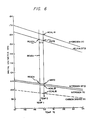
- a constant current in the range of 13 milliamps produces voltage drops across the thermistors in the range of 3.5 volts (for 100% carbon dioxide) to 6.0 volts (for 100% hydrogen) (see Figure 6).
- Voltage readings are slightly scaled by an amplifier 61 to match the characteristics of digital voltmeter 62.
- Voltage readings across the X CELL, H CELL and N CELL thermistors are periodically sampled and sequentially fed to a microcomputer 64.
- microcomputer 64 controls the measurement cycle wherein switch 60 is sequentially connected across X CELL, H CELL and N CELL thermistors. Initial calibration readings utilized in software calculations are stored in nonvolatile memory 66.
- a selector panel 68 provides means for manually inputting to microcomputer 64 the particular binary gas mixture measuring range under evaluation. As shown, selector panel 68 requires the operator to define for microcomputer 64 whether the mixture under analysis comprises "% CO2 in air", % H2 in CO2 ", or "% H2 in air”.
- a local display 70 i.e., at the analyzer instrument, and a remote display 72, e.g., within a central control room, provide the operator with a three digit readout on the percent composition of the binary gas mixture constituents. The third digit is intended primarily to indicate in which direction percent changes are occuring, and is not to absolute accuracy.
- Each X CELL, H CELL and N CELL thermistor is electrically connected, via leads 52, 54 and 56, respectively, to its own constant current regulator 80, 82 and 84, respectively.
- Constant current regulators 80, 82 and 84 each comprise a Burr-Brown XTR110 chip which provides all the elements required to hold the current constant within the thermistors at 13 or 14 milliamps within ⁇ .2 percent.
- an analog multiplexer Connected to the output of constant current regulators 80, 82, and 84, and therefore the cell thermistors, is an analog multiplexer, type 5208, which sequentially samples the voltages across each thermistor.
- a two bit selecting address is supplied by the microcomputer in a pattern that preferably accesses four readings from each cell for averaging, thereby increasing instrument accuracy.
- Buffer amplifier 88 type PM256Z, provides very high impedence loading so that the on resistance of analog multiplexer 86 does not introduce an error into the calculations.
- Voltmeter 62 ( Figure 3) is implemented by an Intersil ICL 7109 integrating digital voltmeter chip, which is a significant element in the operation of the present invention.
- Chip 90 is an integrating dual slope zero correcting type with 12 bit digital output compatible with commercially available microcomputer hardware.
- An input device chip 92 type 74HC373 provides a single chip micrcomputer 94, discussed below, with manually switched input information from selector panel 68 ( Figure 3).
- panel 68 includes three switches which define the range of the binary gas mixture presently under evaluation, information which the software requires to calculate a correct constituent gas compositional percentage.
- the selector panel also contains a switch for defining which of two cell blocks is presently in use. Two cell blocks are desirable for reasons of security, that is, monitoring procedures could continue notwithstanding that a defect develops in one of the blocks, e.g., a reference gas unexpectedly dissipates from a cell resulting in incorrect voltage readings. Different cell blocks produce slightly different calibration measurements which for improved accuracy must each be saved in nonvolatile memory for later recovery and use in percent calculations.
- the selector panel further includes a calibrate switch and three calibration switches, one for each of the three gases encountered, i.e., hydrogen, carbon dioxide and air.
- Each calibration switch operates a solenoid valve which pipes one of the known gases into the measurement cell, X CELL, for a field check of instrument accuracy.
- several additional switches are connected directly to microcomputer 94 via an options dip switch (e.g., "Standard”, “Calibrate D.V.M.”, and "Logout”). These switches are discussed below with reference to Figures 5A and 5B.
- the heart of the analyzer instrument comprises a microcomputer chip 94, e.g., an Intel 8749.
- This chip includes 2K of ROM program storage and 64 bytes of RAM memory for storage of variables, working registers and stack save.
- Nonvolatile memory chip 96, type 9306, contains the calibration standards for each of the two cell blocks. At power reset, the appropriate calibration standards are read into RAM for use in calculating percent concentration. Data transfer is serial with the software generating the required sequence of clock and data.
- Additional system components include a counter 98, type 74HC393, which provides clock means from microcomputer chip 94 to digital voltmeter 90, and a decoder chip 100, type 74HC139, which is connected between micrcomputer 94 and digital voltmeter 90, and which also provides output to a deadman timer 102.
- Timer 102 is a safety device which will automatically reset the micrcomputer should normal activity be disrupted, e.g., as a result of power disturbance.
- Micrcomputer chip 94 provides output via device 106, type 74HC373, to an alarm 108 and identical optical couplers 110 and 112, type 4N33.
- Alarm 108 provides a warning indication should the percent hydrogen in air mixture reach the potentially explosive value of 85%.
- Optocouplers 110 and 112 drive local display 70 and remote display 72, respectively.
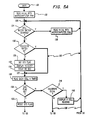
- the controller enters the main loop at 120 "Main”, and proceeds to instruction 122 "Read N.V.M. Into Microcomputer RAM”, which directs initialization of system values following power off reset or first time powering of the instrument. From instruction 122 the controller is directed to junction 123 where it enters the normal processing loop 125, indicated by the bold line in Figures 5A and 5B. During normal operation, all switches on the options dip switch remain “off” and all selector panel switches experience no change.
- the controller proceeds from junction 123 to inquiry 124 "Cell Block Switch Changed?" where the controller determines whether the operator has manually switched from one cell block to the other block, e.g., for repair of the first block. If the cell block switch setting has changed, then the controller deviates from normal loop 125, passing to instruction 128 "Read N.V.M. Into Microcomputer RAM", which directs that standard calibration readings for the new cell block be brought into RAM. As noted above, since different cell blocks do not respond exactly alike, e.g., because thermistors are manufactured only within certain tolerances, standard calibration readings for each cell block are initially taken and separately stored in nonvolatile memory for subsequent recall and use in the calculations described below. From instruction 128 flow is back to junction 123 of normal loop 125.
- Standard calibration of cell values for storage in nonvolatile memory i.e., HCALIB, NCALIB, CCALIB, NSTD and HSTD, described below
- standard calibration values may be obtained and read into nonvolatile memory on-site.
- the Standard Switch is "off” and the controller is directed from inquiry 126 to junction 127, and hence to instruction 136 "Read Each Cell 4 Times” where it measures the voltage across each cell thermistor four times.
- Greater instrument accuracy is obtained by averaging multiple readings, e.g., four, six or eight readings. Also, improved accuracy is believed possible by sequentially reading the voltage across each thermistor as a cycle, and then repeating the cycle four times to obtain the desired number of readings.
- the controller determines whether the "STD" flag has been set, "STD Flag Set?" 138.
- STD Flag is set only when the operator flips the Standard Switch “on”, meaning cell readings are to be collected for storage in nonvolatile memory as standard calibrations.
- inquiry 140 "Calibrate D.V.M.?”, which is a check to determine whether the operator wishes to adjust instrument accuracy by introducing a 100% known gas into X CELL. If the Calibrate D.V.M. dip switch is set, the controller proceeds to instruction 142 "Display X CELL Reading", which provides the operator with visual feedback for manual scaling adjustment of the digital voltmeter 62 ( Figure 3). Again, a "yes" to either inquiry 138 or inquiry 140 directs the controller outside normal loop 125.
- NSTD N CELL standard reading
- HSTD H CELL helium standard reading
- NCALIB X CELL nitrogen calibration reading
- HCALIB X CELL hydrogen calibration reading
- CCALIB X CELL carbon dioxide calibration reading.
- READN present N CELL reading
- READH present H CELL reading
- READX present X CELL reading of binary mixture.
- the appropriate formula is selected by the operator through the binary gas mixture setting on the instrument's selector panel. During normal operation, only the % HYDROGEN IN AIR formula is used to calculate percent gas composition.
- Formulas (1), (2) & (3) each include a correction for measurement cell block temperature change from that temperature at which calibration standards were obtained. Those skilled in the art will recognize that the formulas (1), (2) & (3) can be rewritten for any binary gas mixture under evaluation.
- Logout is a special feature which can be added as an aid to debugging possible trouble within the instrument and to assisting in efforts to increase the instrument' s accuracy. If the Logout Switch is set "yes” then the controller proceeds to "Logout RAM Variables" 150. During normal loop cycling, microcomputer RAM will contain the data used to calculate percent gas concentration to be displayed, e.g., READN, READH, READX, NSTD, HSTD, HCALIB, NCALIB and CCALIB. Activation of the Logout Switch initiates a logout series for either presentation to the display for manual recordation of values, or to a printing device, i.e., if connected to the system.
- each logout delay is incorporated into the display of each variable.
- the normally calculated percent composition is also logged out so a manual calculation using the RAM variables can be conducted to check internal calculations.
- each logout will include the minimum and maximum READH and READN values as a monitor on long term block temperature.
- the controller exits normal loop 125 at inquiry 126 if the operator has set the Standard Switch "on”, meaning that read values are to be stored as calibration standards in nonvolatile memory for future reference. If “on”, flow proceeds to direction 130 "Set STD Flag” and hence to instruction 132 "Display STADRD". STADRD is displayed as visual feedback to the operator that the instrument is functioning properly by acknowledging the Standard Switch setting. After instruction 132, the controller delays action for 60 seconds “Delay 60 Sec” 134 to allow the operator time to purge and fill the X CELL with a known gas. Cell readings are then taken four times 136 "Read Each Cell 4 Times".
- Inquiry 154 is simply a software double check against possible human error in that for standard calibration readings to be stored in nonvolatile memory, both the Standard Switch and the Calibration Switch must be set. If the Calibration Switch is "off”, the controller is directed to instruction 156 “Display ERROR” and hence to hold operations, "HOLD” 158. At this point, the operator must recheck his switch settings to uncover the source of the error, and reset the computer, whereupon the controller reenters the software at "Main" 120.
- the controller proceeds to instructions 160, 162 and 164 to "Store X CELL Value In N.V.M.”, "Store N CELL Value In N.V.M.”, and "Store H CELL Value In N.V.M.”, respectively. Since several minutes are required to calibrate each gas, i.e., hydrogen, nitrogen and carbon dioxide, a slight correction may be desirable depending upon the temperature change from the previous calibration of a standard.
- Figure 6 graphically illustrates how calibration standards, i.e., HSTD, NSTD, HCALIB, NCALIB and CCALIB, change with temperature about a substantially constant block temperature of 50° Celsius.
- Figure 6 constructed from empirical data, is a plot of digital voltmeter readings for the given gases versus temperature. Correction of voltage readings as a function of temperature can be easily accomplished using READH, READN, HSTD and NSTD readings and simple proportional arithmetic. Also, greater accuracy in the resultant calculations is believed obtainable by serially storing calibration standards, HSTD, NSTD, HCALIB, NCALIB, and CCALIB, with the least important gas stored first and the most important last. Thus, a preferred order of calibration for turbo generation monitoring is to sequentially store CCALIB, NCALIB and then HCALIB. The last N CELL and H CELL values are those ultimately stored in nonvolatile memory as NSTD and HSTD, respectively.
- One procedure for recording calibration standards comprises: allow instrument to reach stabilization temperature; introduce a known 100% carbon dioxide gas into the measurement cell; measure and store the voltage across X CELL thermistor as carbon dioxide calibration standard reading (CCALIB); introduce a known 100% nitrogen gas into the measurement cell; measure and store the voltage across X CELL thermistor as the nitrogen calibration standard reading (NCALIB); introduce a known 100% hydrogen gas into the measurement cell; and measure and store the voltage across the X CELL thermistor as the hydrogen calibration standard reading (HCALIB).
- the voltage drops across the N Cell and H Cell thermistors are automatically measured and store as NSTD and HSTD, respectively, with the recordation of a calibration standard.
- the controller is directed to display the X CELL thermistor reading, "Display X CELL Reading” 166, which is simply visual feedback for the operator that an appropriate value is being read and stored into nonvolatile memory as CCALIB, NCALIB or HCALIB. Thereafter the controller is directed at inquiry 168 "Standard Switch Set?" to again check the Standard Switch setting, this time to verify that the operator has switched “off” the Standard Switch after the calibration standard has been recorded. Once confirmed, the controller returns to normal operating loop 125 via junction 123.
- HSTD and NSTD are near opposite ends of the range of possible voltage readings (defined by HCALIB and NCALIB) for a hydrogen and air binary gas mixture.
Landscapes
- Physics & Mathematics (AREA)
- Health & Medical Sciences (AREA)
- Life Sciences & Earth Sciences (AREA)
- Chemical & Material Sciences (AREA)
- Analytical Chemistry (AREA)
- Biochemistry (AREA)
- General Health & Medical Sciences (AREA)
- General Physics & Mathematics (AREA)
- Immunology (AREA)
- Pathology (AREA)
- Investigating Or Analyzing Materials By The Use Of Electric Means (AREA)
- Investigating Or Analyzing Materials Using Thermal Means (AREA)
Applications Claiming Priority (3)
| Application Number | Priority Date | Filing Date | Title |
|---|---|---|---|
| US07/194,635 US4891629A (en) | 1988-05-16 | 1988-05-16 | Binary gas analyzer instrument and analysis method |
| US194635 | 1988-05-16 | ||
| CA000601475A CA1323508C (en) | 1988-05-16 | 1989-06-01 | Binary gas analyzer instrument and analysis method |
Publications (2)
| Publication Number | Publication Date |
|---|---|
| EP0342901A2 true EP0342901A2 (de) | 1989-11-23 |
| EP0342901A3 EP0342901A3 (de) | 1990-11-22 |
Family
ID=25672777
Family Applications (1)
| Application Number | Title | Priority Date | Filing Date |
|---|---|---|---|
| EP19890304892 Withdrawn EP0342901A3 (de) | 1988-05-16 | 1989-05-15 | Analysegerät für binäre Gasmischungen und Analyseverfahren |
Country Status (4)
| Country | Link |
|---|---|
| US (1) | US4891629A (de) |
| EP (1) | EP0342901A3 (de) |
| JP (1) | JPH01321352A (de) |
| CA (1) | CA1323508C (de) |
Cited By (6)
| Publication number | Priority date | Publication date | Assignee | Title |
|---|---|---|---|---|
| EP0431394A3 (en) * | 1989-12-07 | 1992-01-22 | Siemens Aktiengesellschaft | Method and apparatus for gas analysis |
| FR2749660A1 (fr) * | 1996-06-10 | 1997-12-12 | United Kingdom Government | Procede et appareil de mesure de la temperature et de la composition d'un melange de gaz |
| FR2750500A1 (fr) * | 1996-06-28 | 1998-01-02 | Ind De Construction D App Et R | Capteur de gaz hydrogene |
| EP2559489A1 (de) * | 2010-11-24 | 2013-02-20 | Fraunhofer-Gesellschaft zur Förderung der angewandten Forschung e.V. | Mikrofluidisches System mit Temperierung und Verfahren zur Temperierung in einem mikrofluidischen System |
| US8551299B2 (en) | 2009-05-29 | 2013-10-08 | Deeya Energy, Inc. | Methods of producing hydrochloric acid from hydrogen gas and chlorine gas |
| US8877365B2 (en) | 2009-05-28 | 2014-11-04 | Deeya Energy, Inc. | Redox flow cell rebalancing |
Families Citing this family (13)
| Publication number | Priority date | Publication date | Assignee | Title |
|---|---|---|---|---|
| US5590651A (en) * | 1995-01-17 | 1997-01-07 | Temple University - Of The Commonwealth System Of Higher Education | Breathable liquid elimination analysis |
| US5793296A (en) * | 1996-04-30 | 1998-08-11 | Lewkowicz; Mike | Apparatus for carbon monoxide detection and automatic shutoff of a heating system |
| US6148659A (en) * | 1998-10-08 | 2000-11-21 | Traina; John E. | Gas concentration monitor having a bridge configured flow system |
| US6942943B2 (en) * | 2003-02-10 | 2005-09-13 | Fuelcell Energy, Inc. | Catalyst and/or electrolyte loaded plate and method of making same |
| US7550113B2 (en) * | 2004-09-16 | 2009-06-23 | Proton Energy Systems, Inc. | System for maintaining hydrogen purity in electrical generators and method thereof |
| US20060057727A1 (en) * | 2004-09-16 | 2006-03-16 | Speranza A J | System for monitoring the health of electrical generators and method thereof |
| CN101421600B (zh) * | 2006-04-11 | 2011-11-30 | 萨索特兰公司 | 用于校准分布式纤维温度感测系统的方法和装置 |
| US20110079074A1 (en) * | 2009-05-28 | 2011-04-07 | Saroj Kumar Sahu | Hydrogen chlorine level detector |
| EP3265766B1 (de) | 2015-03-05 | 2023-09-27 | Honeywell International Inc. | Verwendung ausgewählter glastypen und glasdicken im optischen pfad zur beseitigung von querempfindlichkeit auf wasserabsorptionsspitzen |
| CN108351293A (zh) | 2015-09-10 | 2018-07-31 | 霍尼韦尔国际公司 | 具有归一化响应和改进灵敏度的气体检测器 |
| WO2017062626A1 (en) | 2015-10-09 | 2017-04-13 | Honeywell International Inc. | Electromagnetic radiation detector using a planar golay cell |
| US9606049B1 (en) * | 2015-10-09 | 2017-03-28 | Honeywell International Inc. | Gas detector using a golay cell |
| CN109164134B (zh) * | 2018-10-22 | 2023-11-28 | 洛阳三隆安装检修有限公司 | 一种提高热导式氢气分析仪分析准确度的系统 |
Family Cites Families (16)
| Publication number | Priority date | Publication date | Assignee | Title |
|---|---|---|---|---|
| DE594696C (de) * | 1931-05-13 | 1934-03-21 | Siemens & Halske Akt Ges | Elektrischer Gaspruefer, bei welchem die Widerstandsaenderungen eines vom Pruefgas umspuelten Messdrahtes und eines in einem Vergleichsgas befindlichen zweiten Messdrahtes gemessen werden |
| US2326884A (en) * | 1941-11-28 | 1943-08-17 | Weaver Mfg Co | Gas analyzer |
| US2591762A (en) * | 1946-06-14 | 1952-04-08 | Nina D Zaikowsky | Gas analysis apparatus |
| GB943550A (en) * | 1959-12-08 | 1963-12-04 | Gas Council | Improvements in or relating to thermal conductivity detector assemblies |
| GB966042A (en) * | 1961-03-21 | 1964-08-06 | Union Carbide Corp | Improvements in or relating to methods for thermistor matching |
| US3680359A (en) * | 1968-05-02 | 1972-08-01 | Mc Graw Edison Co | Transformer having incipient fault detector |
| GB1387412A (en) * | 1971-07-07 | 1975-03-19 | English Electric Valve Co Ltd | Combustible gas detectors |
| US3895630A (en) * | 1973-06-04 | 1975-07-22 | Del Mar Eng Lab | Respiratory gas analyzer including a carbon dioxide and respiratory quotient computer |
| US3961900A (en) * | 1973-06-05 | 1976-06-08 | Catalytic Pollution Controls, Inc. | Combustible vapor detector |
| US4164862A (en) * | 1977-11-25 | 1979-08-21 | Jackson Milton L | Multicomponent thermal conductivity analyzer |
| FR2416467A1 (fr) * | 1978-02-03 | 1979-08-31 | Ici Ltd | Procede et appareil pour l'analyse de gaz |
| GB2091882B (en) * | 1981-01-26 | 1985-05-01 | Nat Res Dev | Electrical catalytic gas detection systems |
| DE3132297C2 (de) * | 1981-08-12 | 1985-05-15 | Auergesellschaft Gmbh, 1000 Berlin | Schaltungsanordnung für ein Gerät zur Messung und Anzeige der Konzentration von in Luft enthaltenen brennbaren Gasen und Dämpfen |
| FR2556098B1 (fr) * | 1983-12-06 | 1990-05-11 | Sumitomo Light Metal Ind | Appareil de mesure de la concentration en hydrogene dissous dans un metal en fusion |
| US4562723A (en) * | 1984-07-27 | 1986-01-07 | Hubner Hans J | Method of and apparatus for the measurement of subterranean atmospheric parameters |
| US4847783A (en) * | 1987-05-27 | 1989-07-11 | Richard Grace | Gas sensing instrument |
-
1988
- 1988-05-16 US US07/194,635 patent/US4891629A/en not_active Expired - Fee Related
-
1989
- 1989-04-17 JP JP1095468A patent/JPH01321352A/ja active Pending
- 1989-05-15 EP EP19890304892 patent/EP0342901A3/de not_active Withdrawn
- 1989-06-01 CA CA000601475A patent/CA1323508C/en not_active Expired - Fee Related
Cited By (6)
| Publication number | Priority date | Publication date | Assignee | Title |
|---|---|---|---|---|
| EP0431394A3 (en) * | 1989-12-07 | 1992-01-22 | Siemens Aktiengesellschaft | Method and apparatus for gas analysis |
| FR2749660A1 (fr) * | 1996-06-10 | 1997-12-12 | United Kingdom Government | Procede et appareil de mesure de la temperature et de la composition d'un melange de gaz |
| FR2750500A1 (fr) * | 1996-06-28 | 1998-01-02 | Ind De Construction D App Et R | Capteur de gaz hydrogene |
| US8877365B2 (en) | 2009-05-28 | 2014-11-04 | Deeya Energy, Inc. | Redox flow cell rebalancing |
| US8551299B2 (en) | 2009-05-29 | 2013-10-08 | Deeya Energy, Inc. | Methods of producing hydrochloric acid from hydrogen gas and chlorine gas |
| EP2559489A1 (de) * | 2010-11-24 | 2013-02-20 | Fraunhofer-Gesellschaft zur Förderung der angewandten Forschung e.V. | Mikrofluidisches System mit Temperierung und Verfahren zur Temperierung in einem mikrofluidischen System |
Also Published As
| Publication number | Publication date |
|---|---|
| JPH01321352A (ja) | 1989-12-27 |
| CA1323508C (en) | 1993-10-26 |
| US4891629A (en) | 1990-01-02 |
| EP0342901A3 (de) | 1990-11-22 |
Similar Documents
| Publication | Publication Date | Title |
|---|---|---|
| US4891629A (en) | Binary gas analyzer instrument and analysis method | |
| Roder | A transient hot wire thermal conductivity apparatus for fluids | |
| US4766763A (en) | Gas leak detection apparatus and methods | |
| EP0293255A2 (de) | Gerät zur Detektion von Gasen | |
| US3059471A (en) | Calorimeter | |
| Kosky et al. | Pool boiling heat transfer to cryogenic liquids; I. Nucleate regime data and a test of some nucleate boiling correlations | |
| WO1980000878A1 (en) | A differential calorimeter based on the heat leak principle | |
| Wormald et al. | The excess enthalpies of hydrogen+ methane, hydrogen+ nitrogen, methane+ nitrogen, methane+ argon, and nitrogen+ argon at 298 and 201 K at pressures up to 10.2 MPa | |
| NO302320B1 (no) | Fremgangsmåte og apparat for bestemmelse av varmeledningsevnen for gasser | |
| US5305231A (en) | Multiple K factor, selectable gas detector | |
| US5428985A (en) | Gas leak detection apparatus and methods | |
| JPH06207913A (ja) | 熱硬化性合成樹脂の時間/温度計測用熱量計 | |
| Furukawa | Vapor Pressures of Natural Neon and of the Isotopes 20Ne and 22Ne from the Triple Point to the Normal Boiling Point | |
| US3500675A (en) | Apparatus for an automatic gravimetric recording of characteristic curves which represent the sorption of gas by a sample | |
| Challoner et al. | An electrically calibrated bomb calorimeter | |
| Morrison et al. | AN ADIABATIC CALORIMETER FOR THE TEMPERATURE REGION BELOW 20° K.—THE SPECIFIC HEAT OF SODIUM CHLORIDE | |
| CN1021085C (zh) | 二元气体分析仪及分析方法 | |
| Arntz | New high pressure low temperature differential scanning calorimeter | |
| Bennett et al. | AN ADIABATIC SOLUTION CALORIMETER USED FOR MEASURING THE MOLAR EXCESS ENTHALPY OF THE SYSTEM CARBON TETRACHLORIDE–BENZENE AT 25° C | |
| Oriani et al. | The heat capacity of chromium carbide (Cr3C2) | |
| Svec et al. | A recording mercurial manometer for the pressure range 0–760 mm of mercury | |
| US5621161A (en) | Method for monitoring for the presence of dissolved gas in a fluid under pressure | |
| Anderson et al. | Characteristics of germanium resistance thermometers from 1 to 35 K and the ISU magnetic temperature scale | |
| Kemper et al. | Temperature measurements | |
| Zhi-Cheng et al. | An adiabatic calorimeter for heat capacity measurements in the temperature range 300–600 K and pressure range 0.1–15 MPa |
Legal Events
| Date | Code | Title | Description |
|---|---|---|---|
| PUAI | Public reference made under article 153(3) epc to a published international application that has entered the european phase |
Free format text: ORIGINAL CODE: 0009012 |
|
| AK | Designated contracting states |
Kind code of ref document: A2 Designated state(s): CH DE FR GB IT LI SE |
|
| PUAL | Search report despatched |
Free format text: ORIGINAL CODE: 0009013 |
|
| AK | Designated contracting states |
Kind code of ref document: A3 Designated state(s): CH DE FR GB IT LI SE |
|
| 17P | Request for examination filed |
Effective date: 19901217 |
|
| 17Q | First examination report despatched |
Effective date: 19920602 |
|
| STAA | Information on the status of an ep patent application or granted ep patent |
Free format text: STATUS: THE APPLICATION IS DEEMED TO BE WITHDRAWN |
|
| 18D | Application deemed to be withdrawn |
Effective date: 19930518 |