EP0342870B1 - Yarn texturing machine - Google Patents
Yarn texturing machine Download PDFInfo
- Publication number
- EP0342870B1 EP0342870B1 EP19890304809 EP89304809A EP0342870B1 EP 0342870 B1 EP0342870 B1 EP 0342870B1 EP 19890304809 EP19890304809 EP 19890304809 EP 89304809 A EP89304809 A EP 89304809A EP 0342870 B1 EP0342870 B1 EP 0342870B1
- Authority
- EP
- European Patent Office
- Prior art keywords
- yarn
- feed
- yarns
- fluid jet
- feed means
- Prior art date
- Legal status (The legal status is an assumption and is not a legal conclusion. Google has not performed a legal analysis and makes no representation as to the accuracy of the status listed.)
- Expired - Lifetime
Links
- 239000012530 fluid Substances 0.000 claims description 40
- 238000010438 heat treatment Methods 0.000 claims description 14
- 238000009736 wetting Methods 0.000 claims description 12
- 238000011144 upstream manufacturing Methods 0.000 claims description 6
- XLYOFNOQVPJJNP-UHFFFAOYSA-N water Substances O XLYOFNOQVPJJNP-UHFFFAOYSA-N 0.000 claims description 4
- 230000000694 effects Effects 0.000 description 4
- 239000004753 textile Substances 0.000 description 3
- 230000002093 peripheral effect Effects 0.000 description 2
- 238000000926 separation method Methods 0.000 description 2
- 239000004952 Polyamide Substances 0.000 description 1
- 239000004743 Polypropylene Substances 0.000 description 1
- 230000001154 acute effect Effects 0.000 description 1
- 229910010293 ceramic material Inorganic materials 0.000 description 1
- 239000002131 composite material Substances 0.000 description 1
- 230000006866 deterioration Effects 0.000 description 1
- 238000010586 diagram Methods 0.000 description 1
- 239000007788 liquid Substances 0.000 description 1
- 239000000463 material Substances 0.000 description 1
- 238000000034 method Methods 0.000 description 1
- 229920002647 polyamide Polymers 0.000 description 1
- 229920000728 polyester Polymers 0.000 description 1
- -1 polypropylene Polymers 0.000 description 1
- 229920001155 polypropylene Polymers 0.000 description 1
- 239000007921 spray Substances 0.000 description 1
- 229920002554 vinyl polymer Polymers 0.000 description 1
Images


Classifications
-
- D—TEXTILES; PAPER
- D02—YARNS; MECHANICAL FINISHING OF YARNS OR ROPES; WARPING OR BEAMING
- D02G—CRIMPING OR CURLING FIBRES, FILAMENTS, THREADS, OR YARNS; YARNS OR THREADS
- D02G1/00—Producing crimped or curled fibres, filaments, yarns, or threads, giving them latent characteristics
- D02G1/16—Producing crimped or curled fibres, filaments, yarns, or threads, giving them latent characteristics using jets or streams of turbulent gases, e.g. air, steam
- D02G1/168—Producing crimped or curled fibres, filaments, yarns, or threads, giving them latent characteristics using jets or streams of turbulent gases, e.g. air, steam including drawing or stretching on the same machine
Definitions
- This invention relates to yarn texturing machines, and in particular to textile machines for the texturing of yarns by means of fluid jets.
- Textile machines are known in which one or more yarns are fed in single, parallel or core/effect form to a fluid jet in which the turbulent fluid serves to cause the filaments of the yarns to form loops, thereby producing a bulky single or composite yarn suitable for various textile applications.
- a yarn wetting device may be located immediately upstream of the fluid jet, acting on some or all of the yarns, and in such cases the yarn wetting device and the fluid jet are customarily housed in a common housing or "jet-box".
- parallel and, more especially,core/effect arrangements in order to ensure acceptable texturing of the yarn, it is necessary that any yarn which runs through the wetting device is kept apart from the other yarn or yarns until they come together in the fluid jet itself.
- the invention provides a yarn texturing machine comprising a fluid jet texturing means for a plurality of yarns to form a textured yarn and respective feed means for each of said yarns, whereby each of said feed means is disposed in said machine relative to the other feed means and said fluid jet texturing means so as to feed the respective yarn along a substantially straight yarn path from said feed means to said fluid jet texturing means, which yarn path is spaced from the path of the other yarn or yarns but converges therewith within said fluid jet texturing means at an angle of between 70° and 60° to each other. Said paths may converge at an angle of substantially 65°.
- the plane containing said yarn paths may be inclined to the axis of said jet at an angle of between 60° and 90°, preferably at substantially 70°.
- Each of said feed means may comprise a pair of feed rollers providing a nip therebetween through which the respective yarn may travel. One roller of each of said pairs of feed rollers may be driven in rotation.
- said machine may comprise respective first feed means operable to forward said yarn to said respective feed means at a speed less than that at which said yarn is fed to said fluid jet texturing means, whereby said yarn is drawn between said first feed means and said respective,drawing, feed means.
- Each of said first feed means may comprise a pair of first feed rollers providing a nip therebetween through which the respective yarn may travel. One roller of each of said pairs of first feed rollers may be driven in rotation.
- Heating means for each of said yarns may be provided between the respective first feed means and the respective drawing feed means, and said heating means may comprise a plate, pin or roller.
- a common heating means may be provided for said plurality of yarns, and said heating means may be electrical heating means or may be vapour phase heating means.
- Said machine may comprise a creel, whereby said first feed means are operable to withdraw said yarns form respective supplies thereof mounted in said creel.
- Said machine may comprise a main frame spaced from said creel and on which said fluid jet texturing means, said drawing feed means and said first feed means are mounted, said first feed means withdrawing said yarns from said supplies thereof along feed paths extending above an operator's aisle disposed between said creel and said main frame.
- the machine may also comprise yarn wetting means which may be disposed adjacent but upstream of said fluid jet texturing means.
- Said wetting means may comprise means adapted to apply water to at least one of said yarns, in which case said wetting means may be disposed so as to apply water to a yarn forming a core yarn of said textured yarn.
- Said machine may comprise wind-up means, which may be mounted in said main frame beneath said fluid jet texturing means. Said feed means and said wind up means may be driven by respective drive shafts extending longitudinally of said machine.
- Said machine may also comprise further treatment means, such as heating means, which may comprise an elongate contact heater mounted on said main frame above said fluid jet texturing means to extend upwardly therefrom.
- Said further treatment heating means may also comprise turnround yarn guide means around which said textured yarn may pass between an upwards and a downwards passage over said heating means.
- Said turnround guide means may be mounted on said further treatment heater to be movable longitudinally thereof between a threading location at the lower end of said further treatment heater and an operating location at the upper end of said further treatment heater.
- Said turnround guide means may be mounted on a sledge.
- Said further treatment heating means may comprise a heater plate having a pair of substantially parallel grooves therein extending from said lower end to said upper end of said heater.
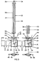
- the texturing section 21 is shown in greater detail in Figs 2 and 3, and comprises a "box" or housing 23 which is mounted on the main frame 11 and in which is mounted a fluid jet 24 such as an air jet.
- the relative disposition of the drawing feed means 19, 20 and the fluid jet 24 is such that the yarns 15, 16 are fed from the former to the latter along spaced respective, substantially straight paths, which converge with each other within the fluid jet 24, the plane of the yarn paths being inclined to the axis A of the fluid jet 24 at an angled ⁇ of between 60° and 90°, preferably substantially 70°, as shown in Fig 3.
- the yarn paths converge at an angle ⁇ of between 70° and 60°, for example substantially 65°, as shown in Fig 2, thereby ensuring optimum control of the yarns in this low tension region and good quality of textured yarn at completion of texturing.
- the wetting means 25 is preferably of the type described in British Patent No 2171931 which applies liquid to the core or wetted yarn 15, without it deviating substantially from a straight yarn path from the drawing feed means 20 to the fluid jet 24. In this particular case water from a supply 26 thereof is fed to a manifold 27 and then to the applicator head 28.
- the wetted yarn 15, and the yarn 16 are fed into the fluid jet 24, to which air or other fluid from a supply 29 thereof is also fed.
- the yarns 15, 16 are textured and combined to form a single textured yarn 30 which issues from the fluid jet 24 and is guided through a guide 31, upwardly out of the box or housing 23.
- Third feed means 32 driven by drive shaft 44 forwards the textured yarn 30 from the fluid jet 24 to a further treatment or setting heater 33 which extends upwardly above the texturing section 21.
- the third feed means 32 also comprises a roller driven by drive shaft 44 and a freely rotatable roller forming a nip therewith through which the yarn 30 may pass.
- the driven roller of the of the third feed means 32 may be driven so as to have a peripheral speed less than that of the driven rollers of the drawing feed means 19, 20 so that the yarns 15, 16 are overfed into the texturing section 21 if desired.
- the textured yarn 30 passes around a "turnround" guide 34 mounted on a sledge 35 which is itself mounted on the heater 33 so as to be movable longitudinally thereof between a threading position at the lower end of heater 33 (shown in dashed lines in Fig 2) and an operating position at the upper end of the heater 33 (shown in full lines in Figs 1 and 2).
- the yarn 30 makes an upward and then a downward passage over the further treatment heater 33, passing in contact therewith along a groove 37 on its upward journey and groove 38 on its downward journey.
- the grooves 37, 38 are substantially parallel and extend from the lower end of the heater plate 39 of heater 33 to the upper end thereof.
- the yarn 30 is fed downwardly by fourth feed means 45 to wind up means 36 mounted on the main frame 11 in three rows, one above the other beneath the texturing section 21.
- the fourth feed means 45 and the wind-up means 36 are driven by respective drive shafts 46, 47 extending longitudinally of the machine 10.
- wetting means 25 for both yarns may be provided, and the wetting means 25 may be disposed outside of the housing 23 if preferred, the housing 23 being provided around the fluid jet 24 to contain spray issuing therefrom due to the action of the fluid jet on the wet yarn.
- the textured yarn 30 may be drawn from the housing 23 in a downwards direction to a further treatment heater 33 disposed in the main frame 11 beneath the texturing section 21 and behind the wind-up means 36, although such an arrangement may limit the length of the heater 33 and therefore the amount of further treatment received by the yarn 30.
- first feed means and drawing feed means for the two yarns 15, 16 enables different draw ratios to be applied to the two yarns and different feed rates to the texturing section 21.
- separate draw pins or rollers 22 may be provided if desired, particularly if the drawing temperature for the two yarns is to be different.
- the yarns 15, 16 may pass around differing diameter parts of the same feed roller for the purpose of providing differing feed speeds and/or draw ratios.
- the relative position of the fluid jet 24 and the drawing feed means 19, 20 may be adjustable so as to vary the angle of convergence of the two yarns 15, 16 if desired.
- any one or each of the feed means 17, 18, 19, 20, 32, 45 may be replaced by a roller / apron, double apron or capstan feed device if desired, each driven by a respective drive shaft extending longitudinally of the machine and common to the appropriate feed means of all the yarn processing stations.
- the further treatment heaters 33 for each yarn processing station may be connected as part of a multi-station heater, for example by means of an elongate boiler extending longitudinally of the machine 10 of a vapour phase heater.
- the jet 24, or at least such yarn contacting parts thereof are of a ceramic material.
- the use of such a material enables the yarns 15, 16 to enter the jet 24 under tension at the angle of between 60° and 90° to the axis A of the jet 24 without undue wear on the entry part of the jet 24.
Landscapes
- Engineering & Computer Science (AREA)
- Physics & Mathematics (AREA)
- Fluid Mechanics (AREA)
- Mechanical Engineering (AREA)
- Textile Engineering (AREA)
- Yarns And Mechanical Finishing Of Yarns Or Ropes (AREA)
Description
- This invention relates to yarn texturing machines, and in particular to textile machines for the texturing of yarns by means of fluid jets.
- Textile machines are known in which one or more yarns are fed in single, parallel or core/effect form to a fluid jet in which the turbulent fluid serves to cause the filaments of the yarns to form loops, thereby producing a bulky single or composite yarn suitable for various textile applications. To facilitate this process a yarn wetting device may be located immediately upstream of the fluid jet, acting on some or all of the yarns, and in such cases the yarn wetting device and the fluid jet are customarily housed in a common housing or "jet-box". With parallel and, more especially,core/effect arrangements, in order to ensure acceptable texturing of the yarn, it is necessary that any yarn which runs through the wetting device is kept apart from the other yarn or yarns until they come together in the fluid jet itself. If this is not done, entanglement of the filaments of the yarns can take place upstream of the fluid jet, and this prevents or inhibits the texturing of the yarn. To prevent such prior entanglement it is usual to have guides for the two yarns at the entry of the jet-box and also on the body of the jet itself. These guides, whilst keeping the paths of the yarns separate, also provide changes in direction of travel of the yarns, with consequential increases in yarn tension as a yarn travels around a guide. Hence the yarn tensions prior to entry to the jet box may be considerably less than those at entry to the jet itself. Since the tensioning effect of the fluid jet reduces as the yarn throughput speed increases an upper limit of yarn throughput speed occurs when the yarn tensions upstream of the jet box input guides fall to a level at which threadline instability occurs. To avoid such a problem it is known to feed the two yarns in spaced but converging straight yarn paths from the feed means to the air jet, for example in US Patent No 4608814. Such an arrangement eliminates the change in yarn tension along the yarn path. In this prior patent the angular separation of the yarns is specified as being acute, more specifically as being less than 60° (cf. claim 14), usually less than 45°, preferably less than 30° and more preferably from 8° to 25°. However at current high processing speeds the tensions upstream of the air jet are low and it has been found that the abovementioned entanglement of the yarns can occur with such an arrangement. It has also been found that too large an angular separation of the converging yarns leads to a deterioration in the quality of the resulting textured yarn.
- It is an object of the present invention to provide a yarn texturing machine which avoids, at least to a substantial extent, the abovementioned disadvantages, and which ensures adequate control of the yarn throughout its passage through the machine.
- The invention provides a yarn texturing machine comprising a fluid jet texturing means for a plurality of yarns to form a textured yarn and respective feed means for each of said yarns, whereby each of said feed means is disposed in said machine relative to the other feed means and said fluid jet texturing means so as to feed the respective yarn along a substantially straight yarn path from said feed means to said fluid jet texturing means, which yarn path is spaced from the path of the other yarn or yarns but converges therewith within said fluid jet texturing means at an angle of between 70° and 60° to each other. Said paths may converge at an angle of substantially 65°. The plane containing said yarn paths may be inclined to the axis of said jet at an angle of between 60° and 90°, preferably at substantially 70°.
- Each of said feed means may comprise a pair of feed rollers providing a nip therebetween through which the respective yarn may travel. One roller of each of said pairs of feed rollers may be driven in rotation. For each of said yarns said machine may comprise respective first feed means operable to forward said yarn to said respective feed means at a speed less than that at which said yarn is fed to said fluid jet texturing means, whereby said yarn is drawn between said first feed means and said respective,drawing, feed means. Each of said first feed means may comprise a pair of first feed rollers providing a nip therebetween through which the respective yarn may travel. One roller of each of said pairs of first feed rollers may be driven in rotation.
- Heating means for each of said yarns may be provided between the respective first feed means and the respective drawing feed means, and said heating means may comprise a plate, pin or roller. A common heating means may be provided for said plurality of yarns, and said heating means may be electrical heating means or may be vapour phase heating means.
- Said machine may comprise a creel, whereby said first feed means are operable to withdraw said yarns form respective supplies thereof mounted in said creel. Said machine may comprise a main frame spaced from said creel and on which said fluid jet texturing means, said drawing feed means and said first feed means are mounted, said first feed means withdrawing said yarns from said supplies thereof along feed paths extending above an operator's aisle disposed between said creel and said main frame.
- The machine may also comprise yarn wetting means which may be disposed adjacent but upstream of said fluid jet texturing means. Said wetting means may comprise means adapted to apply water to at least one of said yarns, in which case said wetting means may be disposed so as to apply water to a yarn forming a core yarn of said textured yarn.
- Said machine may comprise wind-up means, which may be mounted in said main frame beneath said fluid jet texturing means. Said feed means and said wind up means may be driven by respective drive shafts extending longitudinally of said machine. Said machine may also comprise further treatment means, such as heating means, which may comprise an elongate contact heater mounted on said main frame above said fluid jet texturing means to extend upwardly therefrom. Said further treatment heating means may also comprise turnround yarn guide means around which said textured yarn may pass between an upwards and a downwards passage over said heating means. Said turnround guide means may be mounted on said further treatment heater to be movable longitudinally thereof between a threading location at the lower end of said further treatment heater and an operating location at the upper end of said further treatment heater. Said turnround guide means may be mounted on a sledge. Said further treatment heating means may comprise a heater plate having a pair of substantially parallel grooves therein extending from said lower end to said upper end of said heater.
- The invention will now be further described with reference to the accompanying drawings in which :-
- Fig 1 is a threadline diagram of a machine in accordance with the invention
- Fig 2 is a sectional view of part of the machine of Fig 1 to an enlarged scale, and
- Fig 3 is a front view of the part of the machine of Fig 2.
- The
texturing section 21 is shown in greater detail in Figs 2 and 3, and comprises a "box" orhousing 23 which is mounted on themain frame 11 and in which is mounted afluid jet 24 such as an air jet. The relative disposition of the drawing feed means 19, 20 and thefluid jet 24 is such that theyarns fluid jet 24, the plane of the yarn paths being inclined to the axis A of thefluid jet 24 at an angled β of between 60° and 90°, preferably substantially 70°, as shown in Fig 3. Preferably the yarn paths converge at an angle α of between 70° and 60°, for example substantially 65°, as shown in Fig 2, thereby ensuring optimum control of the yarns in this low tension region and good quality of textured yarn at completion of texturing. Between thedrawing feed rollers fluid jet 24 is wetting means 25. The wetting means 25 is preferably of the type described in British Patent No 2171931 which applies liquid to the core or wettedyarn 15, without it deviating substantially from a straight yarn path from the drawing feed means 20 to thefluid jet 24. In this particular case water from asupply 26 thereof is fed to amanifold 27 and then to theapplicator head 28. The wettedyarn 15, and theyarn 16 are fed into thefluid jet 24, to which air or other fluid from asupply 29 thereof is also fed. In thefluid jet 24 theyarns textured yarn 30 which issues from thefluid jet 24 and is guided through aguide 31, upwardly out of the box orhousing 23. Third feed means 32 driven bydrive shaft 44 forwards thetextured yarn 30 from thefluid jet 24 to a further treatment or settingheater 33 which extends upwardly above thetexturing section 21. The third feed means 32 also comprises a roller driven bydrive shaft 44 and a freely rotatable roller forming a nip therewith through which theyarn 30 may pass. The driven roller of the of the third feed means 32 may be driven so as to have a peripheral speed less than that of the driven rollers of the drawing feed means 19, 20 so that theyarns texturing section 21 if desired. Thetextured yarn 30 passes around a "turnround"guide 34 mounted on asledge 35 which is itself mounted on theheater 33 so as to be movable longitudinally thereof between a threading position at the lower end of heater 33 (shown in dashed lines in Fig 2) and an operating position at the upper end of the heater 33 (shown in full lines in Figs 1 and 2). With thesledge 35 in the operation position, theyarn 30 makes an upward and then a downward passage over thefurther treatment heater 33, passing in contact therewith along agroove 37 on its upward journey andgroove 38 on its downward journey. Thegrooves heater plate 39 ofheater 33 to the upper end thereof. From the lower end ofheater 33, theyarn 30 is fed downwardly by fourth feed means 45 to wind up means 36 mounted on themain frame 11 in three rows, one above the other beneath thetexturing section 21. The fourth feed means 45 and the wind-up means 36 are driven byrespective drive shafts machine 10. - Other embodiments of texturing machine in accordance with the invention will be readily apparent to persons skilled in the art. For example wetting means 25 for both yarns may be provided, and the wetting means 25 may be disposed outside of the
housing 23 if preferred, thehousing 23 being provided around thefluid jet 24 to contain spray issuing therefrom due to the action of the fluid jet on the wet yarn. Also if preferred thetextured yarn 30 may be drawn from thehousing 23 in a downwards direction to afurther treatment heater 33 disposed in themain frame 11 beneath thetexturing section 21 and behind the wind-up means 36, although such an arrangement may limit the length of theheater 33 and therefore the amount of further treatment received by theyarn 30. The provision of separate first feed means and drawing feed means for the twoyarns texturing section 21. As an alternative to the embodiment shown separate draw pins orrollers 22 may be provided if desired, particularly if the drawing temperature for the two yarns is to be different. However as a further alternative theyarns fluid jet 24 and the drawing feed means 19, 20 may be adjustable so as to vary the angle of convergence of the twoyarns further treatment heaters 33 for each yarn processing station, shown separately in Fig 3, may be connected as part of a multi-station heater, for example by means of an elongate boiler extending longitudinally of themachine 10 of a vapour phase heater. - In order that the yarn contacting parts of the jet have a usefully long working life whilst being subjected to the abrading action of the yarn, the
jet 24, or at least such yarn contacting parts thereof, are of a ceramic material. The use of such a material enables theyarns jet 24 under tension at the angle of between 60° and 90° to the axis A of thejet 24 without undue wear on the entry part of thejet 24.
Claims (10)
- A yarn texturing machine (10) comprising a fluid jet texturing means (24) for a plurality of yarns (15, 16) to form a textured yarn (30) and respective feed means (19, 20) for each of said yarns (15, 16), whereby each of said feed means (19, 20) is disposed in said machine (10) relative to the other feed means (20, 19) and said fluid jet texturing means (24) so as to feed the respective yarn (15, 16) along a substantial straight yarn path from said feed means (19, 20) to said fluid jet texturing means (24), which yarn path (15, 16) is spaced from the path of the other yarn or yarns (16, 15) but converges therewith within said fluid jet texturing means (24) characterised in that said yarn paths (15, 16) converge at an angle of between 70° and 60° to each other.
- A machine according to claim 1 characterised in that a plane containing said yarn paths (15, 16) is inclined to the axis (A) of said jet (24) at an angle of between 60° and 90°.
- A machine according to claim 1 or claim 2 characterised by, for each of said yarns (15, 16),respective first feed means (17, 18) operable to forward said yarn (15, 16) to said respective feed means (19, 20) at a speed less than that at which said yarn (15, 16) is fed to said fluid jet texturing means (24), whereby said yarn (15, 16) is drawn between said first feed means (17, 18) and said respective, drawing, feed means (19, 20).
- A machine according to claim 3 characterised in that each feed means (17, 18, 19, 20) comprises a pair of feed rollers providing a nip, therebetween, wherein one roller of each of said pairs of feed rollers is driven in rotation by a drive shaft (40, 41, 42, 43) extending longitudinally of said machine (10).
- A machine according to claim 3 or claim 4 characterised in that a common heating means (22) for said yarns (15, 16) is disposed between the first feed means (17, 18) and the drawing feed means (19, 20).
- A machine according to claim 3 comprising a creel (12) and a main frame (11) spaced from said creel (12) and on which said fluid jet texturing means (24), said drawing feed means (19, 20) and said first feed means (17, 18) are mounted, characterised in that said first feed means (17, 18) withdraws said yarns (15, 16) from supplies (14) thereof along feed paths extending above an operator's aisle (13) disposed between said creel (12) and said main frame (11).
- A machine according to claim 6 characterised by yarn wetting means (25) disposed adjacent but upstream of said fluid jet texturing means (24), wherein said yarn wetting means (25) is adapted to apply water to at least one of said yarns (15) forming a core yarn of said textured yarn (30).
- A machine according to any one of claims 1 to 7 comprising wind-up means (36) for said textured yarn (30) and a main frame (11), characterised in that said wind-up means (36) are mounted in said main frame (11) beneath said fluid jet texturing means (24) and in that said wind-up means (36) are driven by respective drive shafts (47) extending longitudinally of said machine (10).
- A machine according to any one of claims 1 to 8 comprising further treatment means (33) operable to treat said textured yarn (30) and a main frame (11) wherein said further treatment means (33) comprises an elongate contact heater (33) mounted on said main frame (11) above said fluid jet texturing means (24) to extend upwardly therefrom and in that said elongate heater (33) comprises a heater plate (39) having a pair of substantially parallel grooves (37, 38) therein extending from the lower end of said elongate heater (33) to the upper end thereof.
- A machine according to claim 9 characterised in that said further treatment means (33) comprises a turnround guide (34) around which said textured yarn (30) may pass between an upwards and a downwards passage over said elongate heater (33) and in that said turnround guide means (34) is mounted on said elongate heater (33) to be movable longitudinally thereof between a threading location at the lower end of said heater (33) and an operating location at the upper end thereof.
Applications Claiming Priority (4)
| Application Number | Priority Date | Filing Date | Title |
|---|---|---|---|
| GB888811842A GB8811842D0 (en) | 1988-05-19 | 1988-05-19 | Yarn texturing machine |
| GB8811843 | 1988-05-19 | ||
| GB888811843A GB8811843D0 (en) | 1988-05-19 | 1988-05-19 | Yarn texturing machine |
| GB8811842 | 1988-05-19 |
Publications (3)
| Publication Number | Publication Date |
|---|---|
| EP0342870A2 EP0342870A2 (en) | 1989-11-23 |
| EP0342870A3 EP0342870A3 (en) | 1990-10-17 |
| EP0342870B1 true EP0342870B1 (en) | 1994-07-13 |
Family
ID=26293905
Family Applications (1)
| Application Number | Title | Priority Date | Filing Date |
|---|---|---|---|
| EP19890304809 Expired - Lifetime EP0342870B1 (en) | 1988-05-19 | 1989-05-11 | Yarn texturing machine |
Country Status (4)
| Country | Link |
|---|---|
| EP (1) | EP0342870B1 (en) |
| JP (1) | JPH0226949A (en) |
| DE (1) | DE68916703T2 (en) |
| GB (1) | GB2218716B (en) |
Families Citing this family (4)
| Publication number | Priority date | Publication date | Assignee | Title |
|---|---|---|---|---|
| EP1584717A1 (en) * | 2004-04-10 | 2005-10-12 | Schärer Schweiter Mettler AG | Yarn processing machine |
| JP4373969B2 (en) | 2005-09-22 | 2009-11-25 | 株式会社パイオラックス | Harness clip |
| JP4894426B2 (en) * | 2006-09-15 | 2012-03-14 | 日産自動車株式会社 | Electric wire support clip for vehicles |
| WO2011075661A1 (en) | 2009-12-18 | 2011-06-23 | Johnson Controls Technology Company | Seat track system |
Family Cites Families (4)
| Publication number | Priority date | Publication date | Assignee | Title |
|---|---|---|---|---|
| EP0037118B1 (en) * | 1980-04-02 | 1984-09-26 | Teijin Limited | A process for manufacturing a bulky flat yarn |
| DE8335961U1 (en) * | 1983-12-15 | 1985-08-22 | Barmag Barmer Maschinenfabrik Ag, 5630 Remscheid | Air texturing machine |
| US4608814A (en) * | 1983-12-15 | 1986-09-02 | Barmag Barmer Maschinenfabrik Ag | Method and apparatus for producing an air texturized yarn |
| DE3623370A1 (en) * | 1985-07-13 | 1987-01-29 | Barmag Barmer Maschf | Texturing machine |
-
1989
- 1989-05-11 DE DE1989616703 patent/DE68916703T2/en not_active Expired - Fee Related
- 1989-05-11 GB GB8910832A patent/GB2218716B/en not_active Expired - Fee Related
- 1989-05-11 EP EP19890304809 patent/EP0342870B1/en not_active Expired - Lifetime
- 1989-05-18 JP JP12545789A patent/JPH0226949A/en active Pending
Also Published As
| Publication number | Publication date |
|---|---|
| DE68916703D1 (en) | 1994-08-18 |
| GB2218716B (en) | 1992-07-22 |
| EP0342870A2 (en) | 1989-11-23 |
| DE68916703T2 (en) | 1994-11-03 |
| EP0342870A3 (en) | 1990-10-17 |
| GB2218716A (en) | 1989-11-22 |
| GB8910832D0 (en) | 1989-06-28 |
| JPH0226949A (en) | 1990-01-29 |
Similar Documents
| Publication | Publication Date | Title |
|---|---|---|
| JP4001634B2 (en) | False twist textured machine | |
| KR20030038793A (en) | Face plate for spun-like textured yarn | |
| KR20050048591A (en) | Device for spinning and winding | |
| KR950010743B1 (en) | Yarn spinning method with high-speed winding | |
| EP0442368B1 (en) | An apparatus for heat treating a synthetic yarn | |
| CN100587140C (en) | Method of assuring yarn quality and yarn processing machine | |
| US2890568A (en) | Production of voluminous yarn | |
| US4972563A (en) | Yarn texturing machine | |
| US3380135A (en) | Tow tie-in method | |
| US6986242B2 (en) | Device for the continuous cabling and setting of yarns followed by additional heat treatment | |
| EP0342870B1 (en) | Yarn texturing machine | |
| EP0900866B1 (en) | Heating arrangement | |
| US5950412A (en) | Machine for continuously plying or twisting yarns with subsequent complementary heat treatment | |
| US4598538A (en) | Method and apparatus for producing an air texturized yarn | |
| AU2004259883A1 (en) | Machine for yarn cabling/twisting and continuous setting | |
| JP4422615B2 (en) | False twist textured machine | |
| US6402080B1 (en) | Arrangement and method for winding threads onto bobbins with random crosswinding | |
| EP1136601B1 (en) | Yarn setting device for textile machine | |
| US2918778A (en) | Textile machine | |
| US8468791B2 (en) | Texturing machine | |
| CN201334553Y (en) | False twist texturing machine | |
| CN100352985C (en) | False twist crimp texturing machine | |
| US20050022495A1 (en) | Device for cabling and continuous fixing of wires followed by complementary heat treatment | |
| US3968547A (en) | Yarn singeing machine having a cleaning device | |
| US4033102A (en) | Method and apparatus for twisting core strands |
Legal Events
| Date | Code | Title | Description |
|---|---|---|---|
| PUAI | Public reference made under article 153(3) epc to a published international application that has entered the european phase |
Free format text: ORIGINAL CODE: 0009012 |
|
| AK | Designated contracting states |
Kind code of ref document: A2 Designated state(s): CH DE FR IT LI |
|
| PUAL | Search report despatched |
Free format text: ORIGINAL CODE: 0009013 |
|
| AK | Designated contracting states |
Kind code of ref document: A3 Designated state(s): CH DE FR IT LI |
|
| 17P | Request for examination filed |
Effective date: 19910415 |
|
| 17Q | First examination report despatched |
Effective date: 19930216 |
|
| GRAA | (expected) grant |
Free format text: ORIGINAL CODE: 0009210 |
|
| AK | Designated contracting states |
Kind code of ref document: B1 Designated state(s): CH DE FR IT LI |
|
| REF | Corresponds to: |
Ref document number: 68916703 Country of ref document: DE Date of ref document: 19940818 |
|
| ET | Fr: translation filed | ||
| ITF | It: translation for a ep patent filed | ||
| PGFP | Annual fee paid to national office [announced via postgrant information from national office to epo] |
Ref country code: FR Payment date: 19950410 Year of fee payment: 7 |
|
| PGFP | Annual fee paid to national office [announced via postgrant information from national office to epo] |
Ref country code: DE Payment date: 19950421 Year of fee payment: 7 Ref country code: CH Payment date: 19950421 Year of fee payment: 7 |
|
| PLBE | No opposition filed within time limit |
Free format text: ORIGINAL CODE: 0009261 |
|
| STAA | Information on the status of an ep patent application or granted ep patent |
Free format text: STATUS: NO OPPOSITION FILED WITHIN TIME LIMIT |
|
| 26N | No opposition filed | ||
| PG25 | Lapsed in a contracting state [announced via postgrant information from national office to epo] |
Ref country code: LI Effective date: 19960531 Ref country code: CH Effective date: 19960531 |
|
| REG | Reference to a national code |
Ref country code: CH Ref legal event code: PL |
|
| PG25 | Lapsed in a contracting state [announced via postgrant information from national office to epo] |
Ref country code: FR Effective date: 19970131 |
|
| PG25 | Lapsed in a contracting state [announced via postgrant information from national office to epo] |
Ref country code: DE Effective date: 19970201 |
|
| REG | Reference to a national code |
Ref country code: FR Ref legal event code: ST |
|
| PG25 | Lapsed in a contracting state [announced via postgrant information from national office to epo] |
Ref country code: IT Free format text: LAPSE BECAUSE OF NON-PAYMENT OF DUE FEES;WARNING: LAPSES OF ITALIAN PATENTS WITH EFFECTIVE DATE BEFORE 2007 MAY HAVE OCCURRED AT ANY TIME BEFORE 2007. THE CORRECT EFFECTIVE DATE MAY BE DIFFERENT FROM THE ONE RECORDED. Effective date: 20050511 |