EP0342855A2 - Animal-resistant cable - Google Patents
Animal-resistant cable Download PDFInfo
- Publication number
- EP0342855A2 EP0342855A2 EP89304742A EP89304742A EP0342855A2 EP 0342855 A2 EP0342855 A2 EP 0342855A2 EP 89304742 A EP89304742 A EP 89304742A EP 89304742 A EP89304742 A EP 89304742A EP 0342855 A2 EP0342855 A2 EP 0342855A2
- Authority
- EP
- European Patent Office
- Prior art keywords
- cable
- segments
- shell
- core
- sheath system
- Prior art date
- Legal status (The legal status is an assumption and is not a legal conclusion. Google has not performed a legal analysis and makes no representation as to the accuracy of the status listed.)
- Granted
Links
- 241001465754 Metazoa Species 0.000 title claims abstract description 14
- 239000000463 material Substances 0.000 claims abstract description 78
- 230000005540 biological transmission Effects 0.000 claims abstract description 8
- 239000003365 glass fiber Substances 0.000 claims abstract description 5
- XLYOFNOQVPJJNP-UHFFFAOYSA-N water Substances O XLYOFNOQVPJJNP-UHFFFAOYSA-N 0.000 claims description 36
- 239000000835 fiber Substances 0.000 claims description 17
- 239000011159 matrix material Substances 0.000 claims description 11
- 230000000903 blocking effect Effects 0.000 claims description 9
- 229920003023 plastic Polymers 0.000 claims description 8
- 239000004033 plastic Substances 0.000 claims description 8
- 239000011248 coating agent Substances 0.000 claims description 6
- 238000000576 coating method Methods 0.000 claims description 6
- 239000004593 Epoxy Substances 0.000 claims description 5
- 238000004519 manufacturing process Methods 0.000 claims description 3
- 239000000853 adhesive Substances 0.000 claims description 2
- 230000001070 adhesive effect Effects 0.000 claims description 2
- 239000003989 dielectric material Substances 0.000 claims description 2
- 239000012784 inorganic fiber Substances 0.000 claims description 2
- 239000011347 resin Substances 0.000 claims 1
- 229920005989 resin Polymers 0.000 claims 1
- 241000283984 Rodentia Species 0.000 abstract description 37
- 239000013307 optical fiber Substances 0.000 abstract description 14
- 238000005260 corrosion Methods 0.000 abstract description 2
- 230000007797 corrosion Effects 0.000 abstract description 2
- UQMRAFJOBWOFNS-UHFFFAOYSA-N butyl 2-(2,4-dichlorophenoxy)acetate Chemical compound CCCCOC(=O)COC1=CC=C(Cl)C=C1Cl UQMRAFJOBWOFNS-UHFFFAOYSA-N 0.000 description 15
- 230000001965 increasing effect Effects 0.000 description 11
- 229920000728 polyester Polymers 0.000 description 7
- -1 polyethylene Polymers 0.000 description 7
- 230000001055 chewing effect Effects 0.000 description 6
- 238000004132 cross linking Methods 0.000 description 6
- 230000006378 damage Effects 0.000 description 6
- 230000000694 effects Effects 0.000 description 6
- 230000007423 decrease Effects 0.000 description 5
- 239000000203 mixture Substances 0.000 description 5
- 239000010935 stainless steel Substances 0.000 description 5
- 229910001220 stainless steel Inorganic materials 0.000 description 5
- 238000012360 testing method Methods 0.000 description 5
- 229920002125 Sokalan® Polymers 0.000 description 4
- 230000002745 absorbent Effects 0.000 description 4
- 239000002250 absorbent Substances 0.000 description 4
- 230000002411 adverse Effects 0.000 description 4
- 239000011230 binding agent Substances 0.000 description 4
- 238000004891 communication Methods 0.000 description 4
- 239000004744 fabric Substances 0.000 description 4
- 239000011521 glass Substances 0.000 description 4
- 239000004584 polyacrylic acid Substances 0.000 description 4
- 229920002239 polyacrylonitrile Polymers 0.000 description 4
- 239000000758 substrate Substances 0.000 description 4
- UFHFLCQGNIYNRP-UHFFFAOYSA-N Hydrogen Chemical compound [H][H] UFHFLCQGNIYNRP-UHFFFAOYSA-N 0.000 description 3
- 239000004698 Polyethylene Substances 0.000 description 3
- 239000007864 aqueous solution Substances 0.000 description 3
- 230000004888 barrier function Effects 0.000 description 3
- 229920001577 copolymer Polymers 0.000 description 3
- 239000003822 epoxy resin Substances 0.000 description 3
- 238000001125 extrusion Methods 0.000 description 3
- 229920000578 graft copolymer Polymers 0.000 description 3
- 229910052739 hydrogen Inorganic materials 0.000 description 3
- 239000001257 hydrogen Substances 0.000 description 3
- 238000009434 installation Methods 0.000 description 3
- 229920000647 polyepoxide Polymers 0.000 description 3
- 229920000573 polyethylene Polymers 0.000 description 3
- 239000000843 powder Substances 0.000 description 3
- 239000007787 solid Substances 0.000 description 3
- SMZOUWXMTYCWNB-UHFFFAOYSA-N 2-(2-methoxy-5-methylphenyl)ethanamine Chemical compound COC1=CC=C(C)C=C1CCN SMZOUWXMTYCWNB-UHFFFAOYSA-N 0.000 description 2
- NIXOWILDQLNWCW-UHFFFAOYSA-N 2-Propenoic acid Natural products OC(=O)C=C NIXOWILDQLNWCW-UHFFFAOYSA-N 0.000 description 2
- 229920000049 Carbon (fiber) Polymers 0.000 description 2
- 229910000975 Carbon steel Inorganic materials 0.000 description 2
- 241001125020 Geomys bursarius Species 0.000 description 2
- 229920000271 Kevlar® Polymers 0.000 description 2
- 229910000831 Steel Inorganic materials 0.000 description 2
- PPBRXRYQALVLMV-UHFFFAOYSA-N Styrene Chemical compound C=CC1=CC=CC=C1 PPBRXRYQALVLMV-UHFFFAOYSA-N 0.000 description 2
- 150000001252 acrylic acid derivatives Chemical class 0.000 description 2
- 239000004917 carbon fiber Substances 0.000 description 2
- 239000010962 carbon steel Substances 0.000 description 2
- 231100000481 chemical toxicant Toxicity 0.000 description 2
- 239000011152 fibreglass Substances 0.000 description 2
- 230000009970 fire resistant effect Effects 0.000 description 2
- 239000000178 monomer Substances 0.000 description 2
- 231100001160 nonlethal Toxicity 0.000 description 2
- 229920002401 polyacrylamide Polymers 0.000 description 2
- 229920000867 polyelectrolyte Polymers 0.000 description 2
- 229920000139 polyethylene terephthalate Polymers 0.000 description 2
- 239000005020 polyethylene terephthalate Substances 0.000 description 2
- 150000003839 salts Chemical class 0.000 description 2
- 239000000243 solution Substances 0.000 description 2
- 239000010959 steel Substances 0.000 description 2
- 239000003440 toxic substance Substances 0.000 description 2
- 238000012546 transfer Methods 0.000 description 2
- NIXOWILDQLNWCW-UHFFFAOYSA-M Acrylate Chemical compound [O-]C(=O)C=C NIXOWILDQLNWCW-UHFFFAOYSA-M 0.000 description 1
- 241000723418 Carya Species 0.000 description 1
- 241000251730 Chondrichthyes Species 0.000 description 1
- RYGMFSIKBFXOCR-UHFFFAOYSA-N Copper Chemical group [Cu] RYGMFSIKBFXOCR-UHFFFAOYSA-N 0.000 description 1
- 229910000881 Cu alloy Inorganic materials 0.000 description 1
- 102000004190 Enzymes Human genes 0.000 description 1
- 108090000790 Enzymes Proteins 0.000 description 1
- 239000004677 Nylon Substances 0.000 description 1
- 239000004743 Polypropylene Substances 0.000 description 1
- 239000004372 Polyvinyl alcohol Substances 0.000 description 1
- 241000555745 Sciuridae Species 0.000 description 1
- 241001481792 Sciurus niger Species 0.000 description 1
- 229920002472 Starch Polymers 0.000 description 1
- 238000005299 abrasion Methods 0.000 description 1
- 150000003926 acrylamides Chemical class 0.000 description 1
- 229940048053 acrylate Drugs 0.000 description 1
- 150000001253 acrylic acids Chemical class 0.000 description 1
- 230000009471 action Effects 0.000 description 1
- 229910052782 aluminium Inorganic materials 0.000 description 1
- XAGFODPZIPBFFR-UHFFFAOYSA-N aluminium Chemical compound [Al] XAGFODPZIPBFFR-UHFFFAOYSA-N 0.000 description 1
- 238000013459 approach Methods 0.000 description 1
- 230000003542 behavioural effect Effects 0.000 description 1
- 150000007942 carboxylates Chemical class 0.000 description 1
- 150000001768 cations Chemical class 0.000 description 1
- 230000001413 cellular effect Effects 0.000 description 1
- 239000001913 cellulose Substances 0.000 description 1
- 229920002678 cellulose Polymers 0.000 description 1
- 230000008859 change Effects 0.000 description 1
- 238000006243 chemical reaction Methods 0.000 description 1
- 239000003795 chemical substances by application Substances 0.000 description 1
- 239000004020 conductor Substances 0.000 description 1
- 239000003431 cross linking reagent Substances 0.000 description 1
- 230000001351 cycling effect Effects 0.000 description 1
- 238000004090 dissolution Methods 0.000 description 1
- 238000009826 distribution Methods 0.000 description 1
- 239000002360 explosive Substances 0.000 description 1
- 239000003000 extruded plastic Substances 0.000 description 1
- 239000002657 fibrous material Substances 0.000 description 1
- 239000012530 fluid Substances 0.000 description 1
- 238000010438 heat treatment Methods 0.000 description 1
- 229920001519 homopolymer Polymers 0.000 description 1
- 230000002209 hydrophobic effect Effects 0.000 description 1
- 210000004283 incisor Anatomy 0.000 description 1
- 230000001939 inductive effect Effects 0.000 description 1
- 239000004761 kevlar Substances 0.000 description 1
- 230000007774 longterm Effects 0.000 description 1
- 239000004750 melt-blown nonwoven Substances 0.000 description 1
- 230000008018 melting Effects 0.000 description 1
- 238000002844 melting Methods 0.000 description 1
- 229910052751 metal Inorganic materials 0.000 description 1
- 239000002184 metal Substances 0.000 description 1
- 150000002739 metals Chemical class 0.000 description 1
- VNWKTOKETHGBQD-UHFFFAOYSA-N methane Chemical compound C VNWKTOKETHGBQD-UHFFFAOYSA-N 0.000 description 1
- 238000000034 method Methods 0.000 description 1
- 230000009972 noncorrosive effect Effects 0.000 description 1
- 229920001778 nylon Polymers 0.000 description 1
- 230000003647 oxidation Effects 0.000 description 1
- 238000007254 oxidation reaction Methods 0.000 description 1
- 230000035515 penetration Effects 0.000 description 1
- 230000002093 peripheral effect Effects 0.000 description 1
- 230000035699 permeability Effects 0.000 description 1
- 239000000088 plastic resin Substances 0.000 description 1
- 229920000642 polymer Polymers 0.000 description 1
- 229920001155 polypropylene Polymers 0.000 description 1
- 229920002635 polyurethane Polymers 0.000 description 1
- 239000004814 polyurethane Substances 0.000 description 1
- 229920002451 polyvinyl alcohol Polymers 0.000 description 1
- 239000004800 polyvinyl chloride Substances 0.000 description 1
- 229920000915 polyvinyl chloride Polymers 0.000 description 1
- 238000001556 precipitation Methods 0.000 description 1
- 238000012545 processing Methods 0.000 description 1
- 230000001681 protective effect Effects 0.000 description 1
- 230000005855 radiation Effects 0.000 description 1
- 238000009877 rendering Methods 0.000 description 1
- 239000012260 resinous material Substances 0.000 description 1
- 230000004044 response Effects 0.000 description 1
- 238000012552 review Methods 0.000 description 1
- 238000007790 scraping Methods 0.000 description 1
- 239000013535 sea water Substances 0.000 description 1
- 239000000779 smoke Substances 0.000 description 1
- NNMHYFLPFNGQFZ-UHFFFAOYSA-M sodium polyacrylate Chemical group [Na+].[O-]C(=O)C=C NNMHYFLPFNGQFZ-UHFFFAOYSA-M 0.000 description 1
- 239000008107 starch Substances 0.000 description 1
- 235000019698 starch Nutrition 0.000 description 1
- 239000000126 substance Substances 0.000 description 1
- 238000005382 thermal cycling Methods 0.000 description 1
- 230000003685 thermal hair damage Effects 0.000 description 1
- 238000009834 vaporization Methods 0.000 description 1
- 230000008016 vaporization Effects 0.000 description 1
- 229920002554 vinyl polymer Polymers 0.000 description 1
- 229920003169 water-soluble polymer Polymers 0.000 description 1
Images

Classifications
-
- H—ELECTRICITY
- H01—ELECTRIC ELEMENTS
- H01B—CABLES; CONDUCTORS; INSULATORS; SELECTION OF MATERIALS FOR THEIR CONDUCTIVE, INSULATING OR DIELECTRIC PROPERTIES
- H01B13/00—Apparatus or processes specially adapted for manufacturing conductors or cables
-
- G—PHYSICS
- G02—OPTICS
- G02B—OPTICAL ELEMENTS, SYSTEMS OR APPARATUS
- G02B6/00—Light guides; Structural details of arrangements comprising light guides and other optical elements, e.g. couplings
- G02B6/44—Mechanical structures for providing tensile strength and external protection for fibres, e.g. optical transmission cables
- G02B6/4401—Optical cables
- G02B6/4429—Means specially adapted for strengthening or protecting the cables
- G02B6/443—Protective covering
Definitions
- This invention relates to an animal-resistant cable.
- an all-dielectric optical fiber cable is disposed within an extruded plastic duct having an inner diameter which is significantly larger than the outer diameter of the cable.
- an extruded plastic duct having an inner diameter which is significantly larger than the outer diameter of the cable.
- the sought-after cable must be cost-effective and easily manufactured. Ultimately, it provides the cable with protection against rodent attacks without compromising other properties of the cable such as for example, its flexibility. Also, the sought-after protection must be such that it can be included as a portion of the sheath system for use in any cable be it one which includes optical fibers or metallic conductors.
- the sought-after cable include an all-dielectric sheath system. Many cables are installed in areas which are characterized as medium to high lightning areas. Both buried and aerial cables are damaged by lightning strikes.
- Metallic sheathed fiber optic cables can be affected by lightning in several ways. Thermal damage, that is burning, charring and melting of the metallic sheath components, is caused by the heating effects of the lightning arc and a current being carried to ground by the metallic members of the core or sheath. In buried cables, a second mode of damage is mechanical, causing crushing and distortion of the sheath. This results from an explosive impact sometimes called a steamhammer effect, which is caused by the instantaneous vaporization of water in the earth in a lightning channel to the cable. A direct lightning hit may very well destroy the portion of the cable at the location of the direct hit. Indirect hits may cause pinholes which will allow water to enter the cable.
- a cable having an all-dielectric sheath system which provides protection against rodent attacks as well as lightning would be welcomed.
- Such a cable would provide other advantages.
- the oxidation of metallic sheaths in cable in which seawater reacts with conducting metals leads to the generation of hydrogen which could cause optical fiber transmission losses.
- An all-dielectric cable sheath system avoids this problem.
- an all-dielectric cable sheath system offers survivability to electromagnetic pulse (EMP) effects .
- EMP electromagnetic pulse
- An animal-resistant cable comprises a core which includes at least one transmission media, and a sheath system which encloses said core.
- the sheath system is non-metallic and includes a plurality of longitudinally extending preformed strength members each of which has an arcuately shaped cross section transverse to a longitudinal axis thereof.
- the longitudinally extending members which are referred to as segments form a shell that encloses the core.
- the number of shell segments must be such that each encloses less than one half of the periphery of the core and the shell segments are stranded helically about the core.
- An outer jacket comprising a plastic material encloses the shell sgements.
- a rodent resistant cable sheath system includes eight shells. Each shell extends about an equal length of the periphery defined by the inner surfaces of the segments.
- the shells each are made of a material which discourages repeated attack by the same animal. It has been found that the shells may be made of fibers embedded in a solid matrix material.
- the fibers may be organic or inorganic and the matrix material may be a cured resinous material, such as an epoxy resin, for example.
- the shells preferably are made of a fiberglass material in an epoxy matrix, the invention is not so limited.
- the rodent-resistant portion of this sheath system may be made of any of several materials, i.e. Kevlar, carbon fibers, etc., which are rodent-resistant and which may be sufficiently thin so as not to affect adversely the flexibility of the cable. The flexibility of the sheath system is enhanced because of the stranding of the shells about the longitudinal axis of the cable and because of the number of shells which are used to provide the circular enclosure.
- two superimposed shells may be used.
- One of these other embodiments includes an inner jacket disposed between the two shells.
- FIGS. 1 and 2 there is shown a cable which is designated generally by the numeral 20 and which is a cable having an all-dielectric sheath system 21.
- the structure is such that it provides excellent protection against rodent attacks and lightning.
- the cable 20 includes a core 22 which comprises at least one transmission media.
- the core 22 may comprise one or more units 24-24 each of which includes a plurality of optical fibers 26-26.
- Each of the units 24-24 is provided with a binder 28.
- the unit or units is disposed within a tubular member 30 which is made of a plastic material such as polyethylene, for example.
- An inner diameter of the tubular member 30 is such as to control the ratio of the total cross-sectional area of the coated optical fibers within the core to the cross-sectional area defined by the inner surface of the wall of the tubular member. This allows the optical fiber unit or units sufficient movement during handing, installation and temperature cycling to avoid losses due to microbending.
- tubular member or core tube as it is often called, may be filled with a suitable water blocking material 32.
- a suitable water blocking material 32 may be one such as that disclosed and claimed in U.S. patent 4,701,016.
- each segment 42 is arcuately shaped and is disposed about the core tube such that a surface 46 thereof having the larger radius of curvature is oriented toward the outside of the cable. Further, the segments are arranged so that longitudinally extending side edge surfaces 48-48 of each are contiguous to longitudinally extending side edge surfaces of adjacent segments.
- Each shell segment 42 is preformed to cause the longitudinal side surface 48-48 thereof to extend along radial lines from a longitudinal axis of the cable when the shell segment is disposed about the core.
- the segments 42-42 may be bound with a binder (not shown) which is wrapped helically about the shell, although this is not necessary to hold the segments together.
- a binder not shown
- shell segments 47-47 see FIG. 3
- This helps to prevent ingress of moisture through the sheath system and into the core and helps to bring the shell segments into alignment during their assembly in a manufacturing process.
- the shell 40 must be such that it does not impair the flexibility of the cable.
- the cable For a cable which has a non-metallic sheath system and which is plowed into the ground in a buried installation, the cable must be capable of experiencing a bend radius equal to or less than the product of ten and the outer diameter of the cable without damaging the cable.
- Suitable flexibility is accomplished in two ways, first by causing the segments to be wrapped helically about the tubular member. Of course, the lay may be varied depending on cable size and use. Also, suitable flexibility is achieved by controlling the number of segments 42-42 in the shell 40.
- the shell 40 may comprise any number of segments 42-42 as long as each covers less than one-half the periphery of the core. In a preferred embodiment, eight segments 42-42 are used. It has been found that the larger the number of segments, the more flexible is the cable. However, too many segments will impede the alignment of the segments during their assembly about the core to form the shell 30. Also, inasmuch as seams between the shell segments may be most susceptible to rodent penetration, an unnecessary increase in the number of segments may increase the vulnerability of the cable to rodent damage.
- Each of the segments 42-42 is made of a dielectric material such as organic or inorganic fibers embedded in a solid dielectric matrix material.
- each segment comprises glass fibers embedded in a cured epoxy matrix.
- the material from which the segments are made may be any one of a number of materials which are available commercially. What is important is that such material has relatively high tensile strength, relatively high compressive strength, is non-metallic and is a material which upon contact with the mouths of rodents discourages further attack.
- Such other materials include, for example, KEVLAR® fiber material, S Glass, T Glass or carbon fiber material in an epoxy matrix.
- each shell segment 42 comprises a substrate which includes as many as 4000 continuous unidirectional fiber glass filaments bonded together in an epoxy material matrix. This causes the substrate to become relatively stiff and is rendered capable of withstanding expected compressive as well as tensile stresses. Expected compressive stresses include those which are induced by thermal cycling, and initial shrinkage of the jacket material, for example.
- each shell segment 42 is characterized by a tensile stiffness of about 131 kg per one percent strain.
- each segment also is important. If too thick, the flexibility of the cable may be affected adversely. If too thin, the segments may break down under stresses imparted to the cable. It has been found that thicknesses in the range of about 0.51 - 1.02 mm are acceptable, depending, of course, on the cable size.
- the inner diameter of the core tube 30 may be about 0.63 cm and the outer diameter about 0.78 cm.
- Eight shell segments each having a thickness of about 0.90 mm are used to provide an enclosing shell 40.
- the shell segments are stranded helically each with a lay of about 30 cm.
- the cable 20 include provisions for preventing the ingress of water to the core.
- water entry into the core is prevented by disposing a water blockable tape 60 between the shell 40 and the tubular member 30.
- the water blockable tape 60 may comprise a laminate which includes a swellable superabsorbent powder disposed between two layers of cellulosic tissues.
- the tape 60 is made of a hydrophobic material which has been treated with a water blockable material.
- the treated tape is hydrophilic.
- a hydrophilic material is one that has a strong affinity for water in that is absorbs water easily.
- the tape 60 is a spunbonded, non-woven polyester material and includes a web structure comprised of randomly-arranged fibers which are bonded primarily at the filament crossovers. Continuity of the fibers of the web will provide the web with an increased tensile strength.
- the fibers may be formed of any plastic resin, or other appropriate material, which is substantially nonhygroscopic, and which has the capability of maintaining its shape in the presence of the temperatures encountered during extrusion of a portion of the cable 20.
- the fibers of the web structure are arranged so that air cells or pockets are formed.
- a polyethylene terephthalate fiber product, formed into a web structure as described above, has been identified under the registered trademark "Reemay” by the E. I. du Pont de Nemours and Company, Incorporated of Wilmington, Del.
- the Reemay® web structure is available in various thicknesses and densities from Reemay, Inc. of Old Hickory, Tennessee.
- the properties of Reemay® tapes are further defined and described in Bulletin R-1, dated March, 1986, entitled “Properties and Processing of Reemay® Spunbonded Polyester” from E. I. du Pont de Nemours and Company, Incorporated, Wilmington, Delaware.
- the tape which is to be impregnated may be a nylon spunbonded fabric, non-woven glass, polypropylene melt blown non-woven fabric, polyurethane spunbonded fabric or TCF cellulose fabric, for example.
- the stiffness of the body of the material which comprises the tape is the stiffness of the body of the material which comprises the tape. Within limits, as the material of the tape 60 is made increasingly stiffer, it is still relatively easy to form the tape longitudinally about the core tube 30, without wrinkling. However, it is important that the material be supple and flacid enough to conform readily to the contour of the outer surface of the core tube so that a minimal peripheral dimension is presented over which the shell segments 42-42 are applied. As a desirable consequence, a minimum overall diameter is achieved for the cable which will meet all the necessary requirements.
- Stiffness of the material for the tape 60 is controlled by a combination of factors such as the number of fibers per unit volume, thickness of the material, size of the fibers and the amount and type of binder used in the material. Increasing the thickness of the material obviously increases the cost of the material per unit of surface area of cable covered. Increasing the number of the fibers per unit volume or increasing the amount of binder tends to decrease the ability of the material to prevent heat transfer. Thus, at least four factors, formability of the tape 60, cost of the tape, insulative capability of the tape, and its water blocking capability must be considered and balanced in providing the proper material for use on a particular cable.
- the spunbonded polyester tape 60 combines the thermal, chemical and mechanical properties of polyester fibers with a spunbonded structure to provide a tape which is suitable for use in a communications cable. These properties include a relatively high tensile strength and elongation, excellent tear strength, and resistance to temperatures as high as about 254°C.
- the carrier tape 60 is impregnated with a suitable water swellable material which herein is referred to as a superabsorbent material.
- superabsorbents are hydrophilic materials which can absorb and retain water under pressure without dissolution in the fluid being absorbed. See J. C. Djock and R. E. Klaud "Review of Synthetic and Starch-Graft Copolymer Superabsorbents" prepared for the Absorbent Products Conference held November 16-17, 1983 in San Antonio, Texas and incorporated by reference hereinto. Properties such as enzyme stability, biodegradability, absorbent capacity and rate of uptake are used to characterize a superabsorbent material.
- the two major superabsorbents which are available today are cellulosic or starch-graft copolymers and synthetic superabsorbents.
- synthetic superabsorbents There are two major broad classes of synthetic superabsorbents. These are the polyelectrolytes and the nonelectrolytes.
- the polyelectrolytes are the most important and fall into four classes - polyacrylic acid superabsorbents, polymaleic anhydride-vinyl monomer superabsorbents, polyacrylonitrile-based superabsorbents and polyvinyl alcohol superabsorbents. Of these, the polyacrylic acid and polyacrylonitrile-based superabsorbents are most common.
- cellulosic-graft copolymer superabsorbents the capacity of synthetic superabsorbents decreases with increasing salinity.
- the polyacrylic acid class of superabsorbents includes both homopolymers and copolymers of acrylic acids and acrylate esters.
- the monomer units usually are polymerized to produce a water-soluble polymer which is then rendered insoluble by ionic and/or covalent cross-linking.
- Cross-linking of the polymer may be accomplished with a multivalent cation, radiation, or with a cross-linking agent.
- the absorbency of the product is determined by the number of ionizable groups, usually carboxylates, and the cross-linking density.
- the cross-linking density affects not only the absorbency, but also the time required to absorb and the strength of the gel formed. Generally, the higher the cross-linking density, the stronger is the gel which is formed. The time to reach absorbent capacity decreases as the cross-linking density increases, and the absorbent capacity decreases.
- the superabsorbent material is dried to provide a film on the tape. It is desirable to impregnate the tape 60 with a film of the impregnating material instead of a powder.
- the impregnated tape 60 may have a density of about 0.04 to 0.06 kg/m2 which includes the density of the untreated tape increased 10 to 80%, i.e. the add-on, by the treating material.
- the spunbonded carrier tape 60 may be impregnated with any of several water blocking superabsorbent materials. It may be impregnated with a superabsorbent material which is derived from an aqueous solution comprising acrylate polymeric material which combines acrylic acid and sodium acrylate functionalities and water.
- a Reemay® spunbonded polyester tape is impregnated with an aqueous solution comprising acrylates and acrylamide polymer powders mixed with water.
- the tape impregnated with such a composition has a density which may represent an increase as high as about 80% of the density of the untreated tape 60.
- the tape 60 may be impregnated with (1) a material comprising polyacrylic acid, or (2) a material comprising polyacrylamide or (3) blends of (1) and (2) or salts thereof or (4) copolymers of acrylic acid and acrylamides and salts thereof or (5) copolymers of (1) and (2) which include styrene as well as other similar superabsorbents.
- the impregnating material is a mixture of water and a superabsorbent material in which the mixture comprises about 4 to 12 % solids when the impregnating material is an aqueous solution and applied.
- the superabsorbent material in the cable structure 20 swells to block the flow of water including that in a longitudinal direction.
- the superabsorbent material also forms a gel and changes the viscosity of the ingressed water at the point of contact with the superabsorbent material, making it more viscous and consequently developing more resistance to water flow.
- the flow of water longitudinally along a cable from a point of entry is reduced substantially.
- the tape 60 also possesses specific properties such as porosity and thickness which enhance its use as a water blocking element for a cable, particularly for a communications cable. Of importance is the need for the tape to be made of a material which has a relatively high porosity. It has been found that the water blockability of the tape increases as the porosity of the tape increases. Porosity may be measured by air permeability in units of cubic meters per square meter second at a specified water pressure. At 124 Pa of water pressure, typical porosities are in the range of about 0.7 to 5.1 m3/m2 ⁇ s.
- the tape 60 is capable of accepting a substantial quantity of the impregnating material.
- entering water contacts a substantial area of the impregnating material which is water blocking.
- the water blocking material There is a surprisingly fast reaction between the water blocking material and the water causing the water blocking material to swell and block off further longitudinal movement of the water along the cable.
- the porosity of the untreated tape 60 decreases with increasing thickness.
- the Reemay® tape is style 2014 which at has a porosity of 4.1m3/m2 ⁇ s at 124 Pa.
- Reemay tape marketed under code designation 2014 has a density of 0.03 kg per square meter, has a thickness of 0.20 mm and is formed of substantially straight polyethylene terephthalate fibers.
- Various other grades of Reemay spunbonded polyester tape or other similar materials may be used. Material densities of up to about 0.07 kg per square meter are practical values.
- Thickness of the tape 60 also is important from another standpoint. In order to allow the cable to be terminated by standard size hardware, the diameter of the cable must be maintained within a desired range. Accordingly, the thickness of each element of the sheath system must be considered. Therefore, the thickness is established while being mindful of the porosity and the tensile strength. The tape 60 must not be too thin, else the tensile strength is effected adversely, and if too thick, the porosity and overall cable outside diameter are affected adversely. Practical material thickness may range from about 0.13 mm to 0.30 mm thick. These values by no means limit the invention but represent the presently preferred ranges.
- the sheath system of the cable 20 also includes an outer jacket 65.
- the outer jacket 65 may be made of a plastic material such as polyethylene and, for a cable which includes three units 24-24 of twelve optical fibers each, has an outer diameter of about 1.24 cm.
- the jacket 65 is decoupled from the shell segments.
- the shell segments it is within the scope of this invention to cause the shell segments to be bonded to an inner surface of the outer jacket.
- an outer surface of each segment 47 is provided with a coating 67 of a suitable adhesive material which will cause the jacket 65 to bond to the shell.
- the shell 40 of this invention also acts as a thermal barrier. As the jacket is extruded over the shell 40, heat is available for transfer into the core.
- the segments 42-42 of the cable 20 insulate the core against the heat caused by the extrusion of the jacket. In fact, the shell segments obviate the need for a separate, well-known thermal core wrap about the core tube 30.
- a cable 80 in another embodiment which is shown in FIGS. 4 and 5, includes a core 82 comprising transmission media 84 and a core tube 85.
- the transmission media 84 may be enclosed with a core wrap 83 disposed between the media and the core tube 85.
- the core wrap 83 protects the media 84 during the extrusion of the core tube 85.
- the transmission media 84 may include a plurality of stacked ribbons 86-86.
- Each ribbon 86 includes a planar array of optical fibers 87-87.
- Enclosing the core tube 85 is a shell 88 comprising a plurality of arcuately shaped segments 90-90. In this embodiment, the shell 88 comprises four segments 90-90.
- each of the shell segments 90-90 is provided with a coating 92 of a superabsorbent material.
- the superabsorbent material may be one which is used to impregnate the carrier tape 60. Care must be taken to insure that longitudinal side edge surfaces 93 and 94 of each shell as well as major surfaces 96 and 98 are provided with the coating material. Such placement of the coating material and the arrangement of the shell segments with adjacent longitudinal edge surfaces being substantially contiguous will insure that the flow of water through the joints created between adjoining segments will be blocked.
- the jacket 99 may be a plastic material such as polyethylene.
- the above-described cable is a cable having an all-dielectric sheath system which is attractive from many standpoints. Being all-dielectric it certainly is suitable for use in lightning-prone areas as it would not attract lightning. Also it is non-corrosive and helps to avoid the problem of hydrogen generation in optical fiber cables.
- toughness index One of several gauges of toughness of a sheath system is a parameter referred to as toughness index. It is found by multiplying ultimate tensile strength of the material by the strain at fracture.
- the toughness index which is expressed as the amount of energy absorbed per unit volume of material in Newtons ⁇ meters per cubic meter is modified to minimize effects of other parameters of the cable. Because the modified toughness index which is expressed in units of Newtons ⁇ meter per meter is a reliable indicator of the resistance to deformation wear caused by rodents, there is a correlation between increasing toughness and improving performance in cage tests.
- the cage test is well known and is described in the aforementioned paper by N.J. Cogelia, et al.
- modified toughness index The relationship between modified toughness index and percent surviving specimens is easily determined from the graph shown in FIG. 6. A correlation of improving performance with increasing toughness is readily apparent.
- a table is provided to show a comparison of relative performance of one and two pair buried or distribution service wires with a helically applied shield.
- the modified toughness index and cage test percent surviving for a shield comprised of CPA 195 precipitation temper copper alloy were reported at 53 and 20 respectively whereas those parameters for a shield made of stainless steel type 304 annealed were 142 and 100.
- the modified toughness index was 105 and the percent surviving the cage test was in the range of 90 to 100.
- the cable of this invention compares very favourably to one in which a stainless steel shield, is used.
- a stainless steel shield In view of the advantages of having an all-dielectric sheath system free of possible hydrogen generation but having inherent lightning protection, one can readily appreciate the value of the cable of this invention.
- the cables of this invention have been described as being rodent resistant.
- a rodent chewing into the glass fiber supported in an epoxy resin matrix will experience needle-like irritating glass fibers which penetrate the soft gum area of the mouth. This experience discourages subsequent attacks by the same rodent.
- Such cables are resistant not only to rodents but also to any animals such as sharks, for example, which have a propensity for attacking cables.
- the cable of this invention has excellent utility in the outdoor environment because of its outstanding protection against rodents and lightning.
- the cable of this invention also is adaptable to use indoors.
- use indoors demands that the cable be fire resistant.
- the segments which form the shell have excellent resistance to fire and smoke evolution.
- the outer jacket is made of a fire-resistant material such as polyvinyl chloride, the cable also may be used indoors as a riser cable, for example.
- a cable 110 includes the core 22 of FIG. 1 as well as the plastic core tube 30 and the shell 40.
- the shell 40 is an inner shell and an outer shell 114 encloses the inner shell. Disposed over the outer shell 114 is a plastic jacket 116.
- Each of the shells 40 and 114 includes a plurality of longitudinally extending segments 42 and 120 respectively.
- the segments 120-120 are similar to the segments 42-42 of the cable 20 and the segments 90-90 of the cable 80. As such each has an arcuate cross sectional shape and each being made of a material comprising fibers held in a matrix material. Longitudinal edge surfaces of adjacent segments along radially lines abut each other. Further, the segments 42-42 of the inner shell 40 and the segments 120-120 of the outer shell 114 are wrapped helically about the cable core in opposite directions. Typically, the number of segments in the shell 114 is one greater than the number in the shell 40. Because two shell layers are used, the thickness of each shell segment, e.g. about 0.6 to 0.76 mm, may be less, than that of a segment 40 in the cable 20.
- the cable 110 of FIG. 7 provides still greater resistance to animal attack than the cables of FIGS. 1 and 4. This is due to the double layer of rodent-resistant material and to the increased cable diameter. Also, the inner shell 40 provides more rigid support to very high compressive forces than does the core tube 30 for the single shell of FIG. 1.
- the cable 130 includes a core 22 enclosed in a core tube 30 with two shells 40 and 132 disposed between the core tube and a jacket 133.
- the shell 40 comprises a plurality of longitudinally extending segments 42-42 and the shell 132 comprises a plurality of longitudinally extending segments 134-134.
- An inner plastic jacket 136 is disposed between the two shells 40 and 132 thereby increasing the diameter of the cable and rendering it more difficult for a rodent to receive between its jaws.
- the number of shell segments in the outer layer exceeds that in the inner layer and the thickness of each is less than that of the shell segments of the cable 20.
- the segments in the shells 40 and 114 and in the shells 40 and 132 are identical in material, that is, fiber reinforced epoxy resin, for example.
- material that is, fiber reinforced epoxy resin, for example.
- the materials in the segments in the one shell could differ from that of the segments in the other shell in the same cable.
Landscapes
- Physics & Mathematics (AREA)
- General Physics & Mathematics (AREA)
- Optics & Photonics (AREA)
- Engineering & Computer Science (AREA)
- Manufacturing & Machinery (AREA)
- Insulated Conductors (AREA)
Abstract
Description
- This invention relates to an animal-resistant cable.
- Communications cables which are strung between poles or those which are buried in the ground are subjected to abuse such as, for example, attack by animals, mechanical abrasion and crushing. Attacks by gophers on buried cable and by squirrels on aerial cable have been a continuing concern. Gophers, for example, have been shown to exert biting pressures as high as 124,044 k Pa. Cables having an outside diameter below a critical size of about 2 cm in diameter are more apt to be damaged than larger cables because the animals can bite directly down on them. For larger size cables, only a scraping or raking action takes place. In fact, on cables exceeding about 5.1 cm in diameter, gopher attack is rarely observed. An excellent discussion of this problem was presented at the 25th International Wire and Cable Symposium and appears beginning at page 117 of the proceedings of that conference being entitled "Rodent Biting Pressure and Chewing Action and Their Effects on Wire and Cable Sheath".
- Many rodents, and in particular the plains pocket gopher (Geomys bursarius) and the fox squirrel (Scirus niger), habitually chew on communication cables. Such chewing frequently causes immediate damage to the cable's wiring or optical fibers or results in damage when rain water or other moisture enters holes gnawed through protective outer jacketing. In the case of rodents, chewing on objects which are tough in composition is necessary to prevent their ever-growing incisor teeth from overgrowing. Thus, simply providing a hard outer cable covering is insufficient and may even provide an inducement rather than a deterrent to chewing by rodents.
- Because it is frequently undesirable simply to kill the rodents, it is necessary to devise non-lethal apparatus and methods whereby rodents will be prevented or deterred from attacking cables. Numerous psychological studies have been performed which show that psychological barriers can be induced by causing an undesirable effect to result immediately after an act by an animal is performed. The animal then associates the undesirable result with the immediate preceding act and thereafter changes its behavior to prevent the undesirable result. In one prior art patent, this knowledge is utilized to incorporate, in a cable assembly, a non-lethal but toxic chemical agent which is capable of causing rapid illness thereby inducing a psychological barrier resulting in a behavioral change opposed to the cable chewing.
- It has been found that an effective way to protect directly exposed cables from rodent attack is to wrap them in a metallic shield. A longitudinally applied shield, if otherwise suitable, would be preferable from a manufacturing economy standpoint. The prior art includes the use of stainless steel shields to protect against rodent attacks. Stainless steel is used so that after an initial attack, partial destruction of the integrity of the shield does not lead to corrosion and subsequent holes caused by exposure to moisture. For cables above the critical size, the use of a corrugated shield having a longitudinally overlapped seam generally has provided sufficient protection. However, in the smaller sizes, such a shield arrangement has led to failures. Rodents have been able to encompass the cable with their teeth and pull open the seam.
- In another prior art approach to rodent protection, an all-dielectric optical fiber cable is disposed within an extruded plastic duct having an inner diameter which is significantly larger than the outer diameter of the cable. Such a structure is disclosed in an article entitled "Fiber Cable Wears An Extruded jacket" which appeared in the April 15, 1985 issue of Telephone Engineer and Management beginning at
page 100. The outer diameter of the duct is sufficiently large to prevent rodents from enveloping the duct with their jaws. - The hereinabove described solutions have not been totally satisfactory. The use and handling of toxic chemicals is certainly not desired. Likewise, the expense in the material cost and the application of a stainless steel shield which could attract lightning or of an extra duct are solutions which certainly invite thought to provide alternatives.
- The sought-after cable must be cost-effective and easily manufactured. Hopefully, it provides the cable with protection against rodent attacks without compromising other properties of the cable such as for example, its flexibility. Also, the sought-after protection must be such that it can be included as a portion of the sheath system for use in any cable be it one which includes optical fibers or metallic conductors.
- There is also a desire that the sought-after cable include an all-dielectric sheath system. Many cables are installed in areas which are characterized as medium to high lightning areas. Both buried and aerial cables are damaged by lightning strikes.
- Metallic sheathed fiber optic cables can be affected by lightning in several ways. Thermal damage, that is burning, charring and melting of the metallic sheath components, is caused by the heating effects of the lightning arc and a current being carried to ground by the metallic members of the core or sheath. In buried cables, a second mode of damage is mechanical, causing crushing and distortion of the sheath. This results from an explosive impact sometimes called a steamhammer effect, which is caused by the instantaneous vaporization of water in the earth in a lightning channel to the cable. A direct lightning hit may very well destroy the portion of the cable at the location of the direct hit. Indirect hits may cause pinholes which will allow water to enter the cable.
- The prior art abounds with patents relating to metallic sheath systems for copper core cables such as one comprising an aluminum shield enclosed by a carbon steel shield with each having a longitudinal seam. This sheath system offers protection from mechanical damage, electromagnetic interference and lightning and its cost is quite low because it is made in a single pass at relatively high line speeds. However, the use of a shield which is made of carbon steel occasionally has resulted in long term failures, even in cables larger than 2 cm. Failure may occur because the underlying steel shield may become exposed when rodents violate the jacket. Once exposed, the steel shield, which withstands the initial attack by rodents, corrodes readily. This renders it ineffective for general mechanical protection and for protection from any subsequent rodent attack. In this regard, it should be pointed out that gophers are territorial animals which repeatedly return to areas previously occupied by them. Therefore, it is not uncommon to experience secondary attacks in the same location along a cable.
- As may well be imagined, a cable having an all-dielectric sheath system which provides protection against rodent attacks as well as lightning would be welcomed. Such a cable would provide other advantages. For example, the oxidation of metallic sheaths in cable in which seawater reacts with conducting metals leads to the generation of hydrogen which could cause optical fiber transmission losses. An all-dielectric cable sheath system avoids this problem. Also, an all-dielectric cable sheath system offers survivability to electromagnetic pulse (EMP) effects .
- Seemingly, the prior art does not offer a cable which is free of the above described shortcomings of presently available cables. There are cables having all-dielectric sheath system and there are cables which provide protection against rodent attacks and lightning, but there appears to be no such sheath system which provides both kinds of protection. Such a cable which has long been sought-after must be cost-competitive. Further, it must include a sheath system which is easily removed to access safely the core which could include, for example, optical fibers.
- The foregoing shortcomings of the prior art have been overcome by cables of this invention. An animal-resistant cable comprises a core which includes at least one transmission media, and a sheath system which encloses said core. The sheath system is non-metallic and includes a plurality of longitudinally extending preformed strength members each of which has an arcuately shaped cross section transverse to a longitudinal axis thereof. The longitudinally extending members which are referred to as segments form a shell that encloses the core. In order to provide sufficient flexibility for the cable to be plowed into the ground in a buried installation, the number of shell segments must be such that each encloses less than one half of the periphery of the core and the shell segments are stranded helically about the core. An outer jacket comprising a plastic material encloses the shell sgements.
- The shell segments which are generally contiguous to each other along facing adjacent longitudinal edge surfaces cooperate to form a substantially circular enclosure for the core. As such, that surface of each having the larger radius of curvature is oriented outwardly. The shell segments are preformed to cause the longitudinal edge surfaces of each to extend radially from a longitudinal axis of the cable. In a preferred embodiment, a rodent resistant cable sheath system includes eight shells. Each shell extends about an equal length of the periphery defined by the inner surfaces of the segments.
- The shells each are made of a material which discourages repeated attack by the same animal. It has been found that the shells may be made of fibers embedded in a solid matrix material. The fibers may be organic or inorganic and the matrix material may be a cured resinous material, such as an epoxy resin, for example. Although the shells preferably are made of a fiberglass material in an epoxy matrix, the invention is not so limited. The rodent-resistant portion of this sheath system may be made of any of several materials, i.e. Kevlar, carbon fibers, etc., which are rodent-resistant and which may be sufficiently thin so as not to affect adversely the flexibility of the cable. The flexibility of the sheath system is enhanced because of the stranding of the shells about the longitudinal axis of the cable and because of the number of shells which are used to provide the circular enclosure.
- Provisions also are made to prevent the entry of moisture into the cable core. This may be accomplished by introducing a water blocking material into the sheath system either as a coating on the segments or as a separate element of the sheath system.
- In other embodiments, two superimposed shells may be used. One of these other embodiments includes an inner jacket disposed between the two shells.
-
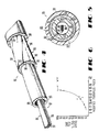
- FIG. 1 is a perspective view of a cable of this invention;
- FIG. 2 is an end cross-sectional view of the cable of FIG. 1;
- FIG. 3 is an enlarged view of a portion of interlocking shell segments in another embodiment of this invention;
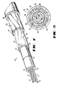
- FIG. 4 is a perspective view of an alternate embodiment of a cable of this invention;
- FIG. 5 is an end cross-sectional view of the cable of FIG. 4;
- FIG. 6 is a graph which depicts percent of cables surviving in a cage test versus a parameter referred to as modified toughness index;
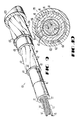
- FIG. 7 and 8 are perspective and end cross-sectional views of still another embodiment of this invention in which inner and outer shells enclose a cable core; and
- FIGS. 9 and 10 are perspective and end cross-sectional views of an alternate embodiment of the cable of FIGS. 7 and 8.
- Referring now to FIGS. 1 and 2, there is shown a cable which is designated generally by the numeral 20 and which is a cable having an all-
dielectric sheath system 21. The structure is such that it provides excellent protection against rodent attacks and lightning. - As can be seen in FIGS. 1 and 2, the
cable 20 includes a core 22 which comprises at least one transmission media. For example, thecore 22 may comprise one or more units 24-24 each of which includes a plurality of optical fibers 26-26. Each of the units 24-24 is provided with a binder 28. The unit or units is disposed within atubular member 30 which is made of a plastic material such as polyethylene, for example. - An inner diameter of the
tubular member 30 is such as to control the ratio of the total cross-sectional area of the coated optical fibers within the core to the cross-sectional area defined by the inner surface of the wall of the tubular member. This allows the optical fiber unit or units sufficient movement during handing, installation and temperature cycling to avoid losses due to microbending. - Further, the tubular member, or core tube as it is often called, may be filled with a suitable water blocking material 32. Such a material may be one such as that disclosed and claimed in U.S. patent 4,701,016.
- About the core tube is disposed a dielectric armor which is in the form of a shell and which is designated generally by the numeral 40. The
shell 40 comprises a plurality of individual preformed segments 42-42. The segments 42-42 are such that they cooperate to provide a generallycircular shell 40 for the core tube. Accordingly, eachsegment 42 is arcuately shaped and is disposed about the core tube such that asurface 46 thereof having the larger radius of curvature is oriented toward the outside of the cable. Further, the segments are arranged so that longitudinally extending side edge surfaces 48-48 of each are contiguous to longitudinally extending side edge surfaces of adjacent segments. Eachshell segment 42 is preformed to cause the longitudinal side surface 48-48 thereof to extend along radial lines from a longitudinal axis of the cable when the shell segment is disposed about the core. In one embodiment, the segments 42-42 may be bound with a binder (not shown) which is wrapped helically about the shell, although this is not necessary to hold the segments together. It is within the scope of this invention to include shell segments 47-47 (see FIG. 3) which interlock along longitudinal edge surfaces 49-49 thereof and which have a tongue and groove configuration, for example. This helps to prevent ingress of moisture through the sheath system and into the core and helps to bring the shell segments into alignment during their assembly in a manufacturing process. - The
shell 40 must be such that it does not impair the flexibility of the cable. For a cable which has a non-metallic sheath system and which is plowed into the ground in a buried installation, the cable must be capable of experiencing a bend radius equal to or less than the product of ten and the outer diameter of the cable without damaging the cable. Suitable flexibility is accomplished in two ways, first by causing the segments to be wrapped helically about the tubular member. Of course, the lay may be varied depending on cable size and use. Also, suitable flexibility is achieved by controlling the number of segments 42-42 in theshell 40. - The
shell 40 may comprise any number of segments 42-42 as long as each covers less than one-half the periphery of the core. In a preferred embodiment, eight segments 42-42 are used. It has been found that the larger the number of segments, the more flexible is the cable. However, too many segments will impede the alignment of the segments during their assembly about the core to form theshell 30. Also, inasmuch as seams between the shell segments may be most susceptible to rodent penetration, an unnecessary increase in the number of segments may increase the vulnerability of the cable to rodent damage. - Each of the segments 42-42 is made of a dielectric material such as organic or inorganic fibers embedded in a solid dielectric matrix material. In a preferred embodiment, each segment comprises glass fibers embedded in a cured epoxy matrix. However, the material from which the segments are made may be any one of a number of materials which are available commercially. What is important is that such material has relatively high tensile strength, relatively high compressive strength, is non-metallic and is a material which upon contact with the mouths of rodents discourages further attack. Such other materials include, for example, KEVLAR® fiber material, S Glass, T Glass or carbon fiber material in an epoxy matrix.
- In the preferred embodiment, glass rods available commercially from the Air Logistics Corp. under the designation E-glass tape are used. Each
shell segment 42 comprises a substrate which includes as many as 4000 continuous unidirectional fiber glass filaments bonded together in an epoxy material matrix. This causes the substrate to become relatively stiff and is rendered capable of withstanding expected compressive as well as tensile stresses. Expected compressive stresses include those which are induced by thermal cycling, and initial shrinkage of the jacket material, for example. In the preferred embodiment, eachshell segment 42 is characterized by a tensile stiffness of about 131 kg per one percent strain. - The radial thickness of each segment also is important. If too thick, the flexibility of the cable may be affected adversely. If too thin, the segments may break down under stresses imparted to the cable. It has been found that thicknesses in the range of about 0.51 - 1.02 mm are acceptable, depending, of course, on the cable size.
- For a
cable 20 which includes three units 24-24 each including twelve coated optical fibers having an outer diameter of 250 µm, the inner diameter of thecore tube 30 may be about 0.63 cm and the outer diameter about 0.78 cm. Eight shell segments each having a thickness of about 0.90 mm are used to provide an enclosingshell 40. The shell segments are stranded helically each with a lay of about 30 cm. - It also is important that the
cable 20 include provisions for preventing the ingress of water to the core. In the embodiment of FIGS. 1 and 2, water entry into the core is prevented by disposing a waterblockable tape 60 between theshell 40 and thetubular member 30. - The water
blockable tape 60 may comprise a laminate which includes a swellable superabsorbent powder disposed between two layers of cellulosic tissues. Preferably, thetape 60 is made of a hydrophobic material which has been treated with a water blockable material. Advantageously, the treated tape is hydrophilic. A hydrophilic material is one that has a strong affinity for water in that is absorbs water easily. - Preferably, the
tape 60 is a spunbonded, non-woven polyester material and includes a web structure comprised of randomly-arranged fibers which are bonded primarily at the filament crossovers. Continuity of the fibers of the web will provide the web with an increased tensile strength. The fibers may be formed of any plastic resin, or other appropriate material, which is substantially nonhygroscopic, and which has the capability of maintaining its shape in the presence of the temperatures encountered during extrusion of a portion of thecable 20. The fibers of the web structure are arranged so that air cells or pockets are formed. - A polyethylene terephthalate fiber product, formed into a web structure as described above, has been identified under the registered trademark "Reemay" by the E. I. du Pont de Nemours and Company, Incorporated of Wilmington, Del. Presently, the Reemay® web structure is available in various thicknesses and densities from Reemay, Inc. of Old Hickory, Tennessee. The properties of Reemay® tapes are further defined and described in Bulletin R-1, dated March, 1986, entitled "Properties and Processing of Reemay® Spunbonded Polyester" from E. I. du Pont de Nemours and Company, Incorporated, Wilmington, Delaware.
- Although in a preferred embodiment, a spunbonded polyester tape is used, others also are acceptable. For example, the tape which is to be impregnated may be a nylon spunbonded fabric, non-woven glass, polypropylene melt blown non-woven fabric, polyurethane spunbonded fabric or TCF cellulose fabric, for example.
- Another important characteristic of the
tape 60 is the stiffness of the body of the material which comprises the tape. Within limits, as the material of thetape 60 is made increasingly stiffer, it is still relatively easy to form the tape longitudinally about thecore tube 30, without wrinkling. However, it is important that the material be supple and flacid enough to conform readily to the contour of the outer surface of the core tube so that a minimal peripheral dimension is presented over which the shell segments 42-42 are applied. As a desirable consequence, a minimum overall diameter is achieved for the cable which will meet all the necessary requirements. - Stiffness of the material for the
tape 60 is controlled by a combination of factors such as the number of fibers per unit volume, thickness of the material, size of the fibers and the amount and type of binder used in the material. Increasing the thickness of the material obviously increases the cost of the material per unit of surface area of cable covered. Increasing the number of the fibers per unit volume or increasing the amount of binder tends to decrease the ability of the material to prevent heat transfer. Thus, at least four factors, formability of thetape 60, cost of the tape, insulative capability of the tape, and its water blocking capability must be considered and balanced in providing the proper material for use on a particular cable. - In a preferred embodiment, the
spunbonded polyester tape 60 combines the thermal, chemical and mechanical properties of polyester fibers with a spunbonded structure to provide a tape which is suitable for use in a communications cable. These properties include a relatively high tensile strength and elongation, excellent tear strength, and resistance to temperatures as high as about 254°C. - In order to render the substrate tape swellable upon contact with moisture, the
carrier tape 60 is impregnated with a suitable water swellable material which herein is referred to as a superabsorbent material. Superabsorbents are hydrophilic materials which can absorb and retain water under pressure without dissolution in the fluid being absorbed. See J. C. Djock and R. E. Klern "Review of Synthetic and Starch-Graft Copolymer Superabsorbents" prepared for the Absorbent Products Conference held November 16-17, 1983 in San Antonio, Texas and incorporated by reference hereinto. Properties such as enzyme stability, biodegradability, absorbent capacity and rate of uptake are used to characterize a superabsorbent material. One of the early superabsorbents was a saponified starch graft polyacrylonitrile copolymer. See U.S. patent 3,425,971. The above- identified patent discloses saponifying starch-graft polyacrylonitrile copolymers with aqueous bases. - The two major superabsorbents which are available today are cellulosic or starch-graft copolymers and synthetic superabsorbents. There are two major broad classes of synthetic superabsorbents. These are the polyelectrolytes and the nonelectrolytes. The polyelectrolytes are the most important and fall into four classes - polyacrylic acid superabsorbents, polymaleic anhydride-vinyl monomer superabsorbents, polyacrylonitrile-based superabsorbents and polyvinyl alcohol superabsorbents. Of these, the polyacrylic acid and polyacrylonitrile-based superabsorbents are most common. As with cellulosic-graft copolymer superabsorbents, the capacity of synthetic superabsorbents decreases with increasing salinity.
- The polyacrylic acid class of superabsorbents includes both homopolymers and copolymers of acrylic acids and acrylate esters. The monomer units usually are polymerized to produce a water-soluble polymer which is then rendered insoluble by ionic and/or covalent cross-linking. Cross-linking of the polymer may be accomplished with a multivalent cation, radiation, or with a cross-linking agent. The absorbency of the product is determined by the number of ionizable groups, usually carboxylates, and the cross-linking density.
- The cross-linking density affects not only the absorbency, but also the time required to absorb and the strength of the gel formed. Generally, the higher the cross-linking density, the stronger is the gel which is formed. The time to reach absorbent capacity decreases as the cross-linking density increases, and the absorbent capacity decreases.
- After the
substrate tape 60 has been impregnated, the superabsorbent material is dried to provide a film on the tape. It is desirable to impregnate thetape 60 with a film of the impregnating material instead of a powder. The impregnatedtape 60 may have a density of about 0.04 to 0.06 kg/m² which includes the density of the untreated tape increased 10 to 80%, i.e. the add-on, by the treating material. - The
spunbonded carrier tape 60 may be impregnated with any of several water blocking superabsorbent materials. It may be impregnated with a superabsorbent material which is derived from an aqueous solution comprising acrylate polymeric material which combines acrylic acid and sodium acrylate functionalities and water. - In another embodiment, a Reemay® spunbonded polyester tape is impregnated with an aqueous solution comprising acrylates and acrylamide polymer powders mixed with water. The tape impregnated with such a composition has a density which may represent an increase as high as about 80% of the density of the
untreated tape 60. - In general, the
tape 60 may be impregnated with (1) a material comprising polyacrylic acid, or (2) a material comprising polyacrylamide or (3) blends of (1) and (2) or salts thereof or (4) copolymers of acrylic acid and acrylamides and salts thereof or (5) copolymers of (1) and (2) which include styrene as well as other similar superabsorbents. In a preferred embodiment, the impregnating material is a mixture of water and a superabsorbent material in which the mixture comprises about 4 to 12 % solids when the impregnating material is an aqueous solution and applied. - Advantageously, in response to contact with water, the superabsorbent material in the
cable structure 20 swells to block the flow of water including that in a longitudinal direction. The superabsorbent material also forms a gel and changes the viscosity of the ingressed water at the point of contact with the superabsorbent material, making it more viscous and consequently developing more resistance to water flow. As a result, the flow of water longitudinally along a cable from a point of entry is reduced substantially. - The
tape 60 also possesses specific properties such as porosity and thickness which enhance its use as a water blocking element for a cable, particularly for a communications cable. Of importance is the need for the tape to be made of a material which has a relatively high porosity. It has been found that the water blockability of the tape increases as the porosity of the tape increases. Porosity may be measured by air permeability in units of cubic meters per square meter second at a specified water pressure. At 124 Pa of water pressure, typical porosities are in the range of about 0.7 to 5.1 m³/m²˙ s. - Evidently, because it is so porous and hence substantially cellular in structure, the
tape 60 is capable of accepting a substantial quantity of the impregnating material. As a result, entering water contacts a substantial area of the impregnating material which is water blocking. There is a surprisingly fast reaction between the water blocking material and the water causing the water blocking material to swell and block off further longitudinal movement of the water along the cable. - The porosity of the
untreated tape 60 decreases with increasing thickness. In a preferred embodiment, the Reemay® tape is style 2014 which at has a porosity of 4.1m³/m² ˙ s at 124 Pa. Reemay tape marketed under code designation 2014 has a density of 0.03 kg per square meter, has a thickness of 0.20 mm and is formed of substantially straight polyethylene terephthalate fibers. Various other grades of Reemay spunbonded polyester tape or other similar materials may be used. Material densities of up to about 0.07 kg per square meter are practical values. - Thickness of the
tape 60 also is important from another standpoint. In order to allow the cable to be terminated by standard size hardware, the diameter of the cable must be maintained within a desired range. Accordingly, the thickness of each element of the sheath system must be considered. Therefore, the thickness is established while being mindful of the porosity and the tensile strength. Thetape 60 must not be too thin, else the tensile strength is effected adversely, and if too thick, the porosity and overall cable outside diameter are affected adversely. Practical material thickness may range from about 0.13 mm to 0.30 mm thick. These values by no means limit the invention but represent the presently preferred ranges. - The sheath system of the
cable 20 also includes anouter jacket 65. Theouter jacket 65 may be made of a plastic material such as polyethylene and, for a cable which includes three units 24-24 of twelve optical fibers each, has an outer diameter of about 1.24 cm. - In the preferred embodiment, the
jacket 65 is decoupled from the shell segments. However, it is within the scope of this invention to cause the shell segments to be bonded to an inner surface of the outer jacket. For example, as seen in FIG. 3, an outer surface of eachsegment 47 is provided with acoating 67 of a suitable adhesive material which will cause thejacket 65 to bond to the shell. - Advantageously, the
shell 40 of this invention also acts as a thermal barrier. As the jacket is extruded over theshell 40, heat is available for transfer into the core. The segments 42-42 of thecable 20 insulate the core against the heat caused by the extrusion of the jacket. In fact, the shell segments obviate the need for a separate, well-known thermal core wrap about thecore tube 30. - In another embodiment which is shown in FIGS. 4 and 5, a
cable 80 includes a core 82 comprisingtransmission media 84 and a core tube 85. Thetransmission media 84 may be enclosed with acore wrap 83 disposed between the media and the core tube 85. Thecore wrap 83 protects themedia 84 during the extrusion of the core tube 85. In this embodiment, thetransmission media 84 may include a plurality of stacked ribbons 86-86. Eachribbon 86 includes a planar array of optical fibers 87-87. Enclosing the core tube 85 is ashell 88 comprising a plurality of arcuately shaped segments 90-90. In this embodiment, theshell 88 comprises four segments 90-90. - In the embodiment of FIGS. 4 and 5, each of the shell segments 90-90 is provided with a
coating 92 of a superabsorbent material. The superabsorbent material may be one which is used to impregnate thecarrier tape 60. Care must be taken to insure that longitudinal side edge surfaces 93 and 94 of each shell as well asmajor surfaces 96 and 98 are provided with the coating material. Such placement of the coating material and the arrangement of the shell segments with adjacent longitudinal edge surfaces being substantially contiguous will insure that the flow of water through the joints created between adjoining segments will be blocked. - Over the
shell 88 is disposed ajacket 99. As in the earlier described embodiment, thejacket 99 may be a plastic material such as polyethylene. - The above-described cable is a cable having an all-dielectric sheath system which is attractive from many standpoints. Being all-dielectric it certainly is suitable for use in lightning-prone areas as it would not attract lightning. Also it is non-corrosive and helps to avoid the problem of hydrogen generation in optical fiber cables.
- One of its most important features is its resistance to rodent attack. Being made of a material such as glass, it is not attractive to rodents as something to chew. The segments have great strength, are durable and discourage further attack by rodents after an initial encounter.
- One of several gauges of toughness of a sheath system is a parameter referred to as toughness index. It is found by multiplying ultimate tensile strength of the material by the strain at fracture. The toughness index which is expressed as the amount of energy absorbed per unit volume of material in Newtons · meters per cubic meter is modified to minimize effects of other parameters of the cable. Because the modified toughness index which is expressed in units of Newtons · meter per meter is a reliable indicator of the resistance to deformation wear caused by rodents, there is a correlation between increasing toughness and improving performance in cage tests. The cage test is well known and is described in the aforementioned paper by N.J. Cogelia, et al.
- The relationship between modified toughness index and percent surviving specimens is easily determined from the graph shown in FIG. 6. A correlation of improving performance with increasing toughness is readily apparent.
- In the Cogelia, et al. article, a table is provided to show a comparison of relative performance of one and two pair buried or distribution service wires with a helically applied shield. The modified toughness index and cage test percent surviving for a shield comprised of CPA 195 precipitation temper copper alloy were reported at 53 and 20 respectively whereas those parameters for a shield made of stainless steel type 304 annealed were 142 and 100. For an optical fiber cable of this invention having eight segments 0.76-0.89 mm thick with a breaking strength of 357 kg, the modified toughness index was 105 and the percent surviving the cage test was in the range of 90 to 100.
- As can be seen, the cable of this invention compares very favourably to one in which a stainless steel shield, is used. In view of the advantages of having an all-dielectric sheath system free of possible hydrogen generation but having inherent lightning protection, one can readily appreciate the value of the cable of this invention.
- The cables of this invention have been described as being rodent resistant. A rodent chewing into the glass fiber supported in an epoxy resin matrix will experience needle-like irritating glass fibers which penetrate the soft gum area of the mouth. This experience discourages subsequent attacks by the same rodent. It should be apparent that such cables are resistant not only to rodents but also to any animals such as sharks, for example, which have a propensity for attacking cables.
- In view of the foregoing, it should be readily apparent that the cable of this invention has excellent utility in the outdoor environment because of its outstanding protection against rodents and lightning. However, the cable of this invention also is adaptable to use indoors. Of course, use indoors demands that the cable be fire resistant. the segments which form the shell have excellent resistance to fire and smoke evolution. If the outer jacket is made of a fire-resistant material such as polyvinyl chloride, the cable also may be used indoors as a riser cable, for example.
- Referring now to FIGS. 7 and 8, there is shown another embodiment of this invention. A
cable 110 includes thecore 22 of FIG. 1 as well as theplastic core tube 30 and theshell 40. - In this embodiment, the
shell 40 is an inner shell and anouter shell 114 encloses the inner shell. Disposed over theouter shell 114 is aplastic jacket 116. - Each of the
shells segments cable 20 and the segments 90-90 of thecable 80. As such each has an arcuate cross sectional shape and each being made of a material comprising fibers held in a matrix material. Longitudinal edge surfaces of adjacent segments along radially lines abut each other. Further, the segments 42-42 of theinner shell 40 and the segments 120-120 of theouter shell 114 are wrapped helically about the cable core in opposite directions. Typically, the number of segments in theshell 114 is one greater than the number in theshell 40. Because two shell layers are used, the thickness of each shell segment, e.g. about 0.6 to 0.76 mm, may be less, than that of asegment 40 in thecable 20. - It has been found that the
cable 110 of FIG. 7 provides still greater resistance to animal attack than the cables of FIGS. 1 and 4. This is due to the double layer of rodent-resistant material and to the increased cable diameter. Also, theinner shell 40 provides more rigid support to very high compressive forces than does thecore tube 30 for the single shell of FIG. 1. - Further rodent resistance may be obtained with a
cable 130 of FIGS. 9 and 10. Therein, thecable 130 includes a core 22 enclosed in acore tube 30 with twoshells jacket 133. Theshell 40 comprises a plurality of longitudinally extending segments 42-42 and theshell 132 comprises a plurality of longitudinally extending segments 134-134. An innerplastic jacket 136 is disposed between the twoshells cable 20. - In preferred embodiments of the
cable 110 and thecable 130, the segments in theshells shells - It is to be understood that the above-described arrangements are simply illustrative of the invention. Other arrangements may be devised by those skilled in the art which will embody the principles of the invention and fall within the spirit and scope thereof.
Claims (10)
a plurality of longitudinally extending segments each of which has an arcuately shaped cross section transverse to a longitudinal axis of the cable and each of which is made of a dielectric material comprising fibers embedded in a matrix that discourages repeated attacks by the same animal and that provides suitable tensile and compressive strength for said cable, said segments cooperating to provide a shell enclosing said core with facing longitudinal edge surfaces of adjacent segments preformed to be substantially contiguous, and said segments being stranded helically about said core and being sufficient in number to allow said cable to be routed in a path having a predetermined radius without damaging said cable, said outer jacket being disposed about said segments.
Applications Claiming Priority (2)
| Application Number | Priority Date | Filing Date | Title |
|---|---|---|---|
| US194760 | 1988-05-17 | ||
| US07/194,760 US4874219A (en) | 1988-05-17 | 1988-05-17 | Animal-resistant cable |
Publications (3)
| Publication Number | Publication Date |
|---|---|
| EP0342855A2 true EP0342855A2 (en) | 1989-11-23 |
| EP0342855A3 EP0342855A3 (en) | 1991-05-22 |
| EP0342855B1 EP0342855B1 (en) | 1995-08-09 |
Family
ID=22718814
Family Applications (1)
| Application Number | Title | Priority Date | Filing Date |
|---|---|---|---|
| EP89304742A Expired - Lifetime EP0342855B1 (en) | 1988-05-17 | 1989-05-10 | Animal-resistant cable |
Country Status (9)
| Country | Link |
|---|---|
| US (1) | US4874219A (en) |
| EP (1) | EP0342855B1 (en) |
| JP (1) | JP2547253B2 (en) |
| KR (1) | KR0148354B1 (en) |
| CN (1) | CN1024376C (en) |
| CA (1) | CA1317139C (en) |
| DE (1) | DE68923733T2 (en) |
| DK (1) | DK236089A (en) |
| ES (1) | ES2075048T3 (en) |
Cited By (7)
| Publication number | Priority date | Publication date | Assignee | Title |
|---|---|---|---|---|
| EP0405851A1 (en) * | 1989-06-30 | 1991-01-02 | AT&T Corp. | Cable having non-metallic armoring layer |
| EP0412726A3 (en) * | 1989-08-11 | 1992-03-04 | American Telephone And Telegraph Company | Animal-resistant cable |
| US9201207B2 (en) | 2006-08-02 | 2015-12-01 | Schlumberger Technology Corporation | Packaging for encasing an optical fiber in a cable |
| US10062476B2 (en) | 2012-06-28 | 2018-08-28 | Schlumberger Technology Corporation | High power opto-electrical cable with multiple power and telemetry paths |
| US10087717B2 (en) | 2011-10-17 | 2018-10-02 | Schlumberger Technology Corporation | Dual use cable with fiber optics for use in wellbore operations |
| US10522271B2 (en) | 2016-06-09 | 2019-12-31 | Schlumberger Technology Corporation | Compression and stretch resistant components and cables for oilfield applications |
| US11725468B2 (en) | 2015-01-26 | 2023-08-15 | Schlumberger Technology Corporation | Electrically conductive fiber optic slickline for coiled tubing operations |
Families Citing this family (46)
| Publication number | Priority date | Publication date | Assignee | Title |
|---|---|---|---|---|
| US5138685A (en) * | 1990-01-23 | 1992-08-11 | At&T Bell Laboratories | Communications cable having microbial resistant water blocking provisions |
| US5188883A (en) * | 1990-03-22 | 1993-02-23 | Northern Telecom Limited | Composite tape structures |
| US5039197A (en) * | 1990-03-22 | 1991-08-13 | Northern Telecom Limited | Cable and tape structures therefor |
| US5179251A (en) * | 1990-06-27 | 1993-01-12 | At&T Bell Laboratories | Unshielded service wire for buried installation |
| US5003883A (en) * | 1990-07-23 | 1991-04-02 | The United States Of America As Represented By The Secretary Of The Army | Lightweight blast shield |
| US5131064A (en) * | 1991-02-19 | 1992-07-14 | At&T Bell Laboratories | Cable having lightning protective sheath system |
| TW215964B (en) * | 1992-05-29 | 1993-11-11 | American Telephone & Telegraph | Communication cable having water-blocking capabilities |
| US5305410A (en) * | 1993-02-02 | 1994-04-19 | At&T Bell Laboratories | Dielectric optical fiber cables which are magnetically locatable |
| US5305411A (en) * | 1993-02-26 | 1994-04-19 | At&T Bell Laboratories | Dielectric optical fiber cables which are magnetically locatable |
| US5384880A (en) * | 1993-12-03 | 1995-01-24 | Alcatel Na Cable Systems, Inc. | Dielectric ribbon optical fiber cable |
| US5577147A (en) * | 1994-03-31 | 1996-11-19 | Lucent Technologies Inc. | Magnetically locatable optical fiber cables containing integrated magnetic marker materials |
| US5426716A (en) * | 1994-03-31 | 1995-06-20 | At&T Corp. | Magnetically locatable non-metallic optical fiber cables |
| GB9411028D0 (en) * | 1994-06-02 | 1994-07-20 | Cookson Group Plc | Water blocking composites and their use in cable manufacture |
| US5567914A (en) * | 1994-09-30 | 1996-10-22 | Minnesota Mining And Manufacturing Company | Splice closure with animal protection |
| CA2161168C (en) * | 1994-12-20 | 2001-08-14 | John James Blee | Optical fiber cable for underwater use using terrestrial optical fiber cable |
| US5822484A (en) * | 1996-06-21 | 1998-10-13 | Lucent Technologies Inc. | Lightweight optical groundwire |
| US5997894A (en) * | 1997-09-19 | 1999-12-07 | Burlington Bio-Medical & Scientific Corp. | Animal resistant coating composition and method of forming same |
| US6238791B1 (en) | 1997-12-18 | 2001-05-29 | Ppg Industries Ohio, Inc. | Coated glass fibers, composites and methods related thereto |
| US6087000A (en) * | 1997-12-18 | 2000-07-11 | Ppg Industries Ohio, Inc. | Coated fiber strands, composites and cables including the same and related methods |
| DE10016536A1 (en) * | 2000-04-03 | 2001-10-04 | Roblon As Frederikshavn | Cable-reinforcing element, especially for optical cables, has a core containing filaments embedded in thermoplastic adhesive and an outer skin of thermoplastic adhesive containing a water-absorbent swelling agent |
| DE10035267B4 (en) * | 2000-07-20 | 2007-09-06 | CCS Technology, Inc., Wilmington | Optical cable and duct or pipe system with an installed optical cable |
| US20040050581A1 (en) * | 2002-09-18 | 2004-03-18 | Hager Thomas P. | Low cost, high performance flexible reinforcement for communications cable |
| US7435909B2 (en) * | 2002-09-18 | 2008-10-14 | Neptco Jv Llc | Low cost, high performance flexible reinforcement for communications cable |
| US20040050579A1 (en) * | 2002-09-18 | 2004-03-18 | Hager Thomas P. | Low cost, high performance flexible reinforcement for communications cable |
| US7421169B2 (en) * | 2003-06-20 | 2008-09-02 | Fujikura Ltd. | Optical fiber cable |
| US7287489B1 (en) | 2003-11-19 | 2007-10-30 | O'brien John P | Pet deterrent device |
| WO2011063221A2 (en) | 2009-11-20 | 2011-05-26 | Adc Telecommunications, Inc. | Fiber optic cable |
| JP2012220856A (en) * | 2011-04-13 | 2012-11-12 | Furukawa Electric Co Ltd:The | Cable |
| JP5830266B2 (en) * | 2011-04-13 | 2015-12-09 | 古河電気工業株式会社 | cable |
| JP5947558B2 (en) * | 2012-02-16 | 2016-07-06 | 株式会社フジクラ | Fiber optic cable |
| US20150007487A1 (en) * | 2013-07-03 | 2015-01-08 | Rockwell Automation Technologies, Inc. | System and method for incorporation of pest repellent with bus bar cover components |
| JP6310309B2 (en) * | 2014-04-16 | 2018-04-11 | 古河電気工業株式会社 | Ant measures power cable |
| CN104614829B (en) * | 2015-03-10 | 2017-12-05 | 浙江金冠特种变压器有限公司 | A kind of anti-unfirmly closing optical cable and preparation method thereof |
| CN104614827B (en) * | 2015-03-10 | 2018-01-16 | 深圳市奥威尔通信科技有限公司 | Anti- unfirmly closing optical cable, anti-unfirmly closing cable and preparation method thereof |
| CN107065108A (en) * | 2015-03-10 | 2017-08-18 | 沈群华 | Anti- unfirmly closing optical cable and preparation method thereof |
| CN104656216B (en) * | 2015-03-10 | 2017-11-28 | 胡磊盈 | Anti- unfirmly closing optical cable and its manufacture method |
| CN104614828B (en) * | 2015-03-10 | 2018-01-23 | 重庆成瑞光电科技有限公司 | A kind of anti-unfirmly closing optical cable and its manufacture method |
| GB2567101A (en) | 2016-09-22 | 2019-04-03 | Halliburton Energy Services Inc | Optical fiber cable protected from animal bite |
| CN109791817A (en) | 2016-09-29 | 2019-05-21 | 普睿司曼股份公司 | Cable with lightweight stretching element |
| US10354779B2 (en) * | 2017-03-31 | 2019-07-16 | Radix Wire & Cable, Llc | Free air fire alarm cable |
| WO2019108384A1 (en) | 2017-11-30 | 2019-06-06 | Corning Research & Development Corporation | Fiber optic cable for distributed sensing with rodent resistant components from hardened materials |
| CN108037573A (en) * | 2018-01-31 | 2018-05-15 | 成都亨通光通信有限公司 | Anti- bird, anti-rodent, anti-slungshot optical cable, the production technology and production mould of optical cable |
| FR3078815B1 (en) * | 2018-03-09 | 2022-02-25 | Tresse Ind | IRRITANT PROTECTIVE WRAP |
| MX2020014314A (en) | 2018-06-26 | 2021-03-09 | Corning Res & Dev Corp | High density bundled optical fiber cable with preconnectorized drop points. |
| CN111540514A (en) * | 2020-06-17 | 2020-08-14 | 重庆渝丰电线电缆有限公司 | Cable capable of reducing electromagnetic interference |
| CN112820458B (en) * | 2020-12-23 | 2021-12-10 | 喜天奇(江苏)电子有限公司 | Fire-proof rat-proof polyurethane sheath net wire |
Citations (2)
| Publication number | Priority date | Publication date | Assignee | Title |
|---|---|---|---|---|
| DE3502042A1 (en) * | 1985-01-23 | 1986-07-24 | Standard Elektrik Lorenz Ag, 7000 Stuttgart | Cable with rodent protection |
| EP0248221A2 (en) * | 1986-05-28 | 1987-12-09 | AT&T Corp. | Optical fiber cable having non-metallic sheath system |
Family Cites Families (13)
| Publication number | Priority date | Publication date | Assignee | Title |
|---|---|---|---|---|
| JPS5141171Y2 (en) * | 1971-05-06 | 1976-10-07 | ||
| US3878444A (en) * | 1974-01-21 | 1975-04-15 | Tesco Eng Co | Method and apparatus for protecting electrical field cables against rodent damage |
| DE2455273C3 (en) * | 1974-11-22 | 1978-01-19 | Feiten & Guilleaume Carlswerk AG, 5000 Köln | Plastic crane rope |
| US3973385A (en) * | 1975-05-05 | 1976-08-10 | Consolidated Products Corporation | Electromechanical cable |
| US4146302A (en) * | 1975-06-02 | 1979-03-27 | General Cable Corporation | Construction of cable made of optical fibres |
| US4171463A (en) * | 1978-02-17 | 1979-10-16 | David Watkins | Rodent proof cable |
| US4309072A (en) * | 1980-04-15 | 1982-01-05 | The United States Of America As Represented By The Secretary Of The Air Force | Cable protection from rodents |
| US4437789A (en) * | 1981-09-24 | 1984-03-20 | Gk Technologies, Incorporated | Method and means for protecting buried cable from rodent damage |
| US4505541A (en) * | 1982-03-31 | 1985-03-19 | Sea-Log Corporation | Rodent-resistant non-conductive optical fiber cable |
| US4557560A (en) * | 1983-11-15 | 1985-12-10 | At&T Technologies, Inc. | Rodent and lightning protective sheath system for cables |
| DE3568233D1 (en) * | 1984-02-10 | 1989-03-16 | Cables De Lyon Geoffroy Delore | Electrical cable to transport very high current strengths under low tensions, and manufacturing methods for such a cable |
| US4652861A (en) * | 1985-06-04 | 1987-03-24 | Gte Sprint Communications Corporation | Method and apparatus for protecting buried optical fiber cable |
| US4770489A (en) * | 1986-08-27 | 1988-09-13 | Sumitomo Electric Research Triangle, Inc. | Ruggedized optical communication cable |
-
1988
- 1988-05-17 US US07/194,760 patent/US4874219A/en not_active Expired - Lifetime
-
1989
- 1989-05-10 ES ES89304742T patent/ES2075048T3/en not_active Expired - Lifetime
- 1989-05-10 DE DE68923733T patent/DE68923733T2/en not_active Expired - Fee Related
- 1989-05-10 EP EP89304742A patent/EP0342855B1/en not_active Expired - Lifetime
- 1989-05-12 JP JP1117628A patent/JP2547253B2/en not_active Expired - Fee Related
- 1989-05-15 KR KR1019890006456A patent/KR0148354B1/en not_active IP Right Cessation
- 1989-05-16 CN CN89104433A patent/CN1024376C/en not_active Expired - Fee Related
- 1989-05-16 CA CA000599802A patent/CA1317139C/en not_active Expired - Fee Related
- 1989-05-16 DK DK236089A patent/DK236089A/en not_active Application Discontinuation
Patent Citations (2)
| Publication number | Priority date | Publication date | Assignee | Title |
|---|---|---|---|---|
| DE3502042A1 (en) * | 1985-01-23 | 1986-07-24 | Standard Elektrik Lorenz Ag, 7000 Stuttgart | Cable with rodent protection |
| EP0248221A2 (en) * | 1986-05-28 | 1987-12-09 | AT&T Corp. | Optical fiber cable having non-metallic sheath system |
Cited By (9)
| Publication number | Priority date | Publication date | Assignee | Title |
|---|---|---|---|---|
| EP0405851A1 (en) * | 1989-06-30 | 1991-01-02 | AT&T Corp. | Cable having non-metallic armoring layer |
| EP0412726A3 (en) * | 1989-08-11 | 1992-03-04 | American Telephone And Telegraph Company | Animal-resistant cable |
| US9201207B2 (en) | 2006-08-02 | 2015-12-01 | Schlumberger Technology Corporation | Packaging for encasing an optical fiber in a cable |
| US10087717B2 (en) | 2011-10-17 | 2018-10-02 | Schlumberger Technology Corporation | Dual use cable with fiber optics for use in wellbore operations |
| US10062476B2 (en) | 2012-06-28 | 2018-08-28 | Schlumberger Technology Corporation | High power opto-electrical cable with multiple power and telemetry paths |
| US11725468B2 (en) | 2015-01-26 | 2023-08-15 | Schlumberger Technology Corporation | Electrically conductive fiber optic slickline for coiled tubing operations |
| US10522271B2 (en) | 2016-06-09 | 2019-12-31 | Schlumberger Technology Corporation | Compression and stretch resistant components and cables for oilfield applications |
| US11335478B2 (en) | 2016-06-09 | 2022-05-17 | Schlumberger Technology Corporation | Compression and stretch resistant components and cables for oilfield applications |
| US11776712B2 (en) | 2016-06-09 | 2023-10-03 | Schlumberger Technology Corporation | Compression and stretch resistant components and cables for oilfield applications |
Also Published As
| Publication number | Publication date |
|---|---|
| KR0148354B1 (en) | 1998-11-16 |
| KR890017724A (en) | 1989-12-18 |
| JPH01320707A (en) | 1989-12-26 |
| EP0342855A3 (en) | 1991-05-22 |
| DK236089D0 (en) | 1989-05-16 |
| DE68923733D1 (en) | 1995-09-14 |
| ES2075048T3 (en) | 1995-10-01 |
| EP0342855B1 (en) | 1995-08-09 |
| JP2547253B2 (en) | 1996-10-23 |
| DE68923733T2 (en) | 1996-01-18 |
| CN1038704A (en) | 1990-01-10 |
| CA1317139C (en) | 1993-05-04 |
| US4874219A (en) | 1989-10-17 |
| CN1024376C (en) | 1994-04-27 |
| DK236089A (en) | 1989-11-18 |
Similar Documents
| Publication | Publication Date | Title |
|---|---|---|
| EP0342855B1 (en) | Animal-resistant cable | |
| US4946237A (en) | Cable having non-metallic armoring layer | |
| US4938560A (en) | Animal-resistant cable | |
| US5131064A (en) | Cable having lightning protective sheath system | |
| JP2726714B2 (en) | communication cable | |
| EP0314371B1 (en) | Water resistant communications cable | |
| US4913517A (en) | Communication cable having water blocking strength members | |
| CA2096567C (en) | Communication cable having water-blocking capabilities | |
| EP0314991B1 (en) | Water resistant communications cable | |
| CA2098212C (en) | Optical fiber cable which includes waterblocking and freeze preventing provisions | |
| US20050265673A1 (en) | Buffer tubes with improved flexibility | |
| CA2061775A1 (en) | Cable having waterblocking provisions between layers of relatively rigid and supple materials | |
| AU660861B2 (en) | Optical fiber cable which includes waterblocking and freeze preventing provisions |
Legal Events
| Date | Code | Title | Description |
|---|---|---|---|
| PUAI | Public reference made under article 153(3) epc to a published international application that has entered the european phase |
Free format text: ORIGINAL CODE: 0009012 |
|
| AK | Designated contracting states |
Kind code of ref document: A2 Designated state(s): BE CH DE ES FR GB IT LI NL SE |
|
| PUAL | Search report despatched |
Free format text: ORIGINAL CODE: 0009013 |
|
| AK | Designated contracting states |
Kind code of ref document: A3 Designated state(s): BE CH DE ES FR GB IT LI NL SE |
|
| 17P | Request for examination filed |
Effective date: 19911030 |
|
| 17Q | First examination report despatched |
Effective date: 19930308 |
|
| RAP3 | Party data changed (applicant data changed or rights of an application transferred) |
Owner name: AT&T CORP. |
|
| GRAA | (expected) grant |
Free format text: ORIGINAL CODE: 0009210 |
|
| AK | Designated contracting states |
Kind code of ref document: B1 Designated state(s): BE CH DE ES FR GB IT LI NL SE |
|
| ITF | It: translation for a ep patent filed |
Owner name: JACOBACCI & PERANI S.P.A. |
|
| ET | Fr: translation filed | ||
| REF | Corresponds to: |
Ref document number: 68923733 Country of ref document: DE Date of ref document: 19950914 |
|
| REG | Reference to a national code |
Ref country code: ES Ref legal event code: FG2A Ref document number: 2075048 Country of ref document: ES Kind code of ref document: T3 |
|
| REG | Reference to a national code |
Ref country code: CH Ref legal event code: NV Representative=s name: BOVARD AG PATENTANWAELTE |
|
| PLBE | No opposition filed within time limit |
Free format text: ORIGINAL CODE: 0009261 |
|
| STAA | Information on the status of an ep patent application or granted ep patent |
Free format text: STATUS: NO OPPOSITION FILED WITHIN TIME LIMIT |
|
| 26N | No opposition filed | ||
| PGFP | Annual fee paid to national office [announced via postgrant information from national office to epo] |
Ref country code: SE Payment date: 20010321 Year of fee payment: 13 |
|
| PGFP | Annual fee paid to national office [announced via postgrant information from national office to epo] |
Ref country code: CH Payment date: 20010323 Year of fee payment: 13 |
|
| PGFP | Annual fee paid to national office [announced via postgrant information from national office to epo] |
Ref country code: BE Payment date: 20010427 Year of fee payment: 13 |
|
| PGFP | Annual fee paid to national office [announced via postgrant information from national office to epo] |
Ref country code: ES Payment date: 20010504 Year of fee payment: 13 |
|
| PGFP | Annual fee paid to national office [announced via postgrant information from national office to epo] |
Ref country code: DE Payment date: 20010629 Year of fee payment: 13 |
|
| REG | Reference to a national code |
Ref country code: GB Ref legal event code: IF02 |
|
| PGFP | Annual fee paid to national office [announced via postgrant information from national office to epo] |
Ref country code: FR Payment date: 20020417 Year of fee payment: 14 |
|
| PGFP | Annual fee paid to national office [announced via postgrant information from national office to epo] |
Ref country code: GB Payment date: 20020501 Year of fee payment: 14 |
|
| PG25 | Lapsed in a contracting state [announced via postgrant information from national office to epo] |
Ref country code: SE Free format text: LAPSE BECAUSE OF NON-PAYMENT OF DUE FEES Effective date: 20020511 Ref country code: ES Free format text: LAPSE BECAUSE OF NON-PAYMENT OF DUE FEES Effective date: 20020511 |
|
| PG25 | Lapsed in a contracting state [announced via postgrant information from national office to epo] |
Ref country code: LI Free format text: LAPSE BECAUSE OF NON-PAYMENT OF DUE FEES Effective date: 20020531 Ref country code: CH Free format text: LAPSE BECAUSE OF NON-PAYMENT OF DUE FEES Effective date: 20020531 Ref country code: BE Free format text: LAPSE BECAUSE OF NON-PAYMENT OF DUE FEES Effective date: 20020531 |
|
| PGFP | Annual fee paid to national office [announced via postgrant information from national office to epo] |
Ref country code: NL Payment date: 20020703 Year of fee payment: 14 |
|
| PG25 | Lapsed in a contracting state [announced via postgrant information from national office to epo] |
Ref country code: DE Free format text: LAPSE BECAUSE OF NON-PAYMENT OF DUE FEES Effective date: 20021203 |
|
| EUG | Se: european patent has lapsed | ||
| REG | Reference to a national code |
Ref country code: CH Ref legal event code: PL |
|
| PG25 | Lapsed in a contracting state [announced via postgrant information from national office to epo] |
Ref country code: GB Free format text: LAPSE BECAUSE OF NON-PAYMENT OF DUE FEES Effective date: 20030510 |
|
| PG25 | Lapsed in a contracting state [announced via postgrant information from national office to epo] |
Ref country code: NL Free format text: LAPSE BECAUSE OF NON-PAYMENT OF DUE FEES Effective date: 20031201 |
|
| GBPC | Gb: european patent ceased through non-payment of renewal fee |
Effective date: 20030510 |
|
| PG25 | Lapsed in a contracting state [announced via postgrant information from national office to epo] |
Ref country code: FR Free format text: LAPSE BECAUSE OF NON-PAYMENT OF DUE FEES Effective date: 20040130 |
|
| NLV4 | Nl: lapsed or anulled due to non-payment of the annual fee |
Effective date: 20031201 |
|
| REG | Reference to a national code |
Ref country code: FR Ref legal event code: ST |
|
| REG | Reference to a national code |
Ref country code: ES Ref legal event code: FD2A Effective date: 20030611 |
|
| PG25 | Lapsed in a contracting state [announced via postgrant information from national office to epo] |
Ref country code: IT Free format text: LAPSE BECAUSE OF NON-PAYMENT OF DUE FEES;WARNING: LAPSES OF ITALIAN PATENTS WITH EFFECTIVE DATE BEFORE 2007 MAY HAVE OCCURRED AT ANY TIME BEFORE 2007. THE CORRECT EFFECTIVE DATE MAY BE DIFFERENT FROM THE ONE RECORDED. Effective date: 20050510 |