EP0248221A2 - Optical fiber cable having non-metallic sheath system - Google Patents
Optical fiber cable having non-metallic sheath system Download PDFInfo
- Publication number
- EP0248221A2 EP0248221A2 EP87106490A EP87106490A EP0248221A2 EP 0248221 A2 EP0248221 A2 EP 0248221A2 EP 87106490 A EP87106490 A EP 87106490A EP 87106490 A EP87106490 A EP 87106490A EP 0248221 A2 EP0248221 A2 EP 0248221A2
- Authority
- EP
- European Patent Office
- Prior art keywords
- strength members
- cable
- jacket
- optical fiber
- strength
- Prior art date
- Legal status (The legal status is an assumption and is not a legal conclusion. Google has not performed a legal analysis and makes no representation as to the accuracy of the status listed.)
- Granted
Links
- 239000013307 optical fiber Substances 0.000 title claims abstract description 31
- 239000004033 plastic Substances 0.000 claims abstract description 19
- 229920003023 plastic Polymers 0.000 claims abstract description 19
- 239000002131 composite material Substances 0.000 claims abstract description 8
- 230000008602 contraction Effects 0.000 claims abstract description 6
- 239000000463 material Substances 0.000 claims description 17
- 239000011521 glass Substances 0.000 claims description 13
- 239000003365 glass fiber Substances 0.000 claims description 13
- 239000000835 fiber Substances 0.000 claims description 5
- 239000004593 Epoxy Substances 0.000 claims description 3
- 229920002635 polyurethane Polymers 0.000 claims description 3
- 239000004814 polyurethane Substances 0.000 claims description 3
- 239000003989 dielectric material Substances 0.000 claims 4
- 239000010410 layer Substances 0.000 description 48
- 230000008878 coupling Effects 0.000 description 9
- 238000010168 coupling process Methods 0.000 description 9
- 238000005859 coupling reaction Methods 0.000 description 9
- 238000005452 bending Methods 0.000 description 6
- 238000004519 manufacturing process Methods 0.000 description 5
- 239000000758 substrate Substances 0.000 description 5
- 238000005538 encapsulation Methods 0.000 description 3
- 238000005382 thermal cycling Methods 0.000 description 3
- 238000005299 abrasion Methods 0.000 description 2
- 230000005540 biological transmission Effects 0.000 description 2
- 230000015556 catabolic process Effects 0.000 description 2
- 238000005253 cladding Methods 0.000 description 2
- 238000006731 degradation reaction Methods 0.000 description 2
- 239000002356 single layer Substances 0.000 description 2
- 229910000831 Steel Inorganic materials 0.000 description 1
- 238000005229 chemical vapour deposition Methods 0.000 description 1
- 239000011248 coating agent Substances 0.000 description 1
- 238000000576 coating method Methods 0.000 description 1
- 230000006835 compression Effects 0.000 description 1
- 238000007906 compression Methods 0.000 description 1
- 230000007423 decrease Effects 0.000 description 1
- 238000009826 distribution Methods 0.000 description 1
- 230000000694 effects Effects 0.000 description 1
- 230000001747 exhibiting effect Effects 0.000 description 1
- 239000003000 extruded plastic Substances 0.000 description 1
- 239000011152 fibreglass Substances 0.000 description 1
- 229920001903 high density polyethylene Polymers 0.000 description 1
- 239000004700 high-density polyethylene Substances 0.000 description 1
- 238000009434 installation Methods 0.000 description 1
- 210000003127 knee Anatomy 0.000 description 1
- 239000011159 matrix material Substances 0.000 description 1
- 238000000034 method Methods 0.000 description 1
- 239000000203 mixture Substances 0.000 description 1
- 230000003287 optical effect Effects 0.000 description 1
- 239000004800 polyvinyl chloride Substances 0.000 description 1
- 230000003014 reinforcing effect Effects 0.000 description 1
- 239000012260 resinous material Substances 0.000 description 1
- 238000004513 sizing Methods 0.000 description 1
- 239000010959 steel Substances 0.000 description 1
- 230000002459 sustained effect Effects 0.000 description 1
Images


Classifications
-
- G—PHYSICS
- G02—OPTICS
- G02B—OPTICAL ELEMENTS, SYSTEMS OR APPARATUS
- G02B6/00—Light guides; Structural details of arrangements comprising light guides and other optical elements, e.g. couplings
- G02B6/44—Mechanical structures for providing tensile strength and external protection for fibres, e.g. optical transmission cables
- G02B6/4401—Optical cables
- G02B6/4429—Means specially adapted for strengthening or protecting the cables
- G02B6/443—Protective covering
- G02B6/4431—Protective covering with provision in the protective covering, e.g. weak line, for gaining access to one or more fibres, e.g. for branching or tapping
-
- G—PHYSICS
- G02—OPTICS
- G02B—OPTICAL ELEMENTS, SYSTEMS OR APPARATUS
- G02B6/00—Light guides; Structural details of arrangements comprising light guides and other optical elements, e.g. couplings
- G02B6/44—Mechanical structures for providing tensile strength and external protection for fibres, e.g. optical transmission cables
- G02B6/4401—Optical cables
- G02B6/4429—Means specially adapted for strengthening or protecting the cables
- G02B6/44384—Means specially adapted for strengthening or protecting the cables the means comprising water blocking or hydrophobic materials
Definitions
- This invention relates to an optical fiber cable having a non-metallic sheath system in which non-metallic strength members are disposed in two contiguous layers about a core with some of the strength members being capable of withstanding expected compressive as well as tensile forces.
- optical fibers Although desired for their large bandwidth capabilities and small size, light-transmitting optical fibers are mechanically fragile, exhibiting low-strain fracture under tensile loading and degraded light transmission when bent. The degradation in transmission which results from bending is known as microbending loss.
- cable structures have been developed to protect mechanically the optical fibers in various environments. For example, a cable for use in a duct must be capable of withstanding tensile loads applied when the cable is pulled into the duct and stresses caused by bends.
- Cable structures which have been developed for optical fibers include a cable disclosed in U. S. patent 4,241,979 which issued on December 30, 1980 in the names of P. F. Gagen and M. R. Santana.
- a beading layer, about which strength members are wrapped helically, is added between plastic extruded inner and outer jackets to control the extent to which the strength members are encapsulated by the outer jacket.
- the cable includes two separate layers of metallic strength members, which are wrapped helically in opposite directions. Under a sustained tensile load, these two layers of strength members produce equal but oppositely directed torques about the cable to insure the absence of twisting.
- the strength members not only provide the necessary strength characteristics for the cable, but also reinforce the sheath and help protect the optical fiber from external influences.
- the metallic wires of the cable in the hereinbefore-identified Gagen-Santana patent have been replaced with glass fiber, rod-like members.
- the rod-like members are capable of withstanding expected ccmpressive as well as tensile loading. Compressive loading occurs when the cable tends to contract during initial shrinkage of the jacket material and during thermal cycling.
- Compressive loading occurs when the cable tends to contract during initial shrinkage of the jacket material and during thermal cycling.
- the use of a sufficient number of glass rods to provide the cable with suitable load carrying capability causes the cable to be relatively stiff.
- the inner plastic jacket which separates the two layers of oppositely wound rods adds additional steps to the manufacture of the cable.
- the sought-after cable should be adaptable to a variety of environments and accommodate a plurality of optical fibers in a totally dielectric structure. Also, the sought-after cable should be one Which is more flexible than those now available commercially and one which does not compromise established strength requirements.
- the optical fiber cable includes a core comprising one or more optical fibers which may be stranded or one or more optical fiber ribbons and a tubular plastic member Which encloses the core.
- the core and the tubular member are enclosed in a non-metallic sheath system which includes a plastic jacket.
- Interposed between the tubular member and the jacket is a layer of strength members.
- a first plurality of the strength members are relatively flexible and a second plurality of the strength members have sufficient compressive stiffness and are coupled sufficiently to the jacket to provide a composite arrangement which is effective to inhibit contraction of the cable.
- the first and second pluralities of strength members cooperate to provide the cable with a desired load carrying capability at a strain which does not exceed a predetermined value.
- the strength members are disposed in two layers with an inner layer engaging the tubular member and the outer layer engaging the inner layer.
- Strength members which are capable of resisting expected buckling forces are disposed in the outermost layer whereas strength members which are relatively flexible and which primarily resist tension are disposed in at least the innermost layer.
- the strength members which are capable of resisting buckling are rod-like and comprised of glass fiber filaments whereas the other strength members are relatively flexible and also are comprised of glass filaments.
- Prior art cables have included two layers of glass rod-like strength members separated by a plastic jacket.
- the cable of this invention provides necesssary strength requirements by the cooperation between a plurality of rod-like glass fiber members and a plurality of relatively flexible glass fiber members. Further, the cables of this invention do not include an inner plastic jacket between the layers of the strength members.
- the optical fiber cable includes a core 22 which comprises one or more optical fibers 23-23.
- Each optical fiber includes a core and a cladding and a coating which encloses the cladding.
- the optical fibers 23-23 may be mads by the modified chemical vapor deposition process, for example, as disclosed in U. S. patent 4,217,027 which issued on August 12, 1980 in the names of J. B. MacChesney and P. O'Connor.
- the core 22 is enclosed in a tubular member 28 which extends longitudinally along the cable.
- the tubular member 28 which is sometimes referred to as a core tube is made of a plastic material such as high density polyethylene or polyvinyl chloride (PVC).
- a suitable waterblocking material 29 may be used to fill the interstices among the optical fibers and between the fibers and the tubular member 28.
- the non-metallic sheath system 30 includes a strength member system 32 and an outer plastic jacket 36.
- the strength member system 32 must meet several criteria. First, it must have sufficient strength in compression to resist stresses induced by thermal cycling as well as bending and in tension to resist stresses induced by bending and by pulling. At least portions of the strength member system must be coupled sufficiently to the jacket so that the portions of the strength member system and the jacket provide a composite arrangement which resists buckling. Further, the cable must be relatively flexible. Also, the cross-sectional shape of the portions of the strength member system must not be overly large.
- the strength member system 32 includes an inner first layer 40 of relatively flexible strength members 42-42 which are in engagement with the tubular member 28.
- Each of the strength members 42-42 comprises a glass fiber member such as a glass roving or yarn marketed by PPG Industries, for example, which is impregnated with a resinous material, for example.
- each of the strength members 42-42 is a glass roving and is wrapped helically about the tubular member 28.
- Each roving is characterized by a load carrying capability in tension of about 88 lbs. per one percent strain. The load per unit strain is defined as stiffness.
- each of the majority of the strength members of the outer layer is designated 52 and comprises a relatively inflexible rod-like member which is made of glass fibers in the form of a yarn or roving. Such glass rods are available commercially from the Air Logistics Corp. under the designation E-glass tape.
- the outer layer 50 also includes several of the strength members 42-42.
- the strength members 52-52 and 42-42 of the outer layer are wrapped helically about the strength members of the inner layer but in an opposite helical direction from those of the inner layer.
- the strength member system includes two layers of helically wrapped strength members, other arrangements come within the invention.
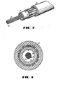
- the strength members of the cable 20 may be assembled to the cable without intended stranding (see FIG. 3).
- the strength members may be disposed in a single layer (see FIGS. 3 and 4). This is particularly true in a ribbon core cable in which the outer diameter of the tubular member 28 is larger than for the cables of FIGS. 1 and 2, thereby allowing a greater number of strength members to be disposed about its circumference.
- each of the rod-like members 52-52 and the relatively flexible strength members 42-42 of the preferred embodiment comprises a substrate which is made of E-glass fiber filaments.
- Each substrate may comprise as many as 4000 fiber glass filaments.
- the substrate is impregnated with an epoxy material. This causes the substrate to become relatively stiff and is rendered capable of withstanding expected compressive as well as tensile stresses. Expected compressive stresses include those which are induced by thermal cycling, and initial shrinkage of the jacket material, for example.
- each strength member 52 is characterized by a tensile stiffness of about 347 Newtons (N) which equates to 78 lbs in the English system per one percent strain.
- the glass fiber substrate is a roving and must be treated further to maintain suitable strength properties.
- the sizing is not sufficient to prevent abrasion among the fibers when they slide relative to one another during tensile loading of the cable 20.
- it is impregnated with a polyurethane matrix material. Unlike the epoxy material, the polyurethane material does not cause the roving to become relatively inflexible. Instead, it preserves the flexibility and tensile strength of the glass roving while preventing abrasion among the fibers when slippage therebetween occurs.
- the strength members 42-42 are sufficiently flexible and are sufficient in number to cause the cable 20 to be relatively flexible.
- Torque balancing of the cable of FIGS. 1 and 2 is made easier because the absence of an inner jacket between the layers of the strength members allows the use of the same lay length for the strength members of both layers. Further, a lay length which is longer than that of some prior art cables may be used. This allows the use of higher line speeds during manufacture of the cable.
- the strength member system In order for the cable to have suitable strength characteristics, the strength member system must be coupled to the jacket 36. It should be understood that the plastic of the outer jacket encapsulates portions of the strength members and couples thereto. If the coupling of the strength members to the jacket is excessive, bending of the cable could result in buckling of the strength members with respect to the jacket 36. Therefore, provisions must be made for controlling the coupling of the strength members to the jacket 36.
- a bedding layer shields portions of the strength members from the extrudate of the enclosing jacket.
- the core 22 and tubular member 28 are surrounded by an inner jacket 61 and an intermediate jacket 63 each of which jackets is made of a plastic material.
- partially embedded in each jacket 61 and 63 are a plurality of longitudinally extending strength members 64-64 which may be steel wires or glass rods..
- Portions of the strength members are in intimate contact with bedding layers 65-65 to render predetermined surfaces of the strength members sufficiently inaccessible for coupling with the plastic extrudate which is used to provide the overlying jacket. This reduces jacket-strength member coupling so that the strength members can more readily slide with respect to the jacket plastic during local cable bending.
- the prior art cable of FIGS. 5 and 6 may also be provided with an oversheath shield system 67 which underlies an outer jacket 68.
- the shield system 67 may include an inner metallic shield 69 and an outer metallic shield 71 which is bonded to the jacket 68 to enhance moisture protection and to enhance the mechanical performance of the cable.
- This cable is disclosed and claimed in U. S. Patent 4,557,560 which issued on December 10, 1985 in the names of W. D. Bohannon, Jr. et al.
- FIGS. 1 and 2 also is effective to control any coupling between the strength members and the jacket 36. Portions of the strength members are sufficiently inaccessible for coupling with the plastic jacket 36. Portions of the strength members of the inner layer which engage the core tube 28 and the portions of the strength members of each layer which engage each other are not embedded in plastic material and hence are decoupled from the jacket. This prevents complete encapsulation of the strength members. As a result of this arrangement, a slippage plane is provided for the plurality of longitudinally extending strength members which are disposed along the tubular member 28.
- the strength members are caused to be disposed about the tubular member 28 under tension so that portions of the surfaces of the strength members make intimate surface contact with the tubular member and with each other. Then, the jacket 36 is pressure-extruded over the strength members.
- the contact between the inner layer 40 of strength members and the core tube and between the inner and outer layers of strength members is such as to inhibit the flow of the jacket plastic extrudate to the portions of the surfaces so that encapsulation of those surfaces is prevented. This reduces jacket-strength member coupling sufficiently so that the strength members can more readily slide with respect to the jacket during local cable bending.
- the jacket 36 When the extruded plastic material of the jacket 36 cools during manufacture, it forms a tight fit about at least some of the strength members. During tensile loading of the cables, the helically wrapped strength members attempt to move radially but are prevented from doing so by the underlying tubular member 28.
- the jacket For the strength members which engage the tubular member in a single layer system or for those of the outer layer which engage the inner layer, the jacket forms generally a split-type ring. This arrangement substantially mitigates against relative circumferential movement of the strength members with respect to the jacket, and more easily allows relative movement of the strength members in a longitudinal direction with respect to the jacket under local herding.
- Contraction of the cable may occur during initial Shrinkage of the plastic jacket material and during exposure to temperatures which may be as low as -40°C (-40°F) . If only the relatively flexible strength members 42-42 were contiguous to the jacket: 36, the composite arrangement of them and the jackert may not be effective to withstand expected buckling forces ,
- the cables of this invention provide excellent optical performance with substantially no added losses at temperatures at least as low as -40°C (-40°F) .
- the cable of this invention is such that it can withstand a 2670 N (600 lbs.) load at a strain which does not exceed 0.33%.
- FIG. 7 there is shown a graph 80 of load versus strain.
- a curve 82 reflects the relationship of load and strain for one prior art cable discussed hereinbefore.
- one prior art cable includes two layers of strength members with . the layers being separated by an inner jacket and with all the strength members being relatively stiff glass rods. Because the cable 20 of this invention includes a plurality of relatively flexible glass fiber members in the inner layer in a somewhat undulated configuration longitudinally of the cable, portions of a tensile load are not immediately taken up by than but only after they are taut.
- a curve 90 which depicts the relationship of load and strain for the cable of this invention includes a portion 92 Which has a slope that is less than that of the curve 80 for the prior art cable.
- the remainder of the curve 90 that is a portion 94, has a slope greater than that of the portion 92 and greater than that of the curve 80 of the prior art cable.
- the force-strain curves characteristic of the cables of this invantion need not include a knee as shown in FIG. 7.
- the relative numbers of the two kinds of strength members may be optimized to provide the cable with sufficient strength characteristics as well as flexibility.
- the number of relatively stiff strength members 52-52 may be increased sufficiently to cause the force-strain curve to be similar to the curve 82 which is unbroken.
- such a cable would include a plurality of strength members 42-42, although not as many as shown in FIGS. 1 and 2, to impart flexibility to the cable.
- inner and outer diameters of the core tube are 4.3 mm (0.17 inch) and 6.1 mn (0.24 inch), respectively, whereas inner and outer diameters of the outer jacket are 8.13 mm (0.32 inch) and 10.7 mn (0.42 inch), respectively.
- the inner layer 40 includes twelve rovings 42-42 and the outer layer 50 includes two rovings 42-42 and ten glass rod-like members 52-52 with all of the members being equally spaced about the cable periphery. Also, in the preferred embodiment, the two rovings 42-42 in the outer layer are diametrically opposite to each other.
- the advantages of the cable 20 of this invention should be apparent.
- the inner jacket of plastic material of prior art cables has been removed.
- a hybrid mix of relatively flexible and relatively stiff, rod-like glass fiber members instead of glass rods exclusively has been used to provide the tensile stiffness which is required for the cable and to cause the resulting cable to be more flexible than its predecessor.
- the monolithic strength member system of the prior art has been replaced with a hybrid system of this invention, the strength system is such that it is capable of a predetermined load carrying capacity at a strain which is less than a predetermined value.
- the cable 20 of this invention is characterized by several additional advantages over cables of the prior art. For example, it is more flexible and has a smaller outer diameter than the so-called cross-ply cable of U. S. patent 4,241,979. Also, as can be seen from FIGS. 5 and 6, because the layers of strength members of the prior art cable depicted therein are ssparated by an inner jacket, a longer lay length is required for each of the helically wound strength members in the outer layer than for each strength member of the inner layer in order to manufacture a torsionally balanced cable. With the cable of this invention, the strength member layers are contiguous to each other which allows the use of a lay length which is the same for both layers and which is longer than that of the inner layer of prior art cables. In the preferred embodiment the lay length of each strength member is about 31,75 cm (12.5 inches).
- the cable 20 of this invention has a non-metallic sheath system whereas in the cable of FIGS. 5 and 6, metallic strength members are used and a metallic shield system underlies the outer jacket.
- the cables of FIGS. 1, 2, and 3 do not require metallic grounding arrangements across splices and in closures. Further, the inventive cable is much less apt to be victimized by lightning strikes.
Landscapes
- Physics & Mathematics (AREA)
- General Physics & Mathematics (AREA)
- Optics & Photonics (AREA)
- Insulated Conductors (AREA)
- Communication Cables (AREA)
- Laminated Bodies (AREA)
- Light Guides In General And Applications Therefor (AREA)
Abstract
Description
- This invention relates to an optical fiber cable having a non-metallic sheath system in which non-metallic strength members are disposed in two contiguous layers about a core with some of the strength members being capable of withstanding expected compressive as well as tensile forces.
- Although desired for their large bandwidth capabilities and small size, light-transmitting optical fibers are mechanically fragile, exhibiting low-strain fracture under tensile loading and degraded light transmission when bent. The degradation in transmission which results from bending is known as microbending loss. As a result, cable structures have been developed to protect mechanically the optical fibers in various environments. For example, a cable for use in a duct must be capable of withstanding tensile loads applied when the cable is pulled into the duct and stresses caused by bends.
- Cable structures which have been developed for optical fibers include a cable disclosed in U. S. patent 4,241,979 which issued on December 30, 1980 in the names of P. F. Gagen and M. R. Santana. A beading layer, about which strength members are wrapped helically, is added between plastic extruded inner and outer jackets to control the extent to which the strength members are encapsulated by the outer jacket. The cable includes two separate layers of metallic strength members, which are wrapped helically in opposite directions. Under a sustained tensile load, these two layers of strength members produce equal but oppositely directed torques about the cable to insure the absence of twisting. Advantageously, the strength members not only provide the necessary strength characteristics for the cable, but also reinforce the sheath and help protect the optical fiber from external influences.
- Although the cable of U.S. patent 4,241,979 meets the aforementioned needs, efforts have continued to find alternatives. Further, what is desired is a totally dielectric cable. Such a cable which could be run from building ducts to service distribution points would obviate the need for grounding connections at splice points that add to the cost of the cable installations. Also, such a cable decreases substantially the probability of lightning strikes.
- In the prior art, to achieve a totally dielectric structure, the metallic wires of the cable in the hereinbefore-identified Gagen-Santana patent have been replaced with glass fiber, rod-like members. The rod-like members are capable of withstanding expected ccmpressive as well as tensile loading. Compressive loading occurs when the cable tends to contract during initial shrinkage of the jacket material and during thermal cycling. However, the use of a sufficient number of glass rods to provide the cable with suitable load carrying capability causes the cable to be relatively stiff. Also, the inner plastic jacket which separates the two layers of oppositely wound rods adds additional steps to the manufacture of the cable.
- What is needed and what seemingly is not provided by the prior art is a cable having a compact and relatively flexible non-metallic sheath system which is capable of withstanding conpressive as well as tensile loading. The sought-after cable should be adaptable to a variety of environments and accommodate a plurality of optical fibers in a totally dielectric structure. Also, the sought-after cable should be one Which is more flexible than those now available commercially and one which does not compromise established strength requirements.
- The foregoing problems of the prior art have been overcome by an optical fiber cable of this invention. The optical fiber cable includes a core comprising one or more optical fibers which may be stranded or one or more optical fiber ribbons and a tubular plastic member Which encloses the core. The core and the tubular member are enclosed in a non-metallic sheath system which includes a plastic jacket. Interposed between the tubular member and the jacket is a layer of strength members. A first plurality of the strength members are relatively flexible and a second plurality of the strength members have sufficient compressive stiffness and are coupled sufficiently to the jacket to provide a composite arrangement which is effective to inhibit contraction of the cable. The first and second pluralities of strength members cooperate to provide the cable with a desired load carrying capability at a strain which does not exceed a predetermined value.
- In a preferred embodiment, the strength members are disposed in two layers with an inner layer engaging the tubular member and the outer layer engaging the inner layer. Strength members which are capable of resisting expected buckling forces are disposed in the outermost layer whereas strength members which are relatively flexible and which primarily resist tension are disposed in at least the innermost layer. Preferably, the strength members which are capable of resisting buckling are rod-like and comprised of glass fiber filaments whereas the other strength members are relatively flexible and also are comprised of glass filaments.
- Prior art cables have included two layers of glass rod-like strength members separated by a plastic jacket. Advantageously, the cable of this invention provides necesssary strength requirements by the cooperation between a plurality of rod-like glass fiber members and a plurality of relatively flexible glass fiber members. Further, the cables of this invention do not include an inner plastic jacket between the layers of the strength members.
-
- FIG. 1 is a perspective view of an optical fiber cable of this invention;
- FIG. 2 is an end view of the cable of FIG. 1;
- FIG. 3 is a perspective view of another cable of this invention;
- FIG. 4 is an end view of the cable of FIG. 3;
- FIG. 5 is a perspective view of a prior art optical fiber cable;
- FIG. 6 is an end view of the prior art optical fiber cable of FIG. 5 ; and
- FIG. 7 is a graph which shows curves of force plotted against strain for a prior art cable and for one embodiment of a cable of this invention.
- Referring now to FIGS. 1 and 2, there is shown an
optical fiber cable 20 of this invention. The optical fiber cable includes acore 22 which comprises one or more optical fibers 23-23. Each optical fiber includes a core and a cladding and a coating which encloses the cladding. The optical fibers 23-23 may be mads by the modified chemical vapor deposition process, for example, as disclosed in U. S. patent 4,217,027 which issued on August 12, 1980 in the names of J. B. MacChesney and P. O'Connor. - The
core 22 is enclosed in a tubular member 28 which extends longitudinally along the cable. The tubular member 28 which is sometimes referred to as a core tube is made of a plastic material such as high density polyethylene or polyvinyl chloride (PVC). A suitable waterblocking material 29 may be used to fill the interstices among the optical fibers and between the fibers and the tubular member 28. - Enclosing the
core 22 and the tubular member 28 is a non-metallic sheath system which is designated generally by thenumeral 30. Thenon-metallic sheath system 30 includes astrength member system 32 and an outerplastic jacket 36. - The
strength member system 32 must meet several criteria. First, it must have sufficient strength in compression to resist stresses induced by thermal cycling as well as bending and in tension to resist stresses induced by bending and by pulling. At least portions of the strength member system must be coupled sufficiently to the jacket so that the portions of the strength member system and the jacket provide a composite arrangement which resists buckling. Further, the cable must be relatively flexible. Also, the cross-sectional shape of the portions of the strength member system must not be overly large. - The
strength member system 32 includes an innerfirst layer 40 of relatively flexible strength members 42-42 which are in engagement with the tubular member 28. Each of the strength members 42-42 comprises a glass fiber member such as a glass roving or yarn marketed by PPG Industries, for example, which is impregnated with a resinous material, for example. In a preferred embodiment, each of the strength members 42-42 is a glass roving and is wrapped helically about the tubular member 28. Each roving is characterized by a load carrying capability in tension of about 88 lbs. per one percent strain. The load per unit strain is defined as stiffness. - Another component of the
strength member system 32 is an outer second layer 50 of strength members which are in engagement with the strength members 42-42 of theinner layer 40. As can be seen in the drawings, each of the majority of the strength members of the outer layer is designated 52 and comprises a relatively inflexible rod-like member which is made of glass fibers in the form of a yarn or roving. Such glass rods are available commercially from the Air Logistics Corp. under the designation E-glass tape. In the embodiment shown in FIG. 1, the outer layer 50 also includes several of the strength members 42-42. For the preferred embodiment, the strength members 52-52 and 42-42 of the outer layer are wrapped helically about the strength members of the inner layer but in an opposite helical direction from those of the inner layer. - Although in the preferred embodiment, the strength member system includes two layers of helically wrapped strength members, other arrangements come within the invention. For example, the strength members of the
cable 20 may be assembled to the cable without intended stranding (see FIG. 3). - Also the strength members may be disposed in a single layer (see FIGS. 3 and 4). This is particularly true in a ribbon core cable in which the outer diameter of the tubular member 28 is larger than for the cables of FIGS. 1 and 2, thereby allowing a greater number of strength members to be disposed about its circumference.
- It should be noted that each of the rod-like members 52-52 and the relatively flexible strength members 42-42 of the preferred embodiment comprises a substrate which is made of E-glass fiber filaments. Each substrate may comprise as many as 4000 fiber glass filaments. For the strength members 52-52 of the preferred embodiment, the substrate is impregnated with an epoxy material. This causes the substrate to become relatively stiff and is rendered capable of withstanding expected compressive as well as tensile stresses. Expected compressive stresses include those which are induced by thermal cycling, and initial shrinkage of the jacket material, for example. In the preferred embodiment, each
strength member 52 is characterized by a tensile stiffness of about 347 Newtons (N) which equates to 78 lbs in the English system per one percent strain. - For the strength members of the
inner layer 40 and for several of the strength members of the outer layer of the preferred embodiment, the glass fiber substrate is a roving and must be treated further to maintain suitable strength properties. Although the glass fibers are sized, the sizing is not sufficient to prevent abrasion among the fibers when they slide relative to one another during tensile loading of thecable 20. Accordingly, in order to prevent a degradation of the tensile strength properties of the roving, it is impregnated with a polyurethane matrix material. Unlike the epoxy material, the polyurethane material does not cause the roving to become relatively inflexible. Instead, it preserves the flexibility and tensile strength of the glass roving while preventing abrasion among the fibers when slippage therebetween occurs. The strength members 42-42 are sufficiently flexible and are sufficient in number to cause thecable 20 to be relatively flexible. - Torque balancing of the cable of FIGS. 1 and 2 is made easier because the absence of an inner jacket between the layers of the strength members allows the use of the same lay length for the strength members of both layers. Further, a lay length which is longer than that of some prior art cables may be used. This allows the use of higher line speeds during manufacture of the cable.
- In order for the cable to have suitable strength characteristics, the strength member system must be coupled to the
jacket 36. It should be understood that the plastic of the outer jacket encapsulates portions of the strength members and couples thereto. If the coupling of the strength members to the jacket is excessive, bending of the cable could result in buckling of the strength members with respect to thejacket 36. Therefore, provisions must be made for controlling the coupling of the strength members to thejacket 36. - In earlier mentioned U. S. patent 4, 241, 979, a bedding layer shields portions of the strength members from the extrudate of the enclosing jacket. As shown in FIGS. 5 and 6, the
core 22 and tubular member 28 are surrounded by an inner jacket 61 and anintermediate jacket 63 each of which jackets is made of a plastic material. Further, partially embedded in eachjacket 61 and 63 are a plurality of longitudinally extending strength members 64-64 which may be steel wires or glass rods.. Portions of the strength members are in intimate contact with bedding layers 65-65 to render predetermined surfaces of the strength members sufficiently inaccessible for coupling with the plastic extrudate which is used to provide the overlying jacket. This reduces jacket-strength member coupling so that the strength members can more readily slide with respect to the jacket plastic during local cable bending. - The prior art cable of FIGS. 5 and 6 may also be provided with an
oversheath shield system 67 which underlies an outer jacket 68. Theshield system 67 may include an innermetallic shield 69 and an outermetallic shield 71 which is bonded to the jacket 68 to enhance moisture protection and to enhance the mechanical performance of the cable. This cable is disclosed and claimed in U. S. Patent 4,557,560 which issued on December 10, 1985 in the names of W. D. Bohannon, Jr. et al. - The arrangement of FIGS. 1 and 2 also is effective to control any coupling between the strength members and the
jacket 36. Portions of the strength members are sufficiently inaccessible for coupling with theplastic jacket 36. Portions of the strength members of the inner layer which engage the core tube 28 and the portions of the strength members of each layer which engage each other are not embedded in plastic material and hence are decoupled from the jacket. This prevents complete encapsulation of the strength members. As a result of this arrangement, a slippage plane is provided for the plurality of longitudinally extending strength members which are disposed along the tubular member 28. - During manufacture, the strength members are caused to be disposed about the tubular member 28 under tension so that portions of the surfaces of the strength members make intimate surface contact with the tubular member and with each other. Then, the
jacket 36 is pressure-extruded over the strength members. The contact between theinner layer 40 of strength members and the core tube and between the inner and outer layers of strength members is such as to inhibit the flow of the jacket plastic extrudate to the portions of the surfaces so that encapsulation of those surfaces is prevented. This reduces jacket-strength member coupling sufficiently so that the strength members can more readily slide with respect to the jacket during local cable bending. - Preventing encapsulation of these surfaces has little effect on the reinforcing tensile strength of the strength members. When the extruded plastic material of the
jacket 36 cools during manufacture, it forms a tight fit about at least some of the strength members. During tensile loading of the cables, the helically wrapped strength members attempt to move radially but are prevented from doing so by the underlying tubular member 28. For the strength members which engage the tubular member in a single layer system or for those of the outer layer which engage the inner layer, the jacket forms generally a split-type ring. This arrangement substantially mitigates against relative circumferential movement of the strength members with respect to the jacket, and more easily allows relative movement of the strength members in a longitudinal direction with respect to the jacket under local herding. - Sufficient coupling exists between strength members of the cable of this invention and the
jacket 36 to ensure composite structural behavior between those strangth members and the jacket in a longitudinal direction over the complete length of the cable, Such coupling is established with the strength members immediately adjacent to thejacket 36. Therefore, in order to provide the cable of the preferred embodiment with suitable campressive strength, it is important that the relatively inflexible strength members 52-52 are disposed in the outer layer 50 and contiguous to thejacket 36. This arrangement allows the strength members 52-52 to become coupled sufficiently to thejacket 36. so that those strength members and the jacket provide a composite arrangement which is effective to inhibit contraction of the cable. Contraction of the cable may occur during initial Shrinkage of the plastic jacket material and during exposure to temperatures which may be as low as -40°C (-40°F) , If only the relatively flexible strength members 42-42 were contiguous to the jacket: 36, the composite arrangement of them and the jackert may not be effective to withstand expected buckling forces , The cables of this invention provide excellent optical performance with substantially no added losses at temperatures at least as low as -40°C (-40°F) . - The cable of this invention is such that it can withstand a 2670 N (600 lbs.) load at a strain which does not exceed 0.33%. Viewing now FIG. 7, there is shown a graph 80 of load versus strain. In that graph, a
curve 82 reflects the relationship of load and strain for one prior art cable discussed hereinbefore. As will be recalled, that one prior art cable includes two layers of strength members with . the layers being separated by an inner jacket and with all the strength members being relatively stiff glass rods. Because thecable 20 of this invention includes a plurality of relatively flexible glass fiber members in the inner layer in a somewhat undulated configuration longitudinally of the cable, portions of a tensile load are not immediately taken up by than but only after they are taut. As-a result, acurve 90 which depicts the relationship of load and strain for the cable of this invention includes a portion 92 Which has a slope that is less than that of the curve 80 for the prior art cable. In order to prevent the strain at a 2670 N (600 Ibs.) loading from exceeding 0.33%, the remainder of thecurve 90, that is a portion 94, has a slope greater than that of the portion 92 and greater than that of the curve 80 of the prior art cable. - It should be noted that the force-strain curves characteristic of the cables of this invantion need not include a knee as shown in FIG. 7. The relative numbers of the two kinds of strength members may be optimized to provide the cable with sufficient strength characteristics as well as flexibility. For example, the number of relatively stiff strength members 52-52 may be increased sufficiently to cause the force-strain curve to be similar to the
curve 82 which is unbroken. Of course, such a cable would include a plurality of strength members 42-42, although not as many as shown in FIGS. 1 and 2, to impart flexibility to the cable. - In the preferred embodiment of this invention, inner and outer diameters of the core tube are 4.3 mm (0.17 inch) and 6.1 mn (0.24 inch), respectively, whereas inner and outer diameters of the outer jacket are 8.13 mm (0.32 inch) and 10.7 mn (0.42 inch), respectively. The
inner layer 40 includes twelve rovings 42-42 and the outer layer 50 includes two rovings 42-42 and ten glass rod-like members 52-52 with all of the members being equally spaced about the cable periphery. Also, in the preferred embodiment, the two rovings 42-42 in the outer layer are diametrically opposite to each other. - The advantages of the
cable 20 of this invention should be apparent. For example, the inner jacket of plastic material of prior art cables has been removed. Also, a hybrid mix of relatively flexible and relatively stiff, rod-like glass fiber members instead of glass rods exclusively, has been used to provide the tensile stiffness which is required for the cable and to cause the resulting cable to be more flexible than its predecessor. Although the monolithic strength member system of the prior art has been replaced with a hybrid system of this invention, the strength system is such that it is capable of a predetermined load carrying capacity at a strain which is less than a predetermined value. - The
cable 20 of this invention is characterized by several additional advantages over cables of the prior art. For example, it is more flexible and has a smaller outer diameter than the so-called cross-ply cable of U. S. patent 4,241,979. Also, as can be seen from FIGS. 5 and 6, because the layers of strength members of the prior art cable depicted therein are ssparated by an inner jacket, a longer lay length is required for each of the helically wound strength members in the outer layer than for each strength member of the inner layer in order to manufacture a torsionally balanced cable. With the cable of this invention, the strength member layers are contiguous to each other which allows the use of a lay length which is the same for both layers and which is longer than that of the inner layer of prior art cables. In the preferred embodiment the lay length of each strength member is about 31,75 cm (12.5 inches). - Also, the
cable 20 of this invention has a non-metallic sheath system whereas in the cable of FIGS. 5 and 6, metallic strength members are used and a metallic shield system underlies the outer jacket. As a result, the cables of FIGS. 1, 2, and 3 do not require metallic grounding arrangements across splices and in closures. Further, the inventive cable is much less apt to be victimized by lightning strikes. - It should be understood that the above-described arrangements are simply illustrative of the invention. Other arrangements may be devised by those skilled in the art which will embody the principles of the invention and fall within the scope and spirit thereof.
Claims (10)
CHARACTERIZED IN THAT
Applications Claiming Priority (2)
| Application Number | Priority Date | Filing Date | Title |
|---|---|---|---|
| US867643 | 1978-01-06 | ||
| US06/867,643 US4743085A (en) | 1986-05-28 | 1986-05-28 | Optical fiber cable having non-metallic sheath system |
Publications (3)
| Publication Number | Publication Date |
|---|---|
| EP0248221A2 true EP0248221A2 (en) | 1987-12-09 |
| EP0248221A3 EP0248221A3 (en) | 1989-05-10 |
| EP0248221B1 EP0248221B1 (en) | 1995-04-05 |
Family
ID=25350184
Family Applications (1)
| Application Number | Title | Priority Date | Filing Date |
|---|---|---|---|
| EP87106490A Expired - Lifetime EP0248221B1 (en) | 1986-05-28 | 1987-05-05 | Optical fiber cable having non-metallic sheath system |
Country Status (9)
| Country | Link |
|---|---|
| US (1) | US4743085A (en) |
| EP (1) | EP0248221B1 (en) |
| JP (1) | JP2523129B2 (en) |
| KR (1) | KR960013801B1 (en) |
| CN (1) | CN1012221B (en) |
| CA (1) | CA1294165C (en) |
| DE (1) | DE3751213T2 (en) |
| DK (1) | DK271887A (en) |
| ES (1) | ES2070114T3 (en) |
Cited By (4)
| Publication number | Priority date | Publication date | Assignee | Title |
|---|---|---|---|---|
| EP0284900A3 (en) * | 1987-03-31 | 1990-05-30 | American Telephone And Telegraph Company | Optical fiber building cables |
| EP0342855A3 (en) * | 1988-05-17 | 1991-05-22 | AT&T Corp. | Animal-resistant cable |
| AU622004B2 (en) * | 1989-04-06 | 1992-03-26 | American Telephone And Telegraph Company | Underwater optical fiber cable |
| DE19740726B4 (en) * | 1996-09-16 | 2006-02-09 | Samsung Electronics Co., Ltd., Suwon | Overhead line optical fiber cable |
Families Citing this family (47)
| Publication number | Priority date | Publication date | Assignee | Title |
|---|---|---|---|---|
| GB8704217D0 (en) * | 1987-02-24 | 1987-04-01 | British Telecomunications Plc | Cables |
| US4850672A (en) * | 1988-02-19 | 1989-07-25 | Siecor Corporation | Strain compensated fiber optic cable |
| US5071221A (en) * | 1988-08-05 | 1991-12-10 | Mitsubishi Petrochemical Company Limited | Water penetration preventive cable |
| US4892382A (en) * | 1988-09-26 | 1990-01-09 | Siecor Corporation | Dielectric optical drop cable |
| DE3837285A1 (en) * | 1988-11-03 | 1990-05-10 | Rheydt Kabelwerk Ag | Low-torsion optical cable |
| US5109457A (en) * | 1988-12-14 | 1992-04-28 | At&T Bell Laboratories | All-dielectric optical fiber cable having enhanced fiber access |
| US4946237A (en) * | 1989-06-30 | 1990-08-07 | At&T Bell Laboratories | Cable having non-metallic armoring layer |
| US5029974A (en) * | 1990-01-22 | 1991-07-09 | Alcatel Na Cable Systems, Inc. | Unitube optical fiber cable |
| US5013127A (en) * | 1990-04-26 | 1991-05-07 | Siecor Corporation | Flexible fiber optic distribution cable |
| US5050957A (en) * | 1990-04-27 | 1991-09-24 | At&T Bell Laboratories | Optical fiber service cable |
| US5119457A (en) * | 1990-08-15 | 1992-06-02 | University Research Engineers & Associates, Inc. | High-performance electric power cable and connector system |
| US5101467A (en) * | 1990-11-23 | 1992-03-31 | Siecor Corporation | Cable having embedded optical fiber |
| US5249249A (en) * | 1991-08-27 | 1993-09-28 | Siecor Corporation | Cable utilizing multiple light waveguide stacks |
| US5740295A (en) * | 1994-11-02 | 1998-04-14 | Lucent Technologies Inc. | Low fiber count optical cable |
| US5561729A (en) * | 1995-05-15 | 1996-10-01 | Siecor Corporation | Communications cable including fiber reinforced plastic materials |
| DE19605276A1 (en) | 1996-02-13 | 1997-08-14 | Siemens Ag | Method and device for manufacturing an optical cable |
| KR100452496B1 (en) * | 1996-04-29 | 2004-12-30 | 엔케이 케이블스 오와이 | Multi-layer reinforced and stabilized cable construction |
| US5838864A (en) * | 1997-04-30 | 1998-11-17 | Lucent Technologies Inc. | Optical cable having an improved strength system |
| US6167180A (en) * | 1997-09-12 | 2000-12-26 | Alcatel | Cable having at least one layer of flexible strength members with adhesive and non-adhesive yarns for coupling an outer protective jacket and a buffer tube containing optical fibers |
| US6178278B1 (en) * | 1997-11-13 | 2001-01-23 | Alcatel | Indoor/outdoor dry optical fiber cable |
| EP1916554A1 (en) | 1997-11-13 | 2008-04-30 | Nexans | Indoor/outdoor dry optical fiber cable |
| US6041153A (en) * | 1998-07-01 | 2000-03-21 | Alcatel | Continuous composite reinforced buffer tubes for optical fiber cables |
| US6253012B1 (en) | 1998-11-12 | 2001-06-26 | Alcatel | Cycled fiber lock for cross-functional totally dry optical fiber loose tube cable |
| US6198865B1 (en) | 1999-08-13 | 2001-03-06 | Alcatel | Telecommunications cable having good adhesion between a protective jacket and strength members |
| US6611646B1 (en) | 1999-10-08 | 2003-08-26 | Fitel Usa Corp. | Hybrid strength member for an optical cable |
| US6778744B2 (en) | 1999-10-08 | 2004-08-17 | Fitel Usa Corp. | Dielectric optical fiber cable having reduced preferential bending |
| DE20210216U1 (en) * | 2002-02-09 | 2003-03-20 | CCS Technology, Inc., Wilmington, Del. | Optical fiber cable, comprises outer cover and additionally incorporates concentric inner cover which surrounds bundles of optical fibers, takes up tensile loads and functions as support |
| KR100442605B1 (en) * | 2002-03-04 | 2004-08-02 | 삼성전자주식회사 | Lightweight optical cable |
| US6847768B2 (en) * | 2002-09-06 | 2005-01-25 | Corning Cable Systems Llc | Optical fiber tube assembly having a plug |
| KR100526506B1 (en) * | 2003-05-27 | 2005-11-08 | 삼성전자주식회사 | Optical cable for air blow installation |
| US6813422B1 (en) | 2003-06-23 | 2004-11-02 | Alcoa Fujikura Limited | Flexible fiber optic cable |
| DE102005002186A1 (en) * | 2005-01-17 | 2006-07-27 | CCS Technology, Inc., Wilmington | Optical cable, assembly for connecting a plurality of optical waveguides and method for producing an optical cable |
| US7902989B2 (en) * | 2007-05-31 | 2011-03-08 | Cox Raleigh L | Optical switch |
| US7702203B1 (en) | 2008-10-30 | 2010-04-20 | Corning Cable Systems Llc | Armored fiber optic assemblies and methods of making the same |
| JP2010128169A (en) * | 2008-11-27 | 2010-06-10 | Furukawa Electric Co Ltd:The | Optical fiber cable |
| US8463095B2 (en) * | 2009-04-09 | 2013-06-11 | Corning Cable Systems Llc | Armored fiber optic assemblies and methods of forming fiber optic assemblies |
| US20100278492A1 (en) | 2009-04-30 | 2010-11-04 | Bohler Gregory B | Armored Fiber Optic Assemblies and Methods of Forming Fiber Optic Assemblies |
| US8331748B2 (en) * | 2009-09-30 | 2012-12-11 | Corning Cable Systems Llc | Armored fiber optic assemblies and methods employing bend-resistant multimode fiber |
| US9170390B2 (en) | 2010-04-23 | 2015-10-27 | Corning Cable Systems Llc | Armored fiber optic assemblies and methods of forming fiber optic assemblies |
| MX337524B (en) * | 2010-06-08 | 2016-03-09 | Dow Global Technologies Llc | THERMOPLASTIC RESISTANCE ELEMENT REINFORCED BY FIBER, PARTIALLY IMPROGATED. |
| CN105549168A (en) * | 2016-01-29 | 2016-05-04 | 烽火通信科技股份有限公司 | Military field operation optical cables and manufacture method thereof |
| CN106125220A (en) * | 2016-07-18 | 2016-11-16 | 江苏中天科技股份有限公司 | A kind of anti-animal of nonmetal lightweight bites optical cable |
| CN209167604U (en) * | 2018-06-27 | 2019-07-26 | 罗森伯格技术(昆山)有限公司 | A kind of outdoor armored optical cable |
| CN110908056A (en) * | 2019-12-28 | 2020-03-24 | 江苏亨通光电股份有限公司 | High-low temperature resistant remote optical cable and manufacturing process thereof |
| CN112497788B (en) * | 2020-11-11 | 2022-11-22 | 振石集团华智研究院(浙江)有限公司 | Carbon glass composite FRP optical cable reinforced core and production method thereof |
| US12276852B2 (en) * | 2021-03-30 | 2025-04-15 | Sterlite Technologies Limited | Rewindable optical fiber cable |
| US20220373759A1 (en) * | 2021-05-24 | 2022-11-24 | Ofs Fitel, Llc | Optical cable with high aspect ratio strength rods |
Family Cites Families (15)
| Publication number | Priority date | Publication date | Assignee | Title |
|---|---|---|---|---|
| US4146302A (en) * | 1975-06-02 | 1979-03-27 | General Cable Corporation | Construction of cable made of optical fibres |
| US4330173A (en) * | 1976-03-22 | 1982-05-18 | Siemens Aktiengesellschaft | Conductor for optical cables |
| US4331378A (en) * | 1976-10-22 | 1982-05-25 | E. I. Du Pont De Nemours And Company | Reinforced optical fiber cable with glass or silica core |
| JPS541643A (en) * | 1977-06-06 | 1979-01-08 | Nippon Telegr & Teleph Corp <Ntt> | Submarine fiber cable |
| IT1092793B (en) * | 1978-02-24 | 1985-07-12 | Pirelli | PERFECTED SUBMARINE CABLE |
| US4169657A (en) * | 1978-03-02 | 1979-10-02 | Akzona Incorporated | Laminated strength members for fiber optic cable |
| US4241979A (en) * | 1979-01-18 | 1980-12-30 | Bell Telephone Laboratories, Incorporated | Optical communication cable with means for controlling coupling between cable jacket and strength members |
| US4374608A (en) * | 1979-02-05 | 1983-02-22 | Belden Corporation | Fiber optic cable |
| US4342500A (en) * | 1979-08-10 | 1982-08-03 | Siemens Aktiengesellschaft | High voltage stabile optical cable structures |
| IT1132798B (en) * | 1980-09-29 | 1986-07-02 | Pirelli | OPTICAL CABLE PERFECTED |
| JPS5811907A (en) * | 1981-07-15 | 1983-01-22 | Nippon Telegr & Teleph Corp <Ntt> | Nonmetallic optical cable |
| DE8123759U1 (en) * | 1981-08-13 | 1981-12-17 | Felten & Guilleaume GmbH, 5000 Köln | SELF-SUPPORTING OPTICAL MESSAGE CABLE |
| US4505541A (en) * | 1982-03-31 | 1985-03-19 | Sea-Log Corporation | Rodent-resistant non-conductive optical fiber cable |
| DE3328948C2 (en) * | 1983-08-11 | 1986-09-25 | Philips Patentverwaltung Gmbh, 2000 Hamburg | Process for the production of electrical and / or optical cables |
| US4557560A (en) * | 1983-11-15 | 1985-12-10 | At&T Technologies, Inc. | Rodent and lightning protective sheath system for cables |
-
1986
- 1986-05-28 US US06/867,643 patent/US4743085A/en not_active Expired - Lifetime
-
1987
- 1987-05-05 DE DE3751213T patent/DE3751213T2/en not_active Expired - Fee Related
- 1987-05-05 ES ES87106490T patent/ES2070114T3/en not_active Expired - Lifetime
- 1987-05-05 EP EP87106490A patent/EP0248221B1/en not_active Expired - Lifetime
- 1987-05-06 JP JP62110406A patent/JP2523129B2/en not_active Expired - Fee Related
- 1987-05-19 CA CA000537413A patent/CA1294165C/en not_active Expired - Fee Related
- 1987-05-25 KR KR1019870005154A patent/KR960013801B1/en not_active Expired - Fee Related
- 1987-05-27 CN CN87103827A patent/CN1012221B/en not_active Expired
- 1987-05-27 DK DK271887A patent/DK271887A/en not_active Application Discontinuation
Cited By (4)
| Publication number | Priority date | Publication date | Assignee | Title |
|---|---|---|---|---|
| EP0284900A3 (en) * | 1987-03-31 | 1990-05-30 | American Telephone And Telegraph Company | Optical fiber building cables |
| EP0342855A3 (en) * | 1988-05-17 | 1991-05-22 | AT&T Corp. | Animal-resistant cable |
| AU622004B2 (en) * | 1989-04-06 | 1992-03-26 | American Telephone And Telegraph Company | Underwater optical fiber cable |
| DE19740726B4 (en) * | 1996-09-16 | 2006-02-09 | Samsung Electronics Co., Ltd., Suwon | Overhead line optical fiber cable |
Also Published As
| Publication number | Publication date |
|---|---|
| DK271887D0 (en) | 1987-05-27 |
| DE3751213D1 (en) | 1995-05-11 |
| KR870011488A (en) | 1987-12-23 |
| CA1294165C (en) | 1992-01-14 |
| DE3751213T2 (en) | 1995-08-10 |
| JPS6326609A (en) | 1988-02-04 |
| EP0248221B1 (en) | 1995-04-05 |
| CN87103827A (en) | 1988-04-06 |
| KR960013801B1 (en) | 1996-10-10 |
| ES2070114T3 (en) | 1995-06-01 |
| JP2523129B2 (en) | 1996-08-07 |
| CN1012221B (en) | 1991-03-27 |
| US4743085A (en) | 1988-05-10 |
| DK271887A (en) | 1987-11-29 |
| EP0248221A3 (en) | 1989-05-10 |
Similar Documents
| Publication | Publication Date | Title |
|---|---|---|
| EP0248221B1 (en) | Optical fiber cable having non-metallic sheath system | |
| US5109457A (en) | All-dielectric optical fiber cable having enhanced fiber access | |
| EP0676654B1 (en) | Optical fiber core and cable with reinforced buffer tube loosely enclosing optical fibers | |
| US4374608A (en) | Fiber optic cable | |
| US4730894A (en) | Optical fiber cable having a prefabricated strength system and methods of making | |
| US5229851A (en) | Optical fiber cable with large number of ribbon units containing optical fibers and enclosed in tubes | |
| US4241979A (en) | Optical communication cable with means for controlling coupling between cable jacket and strength members | |
| EP0883005B1 (en) | Optical cable having an improved strength system | |
| US4038489A (en) | Cables | |
| EP1203254B1 (en) | Optical fibre cable with single strength member unit in cable outer jacket | |
| US4807962A (en) | Optical fiber cable having fluted strength member core | |
| US5740295A (en) | Low fiber count optical cable | |
| US6137935A (en) | Method for fabricating an optical cable | |
| US6681071B2 (en) | Dry core indoor/outdoor fiber optic cable | |
| EP0373846B1 (en) | All-dielectric optical fiber cable having enhanced fiber access | |
| JPH07117633B2 (en) | Fiber optic cable | |
| EP0139166B1 (en) | Optical fiber cable | |
| KR20080027328A (en) | Optical fiber cable and its manufacturing method | |
| GB1568546A (en) | Optical communication cable | |
| US5999676A (en) | Aerial optical fiber cable | |
| EP1152272A2 (en) | Reinforced buffered fiber optic ribbon cable | |
| US6611646B1 (en) | Hybrid strength member for an optical cable | |
| GB2105484A (en) | Optical fibre cables | |
| US6987916B2 (en) | Fiber optic central tube cable with bundled support member | |
| CA1125554A (en) | Fiber optic cable |
Legal Events
| Date | Code | Title | Description |
|---|---|---|---|
| PUAI | Public reference made under article 153(3) epc to a published international application that has entered the european phase |
Free format text: ORIGINAL CODE: 0009012 |
|
| AK | Designated contracting states |
Kind code of ref document: A2 Designated state(s): DE ES GB IT |
|
| PUAL | Search report despatched |
Free format text: ORIGINAL CODE: 0009013 |
|
| AK | Designated contracting states |
Kind code of ref document: A3 Designated state(s): DE ES GB IT |
|
| 17P | Request for examination filed |
Effective date: 19891028 |
|
| 17Q | First examination report despatched |
Effective date: 19910826 |
|
| RAP3 | Party data changed (applicant data changed or rights of an application transferred) |
Owner name: AT&T CORP. |
|
| GRAA | (expected) grant |
Free format text: ORIGINAL CODE: 0009210 |
|
| AK | Designated contracting states |
Kind code of ref document: B1 Designated state(s): DE ES GB IT |
|
| REF | Corresponds to: |
Ref document number: 3751213 Country of ref document: DE Date of ref document: 19950511 |
|
| REG | Reference to a national code |
Ref country code: ES Ref legal event code: FG2A Ref document number: 2070114 Country of ref document: ES Kind code of ref document: T3 |
|
| ITF | It: translation for a ep patent filed | ||
| PLBE | No opposition filed within time limit |
Free format text: ORIGINAL CODE: 0009261 |
|
| STAA | Information on the status of an ep patent application or granted ep patent |
Free format text: STATUS: NO OPPOSITION FILED WITHIN TIME LIMIT |
|
| 26N | No opposition filed | ||
| PGFP | Annual fee paid to national office [announced via postgrant information from national office to epo] |
Ref country code: ES Payment date: 20010504 Year of fee payment: 15 |
|
| REG | Reference to a national code |
Ref country code: GB Ref legal event code: IF02 |
|
| PG25 | Lapsed in a contracting state [announced via postgrant information from national office to epo] |
Ref country code: ES Free format text: LAPSE BECAUSE OF NON-PAYMENT OF DUE FEES Effective date: 20020506 |
|
| PGFP | Annual fee paid to national office [announced via postgrant information from national office to epo] |
Ref country code: GB Payment date: 20030430 Year of fee payment: 17 |
|
| PGFP | Annual fee paid to national office [announced via postgrant information from national office to epo] |
Ref country code: DE Payment date: 20030626 Year of fee payment: 17 |
|
| REG | Reference to a national code |
Ref country code: ES Ref legal event code: FD2A Effective date: 20030611 |
|
| PG25 | Lapsed in a contracting state [announced via postgrant information from national office to epo] |
Ref country code: GB Free format text: LAPSE BECAUSE OF NON-PAYMENT OF DUE FEES Effective date: 20040505 |
|
| PG25 | Lapsed in a contracting state [announced via postgrant information from national office to epo] |
Ref country code: DE Free format text: LAPSE BECAUSE OF NON-PAYMENT OF DUE FEES Effective date: 20041201 |
|
| GBPC | Gb: european patent ceased through non-payment of renewal fee |
Effective date: 20040505 |
|
| PG25 | Lapsed in a contracting state [announced via postgrant information from national office to epo] |
Ref country code: IT Free format text: LAPSE BECAUSE OF NON-PAYMENT OF DUE FEES;WARNING: LAPSES OF ITALIAN PATENTS WITH EFFECTIVE DATE BEFORE 2007 MAY HAVE OCCURRED AT ANY TIME BEFORE 2007. THE CORRECT EFFECTIVE DATE MAY BE DIFFERENT FROM THE ONE RECORDED. Effective date: 20050505 |