EP0342709A1 - Sanitary mixing valve using thermostatic control - Google Patents
Sanitary mixing valve using thermostatic control Download PDFInfo
- Publication number
- EP0342709A1 EP0342709A1 EP89109203A EP89109203A EP0342709A1 EP 0342709 A1 EP0342709 A1 EP 0342709A1 EP 89109203 A EP89109203 A EP 89109203A EP 89109203 A EP89109203 A EP 89109203A EP 0342709 A1 EP0342709 A1 EP 0342709A1
- Authority
- EP
- European Patent Office
- Prior art keywords
- disc
- disk
- regulating
- temperature
- lower guide
- Prior art date
- Legal status (The legal status is an assumption and is not a legal conclusion. Google has not performed a legal analysis and makes no representation as to the accuracy of the status listed.)
- Granted
Links
Images


Classifications
-
- G—PHYSICS
- G05—CONTROLLING; REGULATING
- G05D—SYSTEMS FOR CONTROLLING OR REGULATING NON-ELECTRIC VARIABLES
- G05D23/00—Control of temperature
- G05D23/01—Control of temperature without auxiliary power
- G05D23/13—Control of temperature without auxiliary power by varying the mixing ratio of two fluids having different temperatures
- G05D23/1306—Control of temperature without auxiliary power by varying the mixing ratio of two fluids having different temperatures for liquids
- G05D23/132—Control of temperature without auxiliary power by varying the mixing ratio of two fluids having different temperatures for liquids with temperature sensing element
- G05D23/134—Control of temperature without auxiliary power by varying the mixing ratio of two fluids having different temperatures for liquids with temperature sensing element measuring the temperature of mixed fluid
- G05D23/1346—Control of temperature without auxiliary power by varying the mixing ratio of two fluids having different temperatures for liquids with temperature sensing element measuring the temperature of mixed fluid with manual temperature setting means
- G05D23/1353—Control of temperature without auxiliary power by varying the mixing ratio of two fluids having different temperatures for liquids with temperature sensing element measuring the temperature of mixed fluid with manual temperature setting means combined with flow controlling means
Definitions
- the invention relates to a sanitary mixing valve with thermostat control, with an actuator, with a fixed valve seat disc, with a disc package displaceable on the valve seat disc for quantity control and with a temperature-dependent control element, the valve seat disc having a cold water inlet opening and a hot water inlet opening, the disc package consisting of a lower guide disc , an upper guide disk and a regulating disk provided between the lower guide disk and the upper guide disk, the lower guide disk and the regulating disk having passage openings communicating with the cold water inlet opening and the hot water inlet opening of the valve seat disk, and the upper guide disk having pressure compensation chambers communicating with the passage openings of the regulating disk, and wherein the Regulating disk relative to the guide disks for temperature control by means of the actuator ns can be set to a temperature-determining starting position and can be controlled for temperature control by means of the temperature-dependent control element.
- the temperature-dependent control element is essentially arranged outside the disk package serving the quantity control and temperature control and regulation in the water space for the outflowing mixed water, albeit it acts on the spring-loaded regulating disc arranged between the guide discs of the disc package and forms a functional and structural unit with the disc package.
- the temperature control by means of the temperature-dependent control element is relatively slow.
- the invention is therefore based on the object to improve the known sanitary mixing valve, from which the invention is based, so that the regulating disk is controlled faster and more sensitively by means of the temperature-dependent regulating element, so that the set mixed water temperature is kept constant without noticeable fluctuations.
- the sanitary mixing valve according to the invention in which the previously derived and shown object is achieved, is now characterized in that at least one mixing chamber communicating with the through openings of the lower guide disk and / or with the pressure compensation chambers of the upper guide disk is provided in the regulating disk and the temperature-dependent control element in the mixing chamber of the regulating disk and / or in a recess of the regulating disk communicating with the mixing chamber.
- a mixing chamber communicating with the passage openings of the lower guide disk and a mixing chamber communicating with the pressure compensation chambers of the upper guide disk are preferably provided in the regulating disk, the two mixing chambers open into a recess in the regulating disk and is the temperature-dependent control element in the mixing chambers and / or in the recess of the Regulation disc arranged.
- the sanitary mixing valve In the sanitary mixing valve according to the invention, at least a portion of the cold water and the warm water are mixed in the regulating disk itself and the mixed water is brought directly to the temperature-dependent control element, so that in the event of deviations of the mixed water temperature from the set mixed water temperature, a control triggered by the control element immediately occurs the regulating wheel takes place relative to the two guide wheels.
- the sanitary mixing valve shown in FIGS. 1 and 2 initially has a valve body 10 with a water outlet 11 and an actuating member with an actuating lever 12 and an actuating handle (not shown) which can be placed on the actuating lever 12.
- a cartridge housing 13 is inserted into the valve body 10.
- a valve body cover 14 is provided above the cartridge housing 13 and is fixed in the valve body 10 by means of a retaining ring 15.
- the valve body cover 14 has an actuation opening 16 through which the actuation lever 12 engages.
- An O-ring 17 is provided at the foot of the actuation opening 16, so that the actuation lever 12 can be moved in a sealed manner.
- a hot water supply line 18 and a cold water supply line 19 are connected.
- a valve seat disk 20 with a hot water inlet opening 21 and a cold water inlet opening 22 is first fixed on the bottom of the cartridge housing 13.
- a disk pack which, overall, can be displaced with respect to the valve seat disk 20 for quantity control with the aid of the actuating member, that is to say with the aid of the actuating lever 12.
- the disk set consists of a lower guide disk 23, an upper guide disk 24 and a regulating disk 25 provided between the lower guide disk 23 and the upper guide disk 24.
- the lower guide disk 23 has passage openings 28, 29 communicating with the hot water inlet opening 21 and the cold water inlet opening 22 of the valve seat disk 20 on which in the regulating disk 25 passage openings 33, 34 are assigned - so that the through openings 33, 34 of the regulating disk 25 - depending on the position of the disk package relative to the valve seat disk 20 - with the hot water inlet opening 21 and the cold water inlet opening 22 in the valve seat disk 20 to be able to communicate. Furthermore, the upper guide disk 24 is provided with pressure compensation chambers 36 assigned to the through openings 33, 34 of the regulating disk 25.
- the pressure compensation chambers 36 of the upper guide disk 24 can - depending on the position of the regulating disk 25 - with the through openings 33, 34 of the regulating disk and the through openings 28, 29 of the lower guide disk 23 and - depending on the position of the disk pack relative to the valve seat disk 20 - communicate with the hot water inlet opening 21 and the cold water inlet opening 22 in the valve seat disk 20.
- a temperature-dependent control element 39 is provided as a further functionally necessary component.
- the regulating disk 25 for temperature control can be set in a starting position determining the temperature relative to the guide disks 23, 24 by means of the actuating member, that is to say by means of the actuating lever 12.
- the regulating disc 25 for temperature control can be controlled relative to the guide discs 23, 24 by means of the temperature-dependent regulating element 39.
- quantity control is implemented on the one hand, and temperature control and regulation on the other hand.
- the quantity is controlled by a linear displacement of the entire disc package relative to the valve seat disc 20, with the aid of the actuating member and thus with the aid of the actuating lever 12.
- the temperature control is also carried out by a linear displacement, namely the regulating disc 25 relative to the guide discs 23. 24, again with the aid of the actuating member and thus with the aid of the actuating lever 12.
- the temperature control is also carried out by a linear displacement, and, as in the case of temperature control, by a linear displacement of the regulating disk 25 relative to the guide disks 23, 24, but with Using the temperature-dependent control element 39.
- At least one mixing chamber communicating with the through openings of the lower guide disk and / or with the pressure compensation chambers of the upper guide disk is provided and the temperature-dependent control element is arranged in the mixing chamber of the control disk and / or in a recess of the control disk communicating with the mixing chamber.
- 1, 1a, 3a and 3b show that in the regulating disk 25 a mixing chamber 35 communicating with the through openings 28, 29 of the lower guide disk 23 and one communicating with the pressure compensation chambers 36 of the upper guide disk 24 Mixing chamber 35 are provided, the two mixing chambers 35 open into a recess 32 of the regulating wheel 25 and the temperature-dependent regulating element 39 is arranged in the recess 32 of the regulating wheel 25.
- 35 tissue material is inserted into the mixing chambers, which serves on the one hand for better mixing of the cold water and the warm water, and on the other hand brings about a reduction in noise.
- the lower guide disk 23 and the regulating disk 25 each have four through openings 28 or 29 and 33 or 34 and each communicate two through openings 28 and 29 the lower guide disk 23 with the hot water inlet opening 21 or the cold water inlet opening 22 of the valve seat disk 20.
- the lower guide disk 23 has inlet slots 26, 27 associated with the valve seat disk 20 facing the hot water inlet port 21 and the cold water inlet port 22 of the valve seat disk 20 and starts from a passage opening 28, 29 from the outer ends of the inlet slots 26, 27 (see FIG. 3b).
- the passage openings 28, 29 of the lower guide disk 23 have extensions 30 on their side facing the regulating disk 25 (cf. FIG. 3a), which communicate with the lower mixing chambers 35 of the regulating disk 25.
- the upper guide disk 24 has four pressure compensation chambers 36 on its side facing the regulating disk 25, namely the four through openings 33, 34 the pressure compensating chambers 36 assigned to the regulating wheel 25 (cf. FIG. 3b).
- the lower guide disk 23 and the upper guide disk 24 on their sides facing the regulating disk 25 each have - further - pressure compensation chambers 37 for partial amounts of the cold water and the warm water and the pressure compensation chambers 37 on the outer boundary edges of the lower guide plate 23 and the upper guide plate 24 are provided and are open to the outside.
- the temperature-dependent control element 39 is cylindrical and provided with a piston 40 and, as shown in FIGS. 1a, 3a and 3b, the control disk 25 is U-shaped, wherein the U-legs 31 delimit the recess 32 and the through-openings 33 and 34 and the mixing chambers 35 are formed in the U-legs 31.
- the lower guide disk 23, the upper guide disk 24 and the regulating disk 25 form a disk pack.
- a bracket 41 is provided which extends over the disk pack and between the two bracket legs 42, 43 there is a return spring 44, the control disk 25 and the temperature-dependent control element 39 are clamped.
- the restoring spring 44 is supported on the stirrup leg 42, the regulating disk 25 on the restoring spring 44 and the temperature-dependent regulating element 39 on the one hand on the regulating disk 25 and on the other hand - with its piston 40 - on the stirrup leg 43, namely on an adjusting screw provided on the stirrup leg 43 .
- the bracket 41 is displaceable on a control cage 45 which is positively fixed to the disk package.
- a control cam 46 of the actuating lever 12 engages in a corresponding recess in the bracket 41, the control cam 46 of the actuating lever 12 having an eccentric, so that a rotary movement of the actuating lever 12 and thus a rotary movement of the control cam 46 are converted into a linear displacement of the bracket 41 becomes.
- the control cam 46 of the actuating lever 12 and the associated recess of the bracket 41 are designed so that there is a so-called comfort zone in which a relatively large rotation of the actuating lever 12 results in only a slight displacement of the bracket 41 and thus a slight change in the temperature setting Has.
- a portion of the cold water and the warm water is mixed in the regulating disk 25 itself, specifically in the mixing chambers 35, and the mixed water is brought directly to the temperature-dependent control element 39 so that in the event of deviations in the mixed water temperature from the set mixed water temperature, control of the control disk 25 relative to the two guide disks 23, 24 is triggered immediately by the control element 39.
- the lower guide disk 23 and the upper guide disk 24 have pressure compensation chambers 37 for partial amounts of the cold water and the warm water on their sides facing the control disk 25, that is to say they have pressure compensation chambers 37 which do not match the mixing chambers 35 of the control disk 25 communicate, there is the possibility, by appropriate dimensioning of the cross sections, of the subsets of the cold and warm water that get into the mixing chambers 35 of the regulating disk 25, and the subsets of the cold water and hot water that do not get into the mixing chambers 35 of the Control wheel 25 come to fix each other and thus determine the control behavior. Otherwise, of course, all subsets of the cold water and the warm water come together in the water space 38 of the sanitary mixing valve according to the invention. A further mixing of the total water supplied then takes place in the water space 38 before it leaves the sanitary mixing valve via the water outlet 11.
- the water flow through the sanitary mixing valve according to the invention is as follows:
- Swiveling movements of the actuating member and thus of the actuating lever 12 in the plane of the water outlet 11 bring about a quantity control of the water flowing through the mixing valve, namely in that the disc package, due to its positive connection via the control cage 45, with the control cam 46 of the actuating lever 12 the valve seat plate 20 is moved.
- the inlet slots 26, 27 of the lower guide plate 23 interact with the hot water inlet opening 21 and the cold water inlet opening 22 of the valve seat plate 20, so that, depending on the position of the plate package relative to the valve seat plate 20, a corresponding amount of water can flow through the mixing valve.
- the temperature is controlled by rotating the actuating member and thus by rotating the actuating lever 12, the rotation of the actuating lever 12 via the control cam 46 in a linear displacement of the bracket 41 and thus in a linear displacement of the regulating disk 25 relative to the guide disks 23, 24 is implemented.
- the relative position of the regulating disk 25 with respect to the guide disks 23 and 24 determines the mixed water temperature.
- the temperature-dependent control element 39 controls the position of the control disk 25 relative to the guide disks 23, 24 via the piston 40, which responds to temperature changes.
Abstract
Description
Die Erfindung betrifft ein sanitäres Mischventil mit Thermostatregelung, mit einem Betätigungsorgan, mit einer feststehenden Ventilsitzscheibe, mit einem auf der Ventilsitzscheibe zur Mengensteuerung verschiebbaren Scheibenpaket und mit einem temperaturabhängigen Regelelement, wobei die Ventilsitzscheibe eine Kaltwassereinlauföffnung und eine Warmwassereinlauföffnung aufweist, wobei das Scheibenpaket aus einer unteren Führungsscheibe, einer oberen Führungsscheibe und einer zwischen der unteren Führungsscheibe und der oberen Führungsscheibe vorgesehenen Regelscheibe besteht, wobei die untere Führungsscheibe und die Regelscheibe mit der Kaltwassereinlauföffnung und der Warmwassereinlauföffnung der Ventilsitzscheibe kommunizierende Durchtrittsöffnungen und die obere Führungsscheibe mit den Durchtrittsöffnungen der Regelscheibe kommunizierende Druckausgleichskammern aufweisen und wobei die Regelscheibe relativ zu den Führungsscheiben zur Temperatursteuerung mittels des Betätigungsorgans in eine temperaturbestimmende Ausgangslage einstellbar und zur Temperaturregelung mittels des temperaturabhängigen Regelelements steuerbar ist.The invention relates to a sanitary mixing valve with thermostat control, with an actuator, with a fixed valve seat disc, with a disc package displaceable on the valve seat disc for quantity control and with a temperature-dependent control element, the valve seat disc having a cold water inlet opening and a hot water inlet opening, the disc package consisting of a lower guide disc , an upper guide disk and a regulating disk provided between the lower guide disk and the upper guide disk, the lower guide disk and the regulating disk having passage openings communicating with the cold water inlet opening and the hot water inlet opening of the valve seat disk, and the upper guide disk having pressure compensation chambers communicating with the passage openings of the regulating disk, and wherein the Regulating disk relative to the guide disks for temperature control by means of the actuator ns can be set to a temperature-determining starting position and can be controlled for temperature control by means of the temperature-dependent control element.
Bei dem bekannten sanitären Mischventil, von dem die Erfindung ausgeht (vgl. die DE-0S 35 25 052), ist das temperaturabhängige Regelelement im wesentlichen außerhalb des der Mengensteuerung sowie der Temperatursteuerung und -regelung dienenden Scheibenpakets im Wasserraum für das abströmende Mischwasser angeordnet, wenngleich es auf die zwischen den Führungsscheiben des Scheibenpaketes angeordnete, federbelastete Regelscheibe wirkt und mit dem Scheibenpaket eine Funktions- und Baueeinheit bildet. Daraus resultiert, daß die Temperaturregelung mittels des temperaturabhängigen Regelelements relativ träge ist.In the known sanitary mixing valve from which the invention is based (cf. DE-0S 35 25 052), the temperature-dependent control element is essentially arranged outside the disk package serving the quantity control and temperature control and regulation in the water space for the outflowing mixed water, albeit it acts on the spring-loaded regulating disc arranged between the guide discs of the disc package and forms a functional and structural unit with the disc package. The result of this is that the temperature control by means of the temperature-dependent control element is relatively slow.
Der Erfindung liegt folglich die Aufgabe zugrunde, das bekannte sanitäre Mischventil, von dem die Erfindung ausgeht, so zu verbessern, daß die Regelscheibe mittels des temperaturabhängigen Regelelements schneller und feinfühliger gesteuert wird, so daß die eingestellte Mischwassertemperatur ohne fühlbare Schwankungen konstant gehalten wird.The invention is therefore based on the object to improve the known sanitary mixing valve, from which the invention is based, so that the regulating disk is controlled faster and more sensitively by means of the temperature-dependent regulating element, so that the set mixed water temperature is kept constant without noticeable fluctuations.
Das erfindungsgemäße sanitäre Mischventil, bei dem die zuvor hergeleitete und aufgezeigte Aufgabe gelöst ist, ist nun dadurch gekennzeichnet, daß in der Regelscheibe mindestens eine mit den Durchtrittsöffnungen der unteren Führungsscheibe und/oder mit den Druckausgleichskammern der oberen Führungsscheibe kommunizierende Mischkammer vorgesehen und das temperaturabhängige Regelelement in der Mischkammer der Regelscheibe und/oder in einer mit der Mischkammer kommunizierenden Ausnehmung der Regelscheibe angeordnet ist. Vorzugsweise sind in der Regelscheibe eine mit den Durchtrittsöffnungen der unteren Führungsscheibe kommunizierende Mischkammer und eine mit den Druckausgleichskammern der oberen Führungsscheibe kommunizierende Mischkammer vorgesehen, münden die beiden Mischkammern in eine Ausnehmung der Regelscheibe und ist das temperaturabhängige Regelelement in den Mischkammern und/oder in der Ausnehmung der Regelscheibe angeordnet.The sanitary mixing valve according to the invention, in which the previously derived and shown object is achieved, is now characterized in that at least one mixing chamber communicating with the through openings of the lower guide disk and / or with the pressure compensation chambers of the upper guide disk is provided in the regulating disk and the temperature-dependent control element in the mixing chamber of the regulating disk and / or in a recess of the regulating disk communicating with the mixing chamber. A mixing chamber communicating with the passage openings of the lower guide disk and a mixing chamber communicating with the pressure compensation chambers of the upper guide disk are preferably provided in the regulating disk, the two mixing chambers open into a recess in the regulating disk and is the temperature-dependent control element in the mixing chambers and / or in the recess of the Regulation disc arranged.
Bei dem erfindungsgemäßen sanitären Mischventil wird mindestens eine Teilmenge des kalten Wassers und des warmen Wassers in der Regelscheibe selbst gemischt und das Mischwasser auf kurzem Wege unmittelbar an das temperaturabhängige Regelelement gebracht, so daß bei Abweichungen der Mischwassertemperatur von der eingestellten Mischwassertemperatur sofort eine vom Regelelement ausgelöste Steuerung der Regelscheibe relativ zu den beiden Führungsscheiben erfolgt.In the sanitary mixing valve according to the invention, at least a portion of the cold water and the warm water are mixed in the regulating disk itself and the mixed water is brought directly to the temperature-dependent control element, so that in the event of deviations of the mixed water temperature from the set mixed water temperature, a control triggered by the control element immediately occurs the regulating wheel takes place relative to the two guide wheels.
Im folgenden werden die Erfindung und durch die Erfindung erreichte Vorteile in Verbindung mit einem in der Zeichnung dargestellten Ausführungsbeispiel erläutert; es zeigen
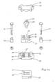
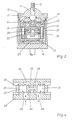
- Fig. 1 einen Längsschnitt durch eine bevorzugte Ausführungsform eines erfindungsgemäßen sanitären Mischventils,
- Fig. 1a in einer Explosionsdarstellung, die feststehende Ventilsitzscheibe, die untere Führungsscheibe, die Regelscheibe, das temperaturabhängige Regelelement und die obere Führungsscheibe des sanitären Mischventils nach Fig. 1,
- Fig. 2 einen Schnitt durch das sanitäre Mischventil nach Fig. 1 längs der Linie II - II,
- Fig. 3a jeweils von oben gesehen, die Ventilsitzscheibe, die untere Führungsscheibe, die Regelscheibe und die obere Führungsscheibe des sanitären Mischventils nach Fig. 1, die Regelscheibe geringfügig gegenüber der Darstellung in Fig. 1a geändert,
- Fig. 3b jeweils von unten gesehen, die Ventilsitzscheibe, die untere Führungsscheibe, die Regelscheibe und die obere Führungsscheibe, die in Fig. 3a von oben gesehen dargestellt sind, und
- Fig. 4 schematisch, das aus der unteren Führungsscheibe, der Regelscheibe und der oberen Führungsscheibe bestehende Scheibenpaket mit den realisierten Wasserwegen.
- 1 shows a longitudinal section through a preferred embodiment of a sanitary mixing valve according to the invention,
- 1a in an exploded view, the fixed valve seat plate, the lower guide plate, the control plate, the temperature-dependent control element and the upper guide plate of the sanitary mixing valve according to FIG. 1,
- 2 shows a section through the sanitary mixing valve according to FIG. 1 along the line II-II,
- 3a each seen from above, the valve seat disk, the lower guide disk, the regulating disk and the upper guide disk of the sanitary mixing valve according to FIG. 1, the regulating disk changed slightly compared to the illustration in FIG. 1a,
- 3b each seen from below, the valve seat disc, the lower guide disc, the regulating disc and the upper guide disc, which are shown in FIG. 3a seen from above, and
- Fig. 4 schematically, the disc package consisting of the lower guide disc, the regulating disc and the upper guide disc with the waterways implemented.
Das in den Fig. 1 und 2 dargestellte sanitäre Mischventil weist zunächst einen Ventilkörper 10 mit einem Wasserauslauf 11 und ein Betätigungsorgan mit einem Betätigungshebel 12 und einem auf den Betätigungshebel 12 aufsetzbaren, nicht dargestellten Betätigungsgriff auf. In den Ventilkörper 10 ist ein Kartuschengehäuse 13 eingesetzt. Oberhalb des Kartuschengehäuses 13 ist ein Ventilkörperdeckel 14 vorgesehen, der mittels eines Halteringes 15 im Ventilkörper 10 festgelegt ist. Der Ventilkörperdeckel 14 weist eine Betätigungsöffnung 16 auf, durch die der Betätigungshebel 12 greift. Am Fuß der Betätigungsöffnung 16 ist ein 0-Ring 17 vorgesehen, so daß der Betätigungshebel 12 abgedichtet beweglich ist. Am Boden des Ventilkörpers 10 sind eine Warmwasserzuleitung 18 und eine Kaltwasserzuleitung 19 angeschlossen. Zu den die Warmwasserzuleitung 18 und die Kaltwasserzuleitung 19 aufnehmenden Durchtrittsöffnungen im Boden des Ventilkörpers 10 korrespondieren Durchtrittsöffnungen im Boden des Kartuschengehäuses 13. In den im Boden des Kartuschengehäuses 13 vorgesehenen Durchtrittsöffnungen sind Dichtungen 18′ und 19′ eingesetzt.The sanitary mixing valve shown in FIGS. 1 and 2 initially has a
Auf dem Boden des Kartuschengehäuses 13 ist zunächst eine Ventilsitzscheibe 20 mit einer Warmwassereinlauföffnung 21 und einer Kaltwassereinlauföffnung 22 festgelegt. Auf der Ventilsitzscheibe 20 ist ein Scheibenpaket angeordnet, das insgesamt zur Mengensteuerung mit Hilfe des Betätigungsorgans, also mit Hilfe des Betätigungshebels 12 gegenüber der Ventilsitzscheibe 20 verschiebbar ist. Das Scheibenpaket besteht aus einer unteren Führungsscheibe 23, einer oberen Führungsscheibe 24 und einer zwischen der unteren Führungsscheibe 23 und der oberen Führungsscheibe 24 vorgesehenen Regelscheibe 25. Die untere Führungsscheibe 23 weist mit der Warmwassereinlauföffnung 21 und der Kaltwassereinlauföffnung 22 der Ventilsitzscheibe 20 kommunizierende Durchtrittsöffnungen 28, 29 auf, denen in der Regelscheibe 25 Durchtrittsöffnungen 33, 34 zugeordnet sind, - so daß auch die Durchtrittsöffnungen 33, 34 der Regelscheibe 25 - in Abhängigkeit von der Stellung des Scheibenpakets zur Ventilsitzscheibe 20 - mit der Warmwassereinlauföffnung 21 und der Kaltwassereinlauföffnung 22 in der Ventilsitzscheibe 20 kommunizieren können. Des weiteren ist die obere Führungsscheibe 24 mit den Durchtrittsöffnungen 33, 34 der Regelscheibe 25 zugeordneten Druckausgleichskammern 36 versehen. Die Druckausgleichskammern 36 der oberen Führungsscheibe 24 können - in Abhängigkeit von der Stellung der Regelscheibe 25 - mit den Durchtrittsöffnungen 33, 34 der Regelscheibe und den Durchtrittsöffnungen 28, 29 der unteren Führungsscheibe 23 und - in Abhängigkeit von der Stellung des Scheibenpakets relativ zur Ventilsitzscheibe 20 - mit der Warmwassereinlauföffnung 21 und der Kaltwassereinlauföffnung 22 in der Ventilsitzscheibe 20 kommunizieren. Schließlich ist als weiteres funktionsnotwendiges Bauelement noch ein temperaturabhängiges Regelelement 39 vorgesehen.A
Wie bereits ausgeführt, ist die Regelscheibe 25 zur Temperatursteuerung mittels des Betätigungsorgans, also mittels des Betätigungshebels 12 relativ zu den Führungsscheiben 23, 24 in eine temperaturbestimmende Ausgangsstellung einstellbar. Darüber hinaus ist die Regelscheibe 25 zur Temperaturregelung mittels des temperaturabhängigen Regelelements 39 relativ zu den Führungsscheiben 23, 24 steuerbar.As already stated, the regulating
Bei dem in Rede stehenden sanitären Mischventil ist also einerseits eine Mengensteuerung, andererseits eine Temperatursteuerung und -regelung verwirklicht. Die Mengensteuerung erfolgt durch eine lineare Verschiebung des gesamten Scheibenpakets relativ zu der Ventilsitzscheibe 20, und zwar mit Hilfe des Betätigungsorgans und damit mit Hilfe des Betätigungshebels 12. Die Temperatursteuerung erfolgt ebenfalls durch eine lineare Verschiebung, und zwar der Regelscheibe 25 relativ zu den Führungsscheiben 23, 24, wiederum mit Hilfe des Betätigungsorgans und damit mit Hilfe des Betätigungshebels 12. Die Temperaturregelung schließlich erfolgt auch durch eine lineare Verschiebung, und zwar, wie bei der Temperatursteuerung, durch eine lineare Verschiebung der Regelscheibe 25 relativ zu den Führungsscheiben 23, 24, jedoch mit Hilfe des temperaturabhängigen Regelelements 39.In the sanitary mixing valve in question, quantity control is implemented on the one hand, and temperature control and regulation on the other hand. The quantity is controlled by a linear displacement of the entire disc package relative to the
Erfindungsgemäß ist in der Regelscheibe mindestens eine mit den Durchtrittsöffnungen der unteren Führungsscheibe und/oder mit den Druckausgleichskammern der oberen Führungsscheibe kommunizierende Mischkammer vorgesehen und das temperaturabhängige Regelelement in der Mischkammer der Regelscheibe und/oder in einer mit der Mischkammer kommunizierenden Ausnehmung der Regelscheibe angeordnet. Für das dargestellte Ausführungsbeispiel gilt, wie insbesondere die Fig. 1, 1a, 3a und 3b zeigen, daß in der Regelscheibe 25 eine mit den Durchtrittsöffnungen 28, 29 der unteren Führungsscheibe 23 kommunizierende Mischkammer 35 und eine mit den Druckausgleichskammern 36 der oberen Führungsscheibe 24 kommunizierende Mischkammer 35 vorgesehen sind, die beiden Mischkammern 35 in eine Ausnehmung 32 der Regelscheibe 25 münden und das temperaturabhängige Regelelement 39 in der Ausnehmung 32 der Regelscheibe 25 angeordnet ist. Im übrigen ist, wie nur in Fig. 2 angedeutet, in die Mischkammern 35 Gewebematerial eingelegt, das einerseits der besseren Durchmischung des kalten Wassers und des warmen Wassers dient, andererseits eine Geräuschreduzierung bewirkt.According to the invention, at least one mixing chamber communicating with the through openings of the lower guide disk and / or with the pressure compensation chambers of the upper guide disk is provided and the temperature-dependent control element is arranged in the mixing chamber of the control disk and / or in a recess of the control disk communicating with the mixing chamber. 1, 1a, 3a and 3b show that in the regulating disk 25 a
Im dargestellten Ausführungsbeispiel weisen die untere Führungsscheibe 23 und die Regelscheibe 25 jeweils vier Durchtrittsöffnungen 28 bzw. 29 und 33 bzw. 34 auf und kommunizieren jeweils zwei Durchtrittsöffnungen 28 bzw. 29 der unteren Führungsscheibe 23 mit der Warmwassereinlauföffnung 21 bzw. der Kaltwassereinlauföffnung 22 der Ventilsitzscheibe 20. Im einzelnen weist die untere Führungsscheibe 23 auf ihrer der Ventilsitzscheibe 20 zugewandten Seite der Warmwassereinlauföffnung 21 und der Kaltwassereinlauföffnung 22 der Ventilsitzscheibe 20 zugeordnete Einlaufschlitze 26, 27 auf und geht von den äußeren Enden der Einlaufschlitze 26, 27 jeweils eine Durchtrittsöffnung 28, 29 ab (vgl. Fig. 3b). Die Durchtrittsöffnungen 28, 29 der unteren Führungsscheibe 23 weisen auf ihrer der Regelscheibe 25 zugewandten Seite Erweiterungen 30 auf (vgl. Fig. 3a), die mit den unteren Mischkammern 35 der Regelscheibe 25 kommunizieren. Da im dargestellten Ausführungsbeispiel die untere Führungsscheibe 23 und die Regelscheibe 25 jeweils vier Durchtrittsöffnungen 28 bzw. 29 und 33 bzw. 34 aufweisen, weist die obere Führungsscheibe 24 auf ihrer der Regelscheibe 25 zugewandten Seite vier Druckausgleichskammern 36 auf, nämlich den vier Durchtrittsöffnungen 33, 34 der Regelscheibe 25 zugeordnete Druckausgleichskammern 36 (vgl. Fig. 3b).In the exemplary embodiment shown, the
Für das dargestellte Ausführungsbeispiel eines erfindungsgemäßen sanitären Mischventils gilt weiter, daß die untere Führungsscheibe 23 und die obere Führungsscheibe 24 auf ihren der Regelscheibe 25 zugewandten Seiten jeweils - weitere - Druckausgleichskammern 37 für Teilmengen des kalten Wassers und des warmen Wassers aufweisen und die Druckausgleichskammern 37 auf den äußeren Begrenzungskanten der unteren Führungsscheibe 23 und der oberen Führungsscheibe 24 vorgesehen und nach außen offen sind.For the illustrated embodiment of a sanitary mixing valve according to the invention, the
Im dargestellten Ausführungsbeispiel ist, wie insbesondere die Fig. 1 und 1a zeigen, das temperaturabhängige Regelelement 39 zylindrisch ausgebildet und mit einem Kolben 40 versehen und ist, wie die Fig. 1a, 3a und 3b zeigen, die Regelscheibe 25 U-förmig ausgeführt, wobei die U-Schenkel 31 die Ausnehmung 32 begrenzen und in den U-Schenkeln 31 die Durchtrittsöffnungen 33 und 34 sowie die Mischkammern 35 ausgebildet sind.In the illustrated embodiment, as shown in FIGS. 1 and 1a in particular, the temperature-
Eingangs ist bereits ausgeführt, daß bei dem erfindungsgemäßen sanitären Mischventil die untere Führungsscheibe 23, die obere Führungsscheibe 24 und die Regelscheibe 25 ein Scheibenpaket bilden. Wie dazu die Fig. 1a zeigt, sind die untere Führungsscheibe 23 und die obere Führungsscheibe 24 - mit Hilfe von Durchtrittsöffnungen 50 in den Führungsscheiben 23, 24 durchdringenden Schrauben 51 - unter Zwischenschaltung von Abstandshülsen 52 gegeneinander verspannt, wobei die Länge der Abstandshülsen 52 den für die Verschiebbarkeit der Regelscheibe 25 erforderlichen Abstand zwischen der unteren Führungsscheibe 23 und der oberen Führungsscheibe 24 sicherstellt.It has already been stated at the outset that in the sanitary mixing valve according to the invention the
In bezug auf das temperaturabhängige Regelelement 39 ist noch darauf hinzuweisen, daß, wie die Figuren 1 und 2 zeigen, ein das Scheibenpaket übergreifender Bügel 41 vorgesehen ist und zwischen den beiden Bügelschenkeln 42, 43 eine Rückstellfeder 44, die Regelscheibe 25 und das temperaturabhängige Regelelement 39 eingespannt sind. Im einzelnen stützen sich ab die Rückstellfeder 44 am Bügelschenkel 42, die Regelscheibe 25 an der Rückstellfeder 44 und das temperaturabhängige Regelelement 39 einerseits an der Regelscheibe 25 und andererseits - mit seinem Kolben 40 - am Bügelschenkel 43, und zwar an einer am Bügelschenkel 43 vorgesehenen Einstellschraube. Der Bügel 41 ist auf einem formschlüssig mit dem Scheibenpaket festgelegten Steuerkäfig 45 verschiebbar. Dazu greift ein Steuernocken 46 des Betätigungshebels 12 in eine entsprechende Ausnehmung des Bügels 41 ein, wobei der Steuernocken 46 des Betätigungshebels 12 einen Exzenter aufweist, so daß eine Drehbewegung des Betätigungshebels 12 und damit eine Drehbewegung des Steuernockens 46 in eine lineare Verschiebung des Bügels 41 umgesetzt wird. Der Steuernocken 46 des Betätigungshebels 12 und die zugeordnete Ausnehmung des Bügels 41 sind so ausgelegt, daß sich eine sog. Komfortzone ergibt, bei der eine relativ große Drehung des Betätigungshebels 12 nur eine geringe Verschiebung des Bügels 41 und damit eine geringe Änderung der Temperatureinstellung zur Folge hat.With regard to the temperature-
Bei dem erfindungsgemäßen sanitären Mischventil wird eine Teilmenge des kalten Wassers und des warmen Wassers in der Regelscheibe 25 selbst gemischt, und zwar in den Mischkammern 35, und das Mischwasser auf kurzem Wege unmittelbar an das temperaturabhängige Regelelement 39 gebracht, so daß bei Abweichungen der Mischwassertemperatur von der eingestellten Mischwassertemperatur sofort eine vom Regelelement 39 ausgelöste Steuerung der Regelscheibe 25 relativ zu den beiden Führungsscheiben 23, 24 erfolgt.In the sanitary mixing valve according to the invention, a portion of the cold water and the warm water is mixed in the
Da im dargestellten Ausführungsbeispiel des erfindungsgemäßen sanitären Mischventils die untere Führungsscheibe 23 und die obere Führungsscheibe 24 auf ihren der Regelscheibe 25 zugewandten Seiten Druckausgleichskammern 37 für Teilmengen des kalten Wassers und des warmen Wassers aufweisen, also Druckausgleichskammern 37 aufweisen, die nicht mit den Mischkammern 35 der Regelscheibe 25 kommunizieren, besteht die Möglichkeit, durch eine entsprechende Dimensionierung der Querschnitte die Teilmengen des kalten und des warmen Wassers, die in die Mischkammern 35 der Regelscheibe 25 gelangen, und die Teilmengen des kalten Wassers und des warmen Wassers, die nicht in die Mischkammern 35 der Regelscheibe 25 gelangen, zueinander festzulegen und damit das Regelverhalten zu bestimmen. Im übrigen kommen natürlich alle Teilmengen des kalten Wassers und des warmen Wassers im Wasserraum 38 des erfindungsgemäßen sanitäten Mischventils zusammen. Im Wasserraum 38 findet dann eine weitere Mischung des insgesamt zugeführten Wassers statt, bevor dieses das sanitäre Mischventil über den Wasserauslauf 11 verläßt.Since in the illustrated embodiment of the sanitary mixing valve according to the invention, the
Der Wasserlauf durch das erfindungsgemäße sanitäre Mischventil stellt sich folgendermaßen dar:The water flow through the sanitary mixing valve according to the invention is as follows:
Schwenkbewegungen des Betätigungsorgans und damit des Betätigungshebels 12 in der Ebene des Wasserauslaufes 11 bewirken eine Mengensteuerung des durch das Mischventil strömenden Wassers, nämlich dadurch, daß das Scheibenpaket wegen seiner über den Steuerkäfig 45 verwirklichten formschlüssigen Verbindung mit dem Steuernocken 46 des Betätigungshebels 12 auf der Ventilsitzscheibe 20 verschoben wird. Hierbei wirken die Einlaufschlitze 26, 27 der unteren Führungsscheibe 23 mit der Warmwassereinlauföffnung 21 und der Kaltwassereinlauföffnung 22 der Ventilsitzscheibe 20 zusammen, so daß je nach der Stellung des Scheibenpakets relativ zu der Ventilsitzscheibe 20 eine entsprechende Wassermenge durch das Mischventil strömen kann.Swiveling movements of the actuating member and thus of the actuating
Die Temperatursteuerung erfolgt durch eine Drehung des Betätigungsorgans und damit durch eine Drehung des Betätigungshebels 12, wobei die Drehung des Betätigungshebels 12 über den Steuernocken 46 in eine lineare Verschiebung des Bügels 41 und damit in eine lineare Verschiebung der Regelscheibe 25 relativ zu den Führungsscheiben 23, 24 umgesetzt wird. Die relative Lage der Regelscheibe 25 in bezug auf die Führungsscheiben 23 und 24 bestimmt die Mischwassertemperatur.The temperature is controlled by rotating the actuating member and thus by rotating the actuating
Teilmengen des kalten Wassers und des warmen Wassers treten in die den Führungsscheiben 23, 24 zugekehrten Mischkammern 35 der Regelscheibe 25 ein. Von den Mischkammern 35 her umströmt das Mischwasser das in der Regelscheibe 25 angeordnete temperaturabhängige Regelelement. Das temperaturabhängige Regelelement 39 steuert über den auf Temperaturänderungen ansprechenden Kolben 40 die Lage der Regelscheibe 25 relativ zu den Führungsscheiben 23, 24.Portions of the cold water and the warm water enter the mixing
Claims (10)
Priority Applications (1)
| Application Number | Priority Date | Filing Date | Title |
|---|---|---|---|
| AT89109203T ATE62081T1 (en) | 1988-05-20 | 1989-05-22 | SANITARY MIXING VALVE WITH THERMOSTAT CONTROL. |
Applications Claiming Priority (2)
| Application Number | Priority Date | Filing Date | Title |
|---|---|---|---|
| DE3817277A DE3817277A1 (en) | 1988-05-20 | 1988-05-20 | SANITARY MIXER MIXER WITH THERMOSTAT CONTROL |
| DE3817277 | 1988-05-20 |
Publications (2)
| Publication Number | Publication Date |
|---|---|
| EP0342709A1 true EP0342709A1 (en) | 1989-11-23 |
| EP0342709B1 EP0342709B1 (en) | 1991-03-27 |
Family
ID=6354824
Family Applications (1)
| Application Number | Title | Priority Date | Filing Date |
|---|---|---|---|
| EP89109203A Expired - Lifetime EP0342709B1 (en) | 1988-05-20 | 1989-05-22 | Sanitary mixing valve using thermostatic control |
Country Status (15)
| Country | Link |
|---|---|
| US (1) | US5110044A (en) |
| EP (1) | EP0342709B1 (en) |
| JP (1) | JP2703082B2 (en) |
| KR (1) | KR920006936B1 (en) |
| AT (1) | ATE62081T1 (en) |
| BR (1) | BR8907432A (en) |
| CA (1) | CA1332389C (en) |
| DE (2) | DE3817277A1 (en) |
| DK (1) | DK244589A (en) |
| ES (1) | ES2021889B3 (en) |
| FI (1) | FI89830C (en) |
| GR (1) | GR3001988T3 (en) |
| MX (1) | MX173940B (en) |
| TR (2) | TR23689A (en) |
| WO (1) | WO1989011690A1 (en) |
Cited By (1)
| Publication number | Priority date | Publication date | Assignee | Title |
|---|---|---|---|---|
| FR2801957A1 (en) | 1999-12-03 | 2001-06-08 | Watts Eurotherm Sa | FLUID FLOW CONTROL DEVICE LOCATED IN A THERMOSTATIC VALVE |
Families Citing this family (20)
| Publication number | Priority date | Publication date | Assignee | Title |
|---|---|---|---|---|
| US5427312A (en) * | 1994-01-14 | 1995-06-27 | Simonov; Alexander | Thermostatic mixing valve and method of use thereof |
| DE4423853C2 (en) * | 1994-07-07 | 2002-10-24 | Hansgrohe Ag | Einhebelmischventil |
| PT102734A (en) * | 2002-03-01 | 2003-09-30 | Euroexpor Equip Metal Nao Meta | DOUBLE CONTROL THERMOSTATIC MIXER |
| US7406980B2 (en) | 2005-08-29 | 2008-08-05 | Masco Corporation Of Indiana | Waterway connection |
| US7415991B2 (en) * | 2005-12-20 | 2008-08-26 | Masco Corporation Of Indiana | Faucet spout with water isolating couplings |
| US7766043B2 (en) | 2006-05-26 | 2010-08-03 | Masco Corporation Of Indiana | Faucet including a molded waterway assembly |
| US8991425B2 (en) | 2006-05-26 | 2015-03-31 | Delta Faucet Company | Waterway assembly including an overmolded support plate |
| US7717133B2 (en) * | 2007-01-31 | 2010-05-18 | Masco Corporation Of Indiana | Spout tip attachment |
| US7806141B2 (en) * | 2007-01-31 | 2010-10-05 | Masco Corporation Of Indiana | Mixing valve including a molded waterway assembly |
| US20080178957A1 (en) * | 2007-01-31 | 2008-07-31 | Masco Corporation Of Indiana | Tube assembly |
| US7748409B2 (en) * | 2007-01-31 | 2010-07-06 | Masco Corporation Of Indiana | Overmold interface for fluid carrying system |
| WO2009126887A1 (en) | 2008-04-10 | 2009-10-15 | Masco Corporation Of Indiana | Molded waterway for a two handle faucet |
| WO2009158497A1 (en) * | 2008-06-25 | 2009-12-30 | Masco Corporation Of Indiana | Centerset faucet with mountable spout |
| US8104512B2 (en) | 2008-09-25 | 2012-01-31 | Masco Corporation Of Indiana | Spout tip retention method |
| US8739826B2 (en) | 2011-03-11 | 2014-06-03 | Masco Corporation Of Indiana | Centerset faucet body and method of making same |
| KR101279861B1 (en) | 2011-08-29 | 2013-06-28 | 신현오 | a faucet with a balance supply temperature of water |
| US8931500B2 (en) | 2012-02-17 | 2015-01-13 | Masco Corporation Of Indiana | Two handle centerset faucet |
| JP6323653B2 (en) * | 2013-12-26 | 2018-05-16 | Toto株式会社 | Hot water mixing valve device |
| FR3054282B1 (en) * | 2016-07-21 | 2018-08-31 | Vernet | MIXING UNIT AND MIXER TAP COMPRISING SUCH A MIXING UNIT |
| GB2560377B (en) * | 2017-03-10 | 2019-10-16 | Ideal Standard Int Nv | Single hole basin fitting with a thermostatic mixing cartridge and a manifold |
Citations (3)
| Publication number | Priority date | Publication date | Assignee | Title |
|---|---|---|---|---|
| GB2089003A (en) * | 1980-11-07 | 1982-06-16 | Knebel & Roettger Fa | Thermostatically controlled mixer valve |
| US4381073A (en) * | 1980-05-20 | 1983-04-26 | Roland Gloor | Thermostatically controlled cold and hot water mixer |
| US4738393A (en) * | 1986-07-14 | 1988-04-19 | American Standard Inc. | Mixing valve assembly |
Family Cites Families (7)
| Publication number | Priority date | Publication date | Assignee | Title |
|---|---|---|---|---|
| FR2295327A1 (en) * | 1974-12-20 | 1976-07-16 | Pont A Mousson | THERMOSTATIC MIXING VALVE |
| DE2804803A1 (en) * | 1978-02-04 | 1979-08-09 | Hansa Metallwerke Ag | Thermostatic control for water mixer valve - has two adjacent discs operated by lever to determine hot to cold ratio |
| DE2928330C2 (en) * | 1979-07-13 | 1982-06-09 | Friedrich Grohe Armaturenfabrik Gmbh & Co, 5870 Hemer | Mixer tap |
| DE3546504A1 (en) * | 1985-07-13 | 1987-03-19 | Ideal Standard | Sanitary mixer tap |
| DE3531194C1 (en) * | 1985-08-31 | 1986-12-18 | Knebel & Röttger GmbH & Co, 5860 Iserlohn | Sanitary mixing valve |
| DE3531295A1 (en) * | 1985-09-02 | 1987-03-19 | Knebel & Roettger Fa | SANITARY MIXING TAP |
| FR2625788B1 (en) * | 1988-01-11 | 1990-04-27 | Prod Sanitaires Cie Internal | THERMOSTATIC MIXER VALVE |
-
1987
- 1987-06-05 TR TR87/0395A patent/TR23689A/en unknown
-
1988
- 1988-05-20 DE DE3817277A patent/DE3817277A1/en active Granted
-
1989
- 1989-05-19 BR BR898907432A patent/BR8907432A/en not_active Application Discontinuation
- 1989-05-19 FI FI892433A patent/FI89830C/en not_active IP Right Cessation
- 1989-05-19 KR KR1019900700101A patent/KR920006936B1/en not_active IP Right Cessation
- 1989-05-19 WO PCT/EP1989/000548 patent/WO1989011690A1/en unknown
- 1989-05-19 JP JP1505481A patent/JP2703082B2/en not_active Expired - Fee Related
- 1989-05-19 US US07/623,383 patent/US5110044A/en not_active Expired - Fee Related
- 1989-05-19 CA CA000600303A patent/CA1332389C/en not_active Expired - Fee Related
- 1989-05-19 DK DK244589A patent/DK244589A/en not_active Application Discontinuation
- 1989-05-19 MX MX016120A patent/MX173940B/en unknown
- 1989-05-22 DE DE8989109203T patent/DE58900070D1/en not_active Expired - Fee Related
- 1989-05-22 TR TR89/0395A patent/TR23637A/en unknown
- 1989-05-22 ES ES89109203T patent/ES2021889B3/en not_active Expired - Lifetime
- 1989-05-22 AT AT89109203T patent/ATE62081T1/en not_active IP Right Cessation
- 1989-05-22 EP EP89109203A patent/EP0342709B1/en not_active Expired - Lifetime
-
1991
- 1991-05-22 GR GR91400665T patent/GR3001988T3/en unknown
Patent Citations (3)
| Publication number | Priority date | Publication date | Assignee | Title |
|---|---|---|---|---|
| US4381073A (en) * | 1980-05-20 | 1983-04-26 | Roland Gloor | Thermostatically controlled cold and hot water mixer |
| GB2089003A (en) * | 1980-11-07 | 1982-06-16 | Knebel & Roettger Fa | Thermostatically controlled mixer valve |
| US4738393A (en) * | 1986-07-14 | 1988-04-19 | American Standard Inc. | Mixing valve assembly |
Cited By (1)
| Publication number | Priority date | Publication date | Assignee | Title |
|---|---|---|---|---|
| FR2801957A1 (en) | 1999-12-03 | 2001-06-08 | Watts Eurotherm Sa | FLUID FLOW CONTROL DEVICE LOCATED IN A THERMOSTATIC VALVE |
Also Published As
| Publication number | Publication date |
|---|---|
| WO1989011690A1 (en) | 1989-11-30 |
| FI89830B (en) | 1993-08-13 |
| CA1332389C (en) | 1994-10-11 |
| BR8907432A (en) | 1991-04-02 |
| JPH03504264A (en) | 1991-09-19 |
| KR920006936B1 (en) | 1992-08-22 |
| FI892433A (en) | 1989-11-21 |
| US5110044A (en) | 1992-05-05 |
| DE58900070D1 (en) | 1991-05-02 |
| TR23637A (en) | 1990-05-21 |
| DK244589A (en) | 1989-11-21 |
| JP2703082B2 (en) | 1998-01-26 |
| DK244589D0 (en) | 1989-05-19 |
| TR23689A (en) | 1990-06-13 |
| KR900702441A (en) | 1990-12-07 |
| DE3817277A1 (en) | 1989-11-30 |
| ES2021889B3 (en) | 1991-11-16 |
| MX173940B (en) | 1994-04-11 |
| EP0342709B1 (en) | 1991-03-27 |
| FI892433A0 (en) | 1989-05-19 |
| ATE62081T1 (en) | 1991-04-15 |
| FI89830C (en) | 1993-11-25 |
| GR3001988T3 (en) | 1992-11-23 |
| DE3817277C2 (en) | 1990-03-08 |
Similar Documents
| Publication | Publication Date | Title |
|---|---|---|
| EP0342709B1 (en) | Sanitary mixing valve using thermostatic control | |
| DE2658022C3 (en) | Mixer tap for the sanitary compartment | |
| DE3531295C2 (en) | ||
| EP0238674B1 (en) | Sanitary mixing valve | |
| DE3612988A1 (en) | MIXED BATTERY | |
| CH651642A5 (en) | THERMOSTAT CONTROLLED MIXER BATTERY. | |
| DE4208241A1 (en) | THERMOSTATICALLY CONTROLLED MIXING VALVE | |
| DE60319751T2 (en) | THERMOSTATIC MIXING VALVE | |
| EP0647337B1 (en) | Sanitary mixer tap with thermostat control | |
| DE60302941T2 (en) | One arm thermostatic cartridge with ceramic discs | |
| DE112017000696T5 (en) | Assembly for producing a cartridge for controlling cold and warm fluids to be mixed | |
| DE3118003C2 (en) | Thermostat controlled mixer for cold and hot water | |
| WO1994021948A1 (en) | Sanitary mixer tap | |
| DE19901851A1 (en) | Cartridge for sanitary fittings | |
| EP1022637B1 (en) | Thermostatic valve | |
| DE10006375A1 (en) | Temperature controlled mixing valve | |
| DE3043089A1 (en) | MECHANICALLY ACTUATED HOT WATER MIXER | |
| DE2930276A1 (en) | Thermostatically controlled mixer valve - uses two bimetallic spring washer stacks and double taper valve piston | |
| DE3239772C2 (en) | ||
| DE10115641A1 (en) | Sanitary thermostatic valve | |
| DE1475980C (en) | Thermally controlled mixing valve | |
| DE1476417C (en) | Thermostatically controlled control valve for the cooling circuit of internal combustion engines | |
| CH646764A5 (en) | Mixing valve, especially for the sanitary sector | |
| DE1475980B1 (en) | Thermally controlled mixing valve | |
| WO2008135218A1 (en) | Control cartridge for a mixing faucet, comprising a noise-reducing insert |
Legal Events
| Date | Code | Title | Description |
|---|---|---|---|
| PUAI | Public reference made under article 153(3) epc to a published international application that has entered the european phase |
Free format text: ORIGINAL CODE: 0009012 |
|
| AK | Designated contracting states |
Kind code of ref document: A1 Designated state(s): AT BE CH DE ES FR GB GR IT LI NL SE |
|
| 17P | Request for examination filed |
Effective date: 19891125 |
|
| 17Q | First examination report despatched |
Effective date: 19900419 |
|
| GRAA | (expected) grant |
Free format text: ORIGINAL CODE: 0009210 |
|
| AK | Designated contracting states |
Kind code of ref document: B1 Designated state(s): AT BE CH DE ES FR GB GR IT LI NL SE |
|
| REF | Corresponds to: |
Ref document number: 62081 Country of ref document: AT Date of ref document: 19910415 Kind code of ref document: T |
|
| ET | Fr: translation filed | ||
| REF | Corresponds to: |
Ref document number: 58900070 Country of ref document: DE Date of ref document: 19910502 |
|
| ITF | It: translation for a ep patent filed |
Owner name: ING. C. CORRADINI & C. S.R.L. |
|
| GBT | Gb: translation of ep patent filed (gb section 77(6)(a)/1977) | ||
| PLBE | No opposition filed within time limit |
Free format text: ORIGINAL CODE: 0009261 |
|
| STAA | Information on the status of an ep patent application or granted ep patent |
Free format text: STATUS: NO OPPOSITION FILED WITHIN TIME LIMIT |
|
| 26N | No opposition filed | ||
| REG | Reference to a national code |
Ref country code: GR Ref legal event code: FG4A Free format text: 3001988 |
|
| PGFP | Annual fee paid to national office [announced via postgrant information from national office to epo] |
Ref country code: AT Payment date: 19930428 Year of fee payment: 5 |
|
| PGFP | Annual fee paid to national office [announced via postgrant information from national office to epo] |
Ref country code: BE Payment date: 19930504 Year of fee payment: 5 |
|
| PGFP | Annual fee paid to national office [announced via postgrant information from national office to epo] |
Ref country code: FR Payment date: 19930507 Year of fee payment: 5 |
|
| PGFP | Annual fee paid to national office [announced via postgrant information from national office to epo] |
Ref country code: GR Payment date: 19930510 Year of fee payment: 5 |
|
| PGFP | Annual fee paid to national office [announced via postgrant information from national office to epo] |
Ref country code: CH Payment date: 19930524 Year of fee payment: 5 |
|
| PGFP | Annual fee paid to national office [announced via postgrant information from national office to epo] |
Ref country code: NL Payment date: 19930531 Year of fee payment: 5 |
|
| PGFP | Annual fee paid to national office [announced via postgrant information from national office to epo] |
Ref country code: SE Payment date: 19930723 Year of fee payment: 5 |
|
| PG25 | Lapsed in a contracting state [announced via postgrant information from national office to epo] |
Ref country code: AT Effective date: 19940522 |
|
| PG25 | Lapsed in a contracting state [announced via postgrant information from national office to epo] |
Ref country code: SE Free format text: THE PATENT HAS BEEN ANNULLED BY A DECISION OF A NATIONAL AUTHORITY Effective date: 19940530 |
|
| PG25 | Lapsed in a contracting state [announced via postgrant information from national office to epo] |
Ref country code: LI Effective date: 19940531 Ref country code: CH Effective date: 19940531 Ref country code: BE Effective date: 19940531 |
|
| BERE | Be: lapsed |
Owner name: IDEAL-STANDARD G.M.B.H. Effective date: 19940531 |
|
| PG25 | Lapsed in a contracting state [announced via postgrant information from national office to epo] |
Ref country code: GR Free format text: THE PATENT HAS BEEN ANNULLED BY A DECISION OF A NATIONAL AUTHORITY Effective date: 19941130 |
|
| PG25 | Lapsed in a contracting state [announced via postgrant information from national office to epo] |
Ref country code: NL Effective date: 19941201 |
|
| NLV4 | Nl: lapsed or anulled due to non-payment of the annual fee | ||
| EUG | Se: european patent has lapsed |
Ref document number: 89109203.3 Effective date: 19941210 |
|
| PG25 | Lapsed in a contracting state [announced via postgrant information from national office to epo] |
Ref country code: FR Effective date: 19950131 |
|
| REG | Reference to a national code |
Ref country code: CH Ref legal event code: PL |
|
| EUG | Se: european patent has lapsed |
Ref document number: 89109203.3 |
|
| REG | Reference to a national code |
Ref country code: FR Ref legal event code: ST |
|
| REG | Reference to a national code |
Ref country code: GR Ref legal event code: MM2A Free format text: 3001988 |
|
| PGFP | Annual fee paid to national office [announced via postgrant information from national office to epo] |
Ref country code: GB Payment date: 19990511 Year of fee payment: 11 |
|
| PGFP | Annual fee paid to national office [announced via postgrant information from national office to epo] |
Ref country code: ES Payment date: 19990512 Year of fee payment: 11 |
|
| PGFP | Annual fee paid to national office [announced via postgrant information from national office to epo] |
Ref country code: DE Payment date: 19990528 Year of fee payment: 11 |
|
| PG25 | Lapsed in a contracting state [announced via postgrant information from national office to epo] |
Ref country code: GB Free format text: LAPSE BECAUSE OF NON-PAYMENT OF DUE FEES Effective date: 20000522 |
|
| PG25 | Lapsed in a contracting state [announced via postgrant information from national office to epo] |
Ref country code: ES Free format text: THE PATENT HAS BEEN ANNULLED BY A DECISION OF A NATIONAL AUTHORITY Effective date: 20000523 |
|
| GBPC | Gb: european patent ceased through non-payment of renewal fee |
Effective date: 20000522 |
|
| PG25 | Lapsed in a contracting state [announced via postgrant information from national office to epo] |
Ref country code: DE Free format text: LAPSE BECAUSE OF NON-PAYMENT OF DUE FEES Effective date: 20010301 |
|
| REG | Reference to a national code |
Ref country code: ES Ref legal event code: FD2A Effective date: 20020204 |
|
| PG25 | Lapsed in a contracting state [announced via postgrant information from national office to epo] |
Ref country code: IT Free format text: LAPSE BECAUSE OF NON-PAYMENT OF DUE FEES Effective date: 20050522 |