EP0342629A1 - Method of chromatographic separation - Google Patents
Method of chromatographic separation Download PDFInfo
- Publication number
- EP0342629A1 EP0342629A1 EP89108843A EP89108843A EP0342629A1 EP 0342629 A1 EP0342629 A1 EP 0342629A1 EP 89108843 A EP89108843 A EP 89108843A EP 89108843 A EP89108843 A EP 89108843A EP 0342629 A1 EP0342629 A1 EP 0342629A1
- Authority
- EP
- European Patent Office
- Prior art keywords
- fluid
- zone
- bed
- extraction outlet
- supply inlet
- Prior art date
- Legal status (The legal status is an assumption and is not a legal conclusion. Google has not performed a legal analysis and makes no representation as to the accuracy of the status listed.)
- Granted
Links
Images
Classifications
-
- B—PERFORMING OPERATIONS; TRANSPORTING
- B01—PHYSICAL OR CHEMICAL PROCESSES OR APPARATUS IN GENERAL
- B01D—SEPARATION
- B01D15/00—Separating processes involving the treatment of liquids with solid sorbents; Apparatus therefor
- B01D15/08—Selective adsorption, e.g. chromatography
-
- B—PERFORMING OPERATIONS; TRANSPORTING
- B01—PHYSICAL OR CHEMICAL PROCESSES OR APPARATUS IN GENERAL
- B01D—SEPARATION
- B01D15/00—Separating processes involving the treatment of liquids with solid sorbents; Apparatus therefor
- B01D15/08—Selective adsorption, e.g. chromatography
- B01D15/10—Selective adsorption, e.g. chromatography characterised by constructional or operational features
- B01D15/18—Selective adsorption, e.g. chromatography characterised by constructional or operational features relating to flow patterns
- B01D15/1814—Recycling of the fraction to be distributed
- B01D15/1821—Simulated moving beds
- B01D15/1828—Simulated moving beds characterised by process features
Definitions
- the present invention relates to a method of chromatographic separation, in which a feedstock fluid and a desorbent fluid are supplied into an adsorbent-packed bed and as the feed-stock fluid moves through the bed, the components in said fluid are separated by interaction with the adsorbent and at least two fluids, one being rich in a component that interacts strongly with the adsorbent and the other being rich in a component that interacts weakly with the adsorbent, are extracted from the bed.
- Chromatographic separation is one of the separation techniques practiced extensively in industrial applications. While several techniques of chromatographic separation are known, a simulated moving-bed system has been used most extensively in large-scale operations.
- the apparatus used in a simulated moving-bed system is so adapted that a fluid stream is capable of unidirectional circulation through a bed packed with an adsorbent.
- the bed is provided with more than one set of supply inlet and extraction outlet, wherin a feed-stock fluid supply inlet, an nonadsorbate fluid extraction outlet, a desorbent fluid supply inlet and an adsorbate fluid extraction outlet are arranged in the order written in the direction of fluid flow.
- one set of supply inlet and extraction outlet is always in an active state, and as a predetermined working time lapses, this active set is switched to the next corresponding set which is located immediately downstream.
- the active set of supply inlet and extraction outlet takes a full turn around the bed and returns to its initial position.
- a unit packed bed the zone from a certain supply inlet or extraction outlet to a corresponding supply inlet or extraction outlet that is located immediately downstream is hereinafter referred to as "a unit packed bed".
- a packed bed can be regarded as a series connection of as many unit packed beds as the sets of supply inlet and extraction outlet employed.
- feedstock fluid supply inlet "desorbent fluid supply inlet”, “nonadsorbate fluid extraction outlet” and “adsorbate fluid extraction outlet” are named based on the function of an apparatus for suplying a fluid into or extracting it from the bed, and in practice, a single apparatus may have the ability to perform some of the four functions of interest. In fact, it is common practice for a single apparatus to serve both as a feedstock fluid inlet and as a desorbent fluid supply inlet, or serve both as a nonadsorbate fluid extraction outlet and as an adsorbate fluid extraction outlet.
- the zone between a feedstock fluid supply inlet and a nonadsorbate fluid extraction outlet is referred to as an adsorption zone
- the zone between the nonadsorbate fluid extraction outlet and a desorbent fluid supply inlet as a refining zone
- the zone between the desorbent fluid supply inlet and an adsorbate fluid extraction outlet as a desorption zone
- the zone between the adsorbate fluid extraction outlet and the feedstock fluid supply inlet as a concentration zone. Therefore, the packed bet consists of four zones, adsorption, refining, desorption and concentration, and each zone normally contains a plurality of unit packed beds.
- Each of the components to be separated in the packed bed forms a particular concentration distribution in the direction of feed flow and this concentration distribution, while retaining its shape, will move downstream through successive zones of the bed.
- a set of supply inlet and extraction outlet is switched to another set in synchronism with the movement of concentration distributions in such a way that a fluid can be supplied to a desired position on a particular concentration distribution while another fluid is extracted from another desired position.
- a feedstock fluid and a desorbent fluid are supplied into the bed through certain supply inlets at any point of time whereas a nonadsorbate fluid and an adsorbate fluid are extracted through certain extraction outlets, so taken as a whole, the operation can be regarded as being continuous with respect to the supply and extraction of fluids.
- the fluid to be extracted is only part of the fluid that reaches a cross section of the bed at which the outlet through which it is extracted is positioned and the greater part of the fluid will move downstream without being extracted.
- a fluid 4 ⁇ 10 times the volume of the fluid that is supplied into each zone from the outside of the bed or which is extracted from each zone to the outside of the bed will flow into each zone from one located upstream thereof. Therefore, a particular concentration distribution that is formed in the bed is capable of moving downstream without being greatly distorted in spite of fluid extraction from the bed.
- a set of supply inlet and extraction outlet is switched to an immediately downstreeam set in synchronism with the downstream movement of a particular concentration distribution formed in the bed.
- switching between adjacent sets of supply inlet and extraction outlet is intermittent and this causes a time-dependent change in the composition of a fluid being extracted through one outlet within a unit working time.
- the fluid being extracted should experience the smallest possible change in composition with time.
- the duration for which a set of supply inlet and extraction outlet is in active operation must be shortened and this set be frequently switched to successive sets of supply inlet and extraction outlet that are located downstream of the bed. But then, this requires a bed composed of many unit packed beds and the overall equipment becomes complex and costly. In consideration of its cost and the desired separation efficiency, the equipment commercially used typically consists of 6 ⁇ 24 unit packed beds.
- An object, therefore, of the present invention is to provide a method of chromatographic separation that is capable of attaining a satisfactory separation efficiency with a simpler apparatus such as one composed of four unit packed beds.
- This object of the present invetion can generally be attained by a method which performs separation of respective substances in a feedstock fluid with a chromatographic apparatus including a packed bed that is adapted to allow a fluid to flow cyclically in one direction and which is furnished with at least four sets of feedstock fluid supply inlet, nonadsorbate fluid extraction outlet, desorbent fluid supply inlet and adsorbate fluid extraction outlet, which are disposed in the order written in the direction of fluid flow, and said bed, taken as a whole, being divided into four zones by an active set of supply inlet and extraction outlet during operation, an adsorption zone occupying the space between the feedstock fluid supply inlet and the nonadsorbate fluid extraction outlet, a refining zone occupying the space between the nonadsorbate fluid extraction outlet and the desorbent fluid supply inlet, a desorption zone occupying the space between the desorbent fluid supply inlet and the adsorbate fluid extraction outlet, and a concentration zone occupying the space between the adsorbate
- the object of the present invention can specifically be attained by performing the following two steps within said predetermined working time:
- the method of the present invention is performed with an ordinary simulated moving bed (except that the number of unit packed beds in it may be smaller than in the prior art system) but the difference is in the way of operating such a conventional simulated moving bed.
- an ordinary simulated moving bed except that the number of unit packed beds in it may be smaller than in the prior art system
- the difference is in the way of operating such a conventional simulated moving bed.
- the method of the present invention differs from both the basic method of operating a simulated moving bed and from any other known methods of operation.
- a simulated moving bed consists of four zones and the adsorbate and nonadsorbate components in each zone have concentration distributions as typically shown in Fig. 2.
- the adsorbate component is present at high concentration in the desorption zone but it is not easy to move this component downstream of the bed because it interacts strongly with the packed adsorbent.
- the nonadsorbate component is predominant in the refining zone and can be readily moved downstream of the bed because its interaction with the adsorbent is weak. In this way, the ease with which a certain concentration distribution can be moved downstream varies depending upon the zone in which it is formed.
- the amount or distance the concentration distribution in each zone moves is proportional to the quantity of a fluid flowing through that zone, or the product of its flow rate (volume per time) and time. Therefore, in order to ensure that the concentration distribution in each zone is moved by the same amount, or by the width of a unit packed bed, within the duration of time for which a set of supply inlet and extraction outlet is operated, it is necessary that the quantity of the fluid flowing through each zone be adjusted to an appropriate value. For instance, the flow rate in the refining zone must be set to a value smaller than that in any other zone.
- concentration distributions in each zone are moved through two stages.
- the first stage is where a feedstock fluid and a desorbent fluid are supplied to the bed whereas a nonadsorbate fluid and an adsorbate fluid are extracted from the bed.
- the flow rate of a fluid stream differs from zone to zone as it is subject to the influences of both the rate (volume per time) at which a fluid is supplied to the bed and the rate at which a fluid is extracted from the bed.
- the second stage is where the fluid is simply allowed to flow downstream of the bed with a fluid being neither supplied into nor extracted from the bed. This stage is solely for the purpose of moving concentration distributions and the flow rate and hence, the quantity, of a fluid in each zone is held constant.
- an adsorbate fluid and a nonadsorbate fluid are extracted from the bed only at the first stage described above.
- the amounts by which concentration distributions are moved at this first stage are smaller than the total amount of movement effected when a set of supply inlet and extraction outlet is in an operational state, and therefore, the adsorbate and nonadsorbate fluids being extracted from the bed will experience a smaller time-dependent change in composition.
- the method of the present invention successfully reduces such time-dependent changes by extracting fluids in only part of the process of movement of concentration distributions.
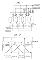
- Fig. 1 is a schemaic of a chromatographic separation apparatus that may be used in the practice of the present invention. Shown by 1 ⁇ 4 are unit beds each packed with an adsorbent; 11 is a circulation pump for circulating fluids; 21 is a flow control valve; 31 ⁇ 34 are feedstock fluid supply valves; 35 ⁇ 38 are desorbent fluid supply valves; 39 ⁇ 42 are adsorbate fluid extraction valves; and 43 ⁇ 46 are nonadsorbate fluid extraction valves.
- Fig. 2 is a diagram showing the concentration distributions of the respective components formed within the packed beds when the apparatus shown in Fig. 1 is operated by the method of the present invention.
- Fig. 2 is a diagram showing the concentration distributions of the respective components formed within the packed beds when the apparatus shown in Fig. 1 is operated by the method of the present invention.
- FIG. 2 also shows the positions at which the supply of a feedstock fluid and a desorbent fluid into the bed is started (F and W), as well as the positions at which the extraction of an adsorbate fluid and a nonadsorbate fluid from the bed is started (P and R).
- a supply and extraction step is first performed with the circulation pump 11 and flow control valve 21 being operated to circulate a predetermined amount of fluid.
- the feedstock and the desorbent are supplied through valves 31 and 37, respectively, while at the same time, the adsorbate fluid and the nonadsorbate fluid are extracted through valves 42 and 44, respectively.
- a fluid flows down the adsorption, refining, desorption and concentration zones at respective rates of R1, R2, R3 and R4 (volume per unit time), and this supply and extraction step continues for the period ⁇ 1.
- a circulation step is performed, in which only the circulation of fluid through beds is effected by means of the circulation pump 11 until the concentration distribution curves are moved to their predetermined positions.
- a fluid flows down each zone at a rate of R0 (volume per unit time), and this circulation step continues for the period ⁇ 0.
- valves 31, 37, 42 and 44 which are then switched to their corresponding valves located downstream.
- valves 32, 38, 39 and 45 which are brought to an active state for repeating the operation described above (step 2).
- the apparatus shown in Fig. 1 consists of four unit packed beds, so four valve switching operations will bring the apparatus back to its initial state.
- the valves which are opened after each switching operation, the switching times and settings of a flowmeter are shown in Table 1 below.
- the quantity of nonadsorbate fluid extracted is obviously greater than that of the feedstock fluid supplied because the quantity of the adsorbate fluid extracted simultaneously is smaller than that of the desorbent supplied and a fluid of the quanitity corresponding to that difference will flow into the adsorption zone via the concentration zone.
- This also enables the simulated moving bed to be run without violating its basic operating principle that the quantity of flow in the refining zone, R2 ⁇ 1 + R0 ⁇ 0, must be held smaller than that in the concentration zone, R4 ⁇ 1 + R0 ⁇ 0.
- Fig. 2 shows schematically which portion of the concentration distributions in the adsorption and desorption zones will be extracted from the bed.
- a fluid flows to the right as viewed in the drawing, and the concentration distribution curves are also shifted to the right.
- the concentration distribution curves are shifted and fluids are extracted from part of the width of the concentration distribution curves in the adsorption and desorption zones. Subsequently, there occurs only a shift in the concentration distribution curves in the circulation step.
- the set of supply inlet and extraction outlet located immediately downstream is activated and the procedures described above will be repeated.
- the prior art method of chromatographic separation on a simulated moving-bed system does not have a circulation step and fluids are supplied and extracted from the width of concentration curves corresponding to that of a unit packed bed. As a result, ⁇ is always maintained at unity. If the number of beds is small, the concentration at each extracting portion will vary greatly between the starting point of extraction and the end point, thereby making it difficult to produce satisfactory results. Furthermore in the case above-described, the width of each supply portion becomes large and there occurs a corresponding increase in disturbances, leading to low separation efficiency.
- the width over which fluids are supplied or extracted can be so adjusted as to ensure high separation efficiency in the presence of a small number of beds.
- a feedstock (a mixture of fructose and glucose in aqueous solution) having the composition shown in Table 2 was separated chromatographically.
- the absorbent and desorbent used were a Ca-form strongly acidic cation-exchange resin (DIAION®FRK-101 of Mitsubishi Kasei Corp.) and water, respectively.
- DIAION®FRK-101 of Mitsubishi Kasei Corp.
- R2 was adjusted to zero and in order to ensure that the pressure loss occurring in the packed bed in the supply and extraction step would be substantially equal to that occurring in the circulation step, R0 was made equal to R1.
- aqueous solution of oligosaccharide having the composition shown in Table 4 was subjected to chromatographic separation using the same apparatus as that employed in Example 1 except that a Na-form strongly acidic cation-exchange resin (DIAITON® UBK-530K) was used as an adsorbent.
- a Na-form strongly acidic cation-exchange resin DIAITON® UBK-530K
- the specific conditions of the experiment are shown in Table 5 below.
- Example 1 the experiment was conducted in order to obtain a pure product of fructose. Comparison between Tables 2 and 6 shows that the method of the present invention achieved an improvement of ca. 2 points in purity and recovery.
- Example 2 the experiment was conducted in order to obtain a pure product of DP3+. Comparison between Tables 4 and 7 shows that the method of the present invention achieved an improvement of ca. 10 points in recovery.
- the chromatographic separation method of the present invention attains results that are comparable to or better than those accomplished by a conventional simulated moving-bed system employing a greater number of beds. Therefore, the method of the present invention permits the use of a simpler apparatus and realizes a significant reduction in initial cost.
Landscapes
- Chemical & Material Sciences (AREA)
- Analytical Chemistry (AREA)
- Chemical Kinetics & Catalysis (AREA)
- Life Sciences & Earth Sciences (AREA)
- Sustainable Development (AREA)
- Treatment Of Liquids With Adsorbents In General (AREA)
Abstract
Description
- The present invention relates to a method of chromatographic separation, in which a feedstock fluid and a desorbent fluid are supplied into an adsorbent-packed bed and as the feed-stock fluid moves through the bed, the components in said fluid are separated by interaction with the adsorbent and at least two fluids, one being rich in a component that interacts strongly with the adsorbent and the other being rich in a component that interacts weakly with the adsorbent, are extracted from the bed.
- Chromatographic separation is one of the separation techniques practiced extensively in industrial applications. While several techniques of chromatographic separation are known, a simulated moving-bed system has been used most extensively in large-scale operations. The apparatus used in a simulated moving-bed system is so adapted that a fluid stream is capable of unidirectional circulation through a bed packed with an adsorbent. The bed is provided with more than one set of supply inlet and extraction outlet, wherin a feed-stock fluid supply inlet, an nonadsorbate fluid extraction outlet, a desorbent fluid supply inlet and an adsorbate fluid extraction outlet are arranged in the order written in the direction of fluid flow. During the separating operation, one set of supply inlet and extraction outlet is always in an active state, and as a predetermined working time lapses, this active set is switched to the next corresponding set which is located immediately downstream.
- Therefore, when as many switching operations as the sets of supply inlet and extraction outlet in the bed have been effected, the active set of supply inlet and extraction outlet takes a full turn around the bed and returns to its initial position. For the purpose of the following discussion, the zone from a certain supply inlet or extraction outlet to a corresponding supply inlet or extraction outlet that is located immediately downstream is hereinafter referred to as "a unit packed bed". A packed bed can be regarded as a series connection of as many unit packed beds as the sets of supply inlet and extraction outlet employed. The "feedstock fluid supply inlet", "desorbent fluid supply inlet", "nonadsorbate fluid extraction outlet" and "adsorbate fluid extraction outlet" are named based on the function of an apparatus for suplying a fluid into or extracting it from the bed, and in practice, a single apparatus may have the ability to perform some of the four functions of interest. In fact, it is common practice for a single apparatus to serve both as a feedstock fluid inlet and as a desorbent fluid supply inlet, or serve both as a nonadsorbate fluid extraction outlet and as an adsorbate fluid extraction outlet.
- With respect to a set of supply inlet and extraction outlet that is in an active state, the zone between a feedstock fluid supply inlet and a nonadsorbate fluid extraction outlet is referred to as an adsorption zone, the zone between the nonadsorbate fluid extraction outlet and a desorbent fluid supply inlet as a refining zone, the zone between the desorbent fluid supply inlet and an adsorbate fluid extraction outlet as a desorption zone, and the zone between the adsorbate fluid extraction outlet and the feedstock fluid supply inlet as a concentration zone. Therefore, the packed bet consists of four zones, adsorption, refining, desorption and concentration, and each zone normally contains a plurality of unit packed beds.
- Each of the components to be separated in the packed bed forms a particular concentration distribution in the direction of feed flow and this concentration distribution, while retaining its shape, will move downstream through successive zones of the bed. A set of supply inlet and extraction outlet is switched to another set in synchronism with the movement of concentration distributions in such a way that a fluid can be supplied to a desired position on a particular concentration distribution while another fluid is extracted from another desired position. In the basic operation of a simulated moving bed, a feedstock fluid and a desorbent fluid are supplied into the bed through certain supply inlets at any point of time whereas a nonadsorbate fluid and an adsorbate fluid are extracted through certain extraction outlets, so taken as a whole, the operation can be regarded as being continuous with respect to the supply and extraction of fluids. The fluid to be extracted is only part of the fluid that reaches a cross section of the bed at which the outlet through which it is extracted is positioned and the greater part of the fluid will move downstream without being extracted. Normally, a fluid 4 ∼ 10 times the volume of the fluid that is supplied into each zone from the outside of the bed or which is extracted from each zone to the outside of the bed will flow into each zone from one located upstream thereof. Therefore, a particular concentration distribution that is formed in the bed is capable of moving downstream without being greatly distorted in spite of fluid extraction from the bed.
- As described above, a set of supply inlet and extraction outlet is switched to an immediately downstreeam set in synchronism with the downstream movement of a particular concentration distribution formed in the bed. Although the movement of a concentration distribution is continuous, switching between adjacent sets of supply inlet and extraction outlet is intermittent and this causes a time-dependent change in the composition of a fluid being extracted through one outlet within a unit working time. In order to attain better separation performance, it is preferred that the fluid being extracted should experience the smallest possible change in composition with time. To this end, the duration for which a set of supply inlet and extraction outlet is in active operation must be shortened and this set be frequently switched to successive sets of supply inlet and extraction outlet that are located downstream of the bed. But then, this requires a bed composed of many unit packed beds and the overall equipment becomes complex and costly. In consideration of its cost and the desired separation efficiency, the equipment commercially used typically consists of 6 ∼ 24 unit packed beds.
- An object, therefore, of the present invention is to provide a method of chromatographic separation that is capable of attaining a satisfactory separation efficiency with a simpler apparatus such as one composed of four unit packed beds.
- This object of the present invetion can generally be attained by a method which performs separation of respective substances in a feedstock fluid with a chromatographic apparatus including a packed bed that is adapted to allow a fluid to flow cyclically in one direction and which is furnished with at least four sets of feedstock fluid supply inlet, nonadsorbate fluid extraction outlet, desorbent fluid supply inlet and adsorbate fluid extraction outlet, which are disposed in the order written in the direction of fluid flow, and said bed, taken as a whole, being divided into four zones by an active set of supply inlet and extraction outlet during operation, an adsorption zone occupying the space between the feedstock fluid supply inlet and the nonadsorbate fluid extraction outlet, a refining zone occupying the space between the nonadsorbate fluid extraction outlet and the desorbent fluid supply inlet, a desorption zone occupying the space between the desorbent fluid supply inlet and the adsorbate fluid extraction outlet, and a concentration zone occupying the space between the adsorbate fluid extraction outlet and the feedstock fluid supply inlet, and said active set of supply inlet and extraction outlet being switched to another set of supply inlet and extraction outlet located immediately downstream after the lapse of a predetermined working time.
- The object of the present invention can specifically be attained by performing the following two steps within said predetermined working time:
- (i) a supply and extraction step in which as part of the fluid flowing out of the desorption zone is allowed to flow into the concentration zone while the fluid flowing out of the concentration zone is allowed to flow into the adsorption zone, a feedstock fluid and a desorbent fluid are supplied into the packed bed through the feedstock fluid supply inlet and the desorbent fluid supply inlet, respectively, and at least part of the fluid flowing out of the adsorption zone is extracted from the packed bed through the nonadsorbate fluid extraction outlet, with part of the fluid flowing out of the desorption zone being extracted from the packed bed through the adsorbate fluid extraction outlet; and
- (ii) a circulation step in which the fluid in the packed bed is moved downstream without supplying a fluid into the bed or extracting a fluid from the bed.
- By performing these two steps within the predetermined working time, satisfactory separating performance can be attained in the present invention.
-
- Fig. 1 is a schematic of an apparatus suitable for use in the practice of the present invention; and
- Fig. 2 is a diagram showing concentration distributions formed within a packed bed.
- Stated more specifically, the method of the present invention is performed with an ordinary simulated moving bed (except that the number of unit packed beds in it may be smaller than in the prior art system) but the difference is in the way of operating such a conventional simulated moving bed. In accordance with the present invention:
- (i) when a feedstock fluid and a desorbent fluid are supplied into the bed and a nonadsorbate fluid and an adsorbate fluid extracted from the bed simultaneously, a portion of the fluid in the bed that has reached the position of the nonadsorbate fluid extraction outlet and which is greater than in the prior art method, sometimes the entire portion of said fluid, is extracted as a nonadsorbate fluid; and
- (ii) the fluid is supplied into or extracted from the bed intermittently; in other words, when taken as a whole, the operation of the bed includes a period during which only the fluid in the bed is moved downstream without supplying a fluid into or extracting it from the bed.
- In these two respects, the method of the present invention differs from both the basic method of operating a simulated moving bed and from any other known methods of operation.
- As already mentioned, a simulated moving bed consists of four zones and the adsorbate and nonadsorbate components in each zone have concentration distributions as typically shown in Fig. 2. The adsorbate component is present at high concentration in the desorption zone but it is not easy to move this component downstream of the bed because it interacts strongly with the packed adsorbent. On the other hand, the nonadsorbate component is predominant in the refining zone and can be readily moved downstream of the bed because its interaction with the adsorbent is weak. In this way, the ease with which a certain concentration distribution can be moved downstream varies depending upon the zone in which it is formed.
- The amount or distance the concentration distribution in each zone moves is proportional to the quantity of a fluid flowing through that zone, or the product of its flow rate (volume per time) and time. Therefore, in order to ensure that the concentration distribution in each zone is moved by the same amount, or by the width of a unit packed bed, within the duration of time for which a set of supply inlet and extraction outlet is operated, it is necessary that the quantity of the fluid flowing through each zone be adjusted to an appropriate value. For instance, the flow rate in the refining zone must be set to a value smaller than that in any other zone.
- In accordance with the present invention, concentration distributions in each zone are moved through two stages. The first stage is where a feedstock fluid and a desorbent fluid are supplied to the bed whereas a nonadsorbate fluid and an adsorbate fluid are extracted from the bed. At this stage, the flow rate of a fluid stream differs from zone to zone as it is subject to the influences of both the rate (volume per time) at which a fluid is supplied to the bed and the rate at which a fluid is extracted from the bed. The second stage is where the fluid is simply allowed to flow downstream of the bed with a fluid being neither supplied into nor extracted from the bed. This stage is solely for the purpose of moving concentration distributions and the flow rate and hence, the quantity, of a fluid in each zone is held constant.
- In the method of the present invention, an adsorbate fluid and a nonadsorbate fluid are extracted from the bed only at the first stage described above. The amounts by which concentration distributions are moved at this first stage are smaller than the total amount of movement effected when a set of supply inlet and extraction outlet is in an operational state, and therefore, the adsorbate and nonadsorbate fluids being extracted from the bed will experience a smaller time-dependent change in composition. In other words, compared to the prior art simulated moving-bed system in which fluids are extracted from the bed throughout the process of movement of concentration distributions in the bed, thereby causing substantial time-dependent changes in the compositions of extracted fluids, the method of the present invention successfully reduces such time-dependent changes by extracting fluids in only part of the process of movement of concentration distributions.
- The present invention is described hereinafter in greater detail with reference to the accompanying drawings. Fig. 1 is a schemaic of a chromatographic separation apparatus that may be used in the practice of the present invention. Shown by 1 ∼ 4 are unit beds each packed with an adsorbent; 11 is a circulation pump for circulating fluids; 21 is a flow control valve; 31 ∼ 34 are feedstock fluid supply valves; 35 ∼ 38 are desorbent fluid supply valves; 39 ∼ 42 are adsorbate fluid extraction valves; and 43 ∼ 46 are nonadsorbate fluid extraction valves. Fig. 2 is a diagram showing the concentration distributions of the respective components formed within the packed beds when the apparatus shown in Fig. 1 is operated by the method of the present invention. Fig. 2 also shows the positions at which the supply of a feedstock fluid and a desorbent fluid into the bed is started (F and W), as well as the positions at which the extraction of an adsorbate fluid and a nonadsorbate fluid from the bed is started (P and R).
- Referring to Figs. 1 and 2, a supply and extraction step is first performed with the
circulation pump 11 andflow control valve 21 being operated to circulate a predetermined amount of fluid. In this step, the feedstock and the desorbent are supplied through valves 31 and 37, respectively, while at the same time, the adsorbate fluid and the nonadsorbate fluid are extracted through valves 42 and 44, respectively. A fluid flows down the adsorption, refining, desorption and concentration zones at respective rates of R₁, R₂, R₃ and R₄ (volume per unit time), and this supply and extraction step continues for the period ϑ₁. - Then, the supply of fluid to the beds and the extraction of fluid from the beds are stopped and a circulation step is performed, in which only the circulation of fluid through beds is effected by means of the
circulation pump 11 until the concentration distribution curves are moved to their predetermined positions. A fluid flows down each zone at a rate of R₀ (volume per unit time), and this circulation step continues for the period ϑ₀. - The above procedures complete the predetermined operation of valves 31, 37, 42 and 44 (step 1), which are then switched to their corresponding valves located downstream. These are valves 32, 38, 39 and 45 which are brought to an active state for repeating the operation described above (step 2). The apparatus shown in Fig. 1 consists of four unit packed beds, so four valve switching operations will bring the apparatus back to its initial state. The valves which are opened after each switching operation, the switching times and settings of a flowmeter are shown in Table 1 below.
TABLE 1 Step Description Opened valves Flowmeter setting Switching time 1 Supply/extraction step 31, 37, 42, 44 R₄ ϑ₁ Circulation step R₀ ϑ₀ 2 Supply/extraction step 32, 38, 39, 45 R₃ ϑ₁ Circulation step R₀ ϑ₀ 3 Supply/extraction step 33, 35, 40, 46 R₂ ϑ₁ Circulation step R₀ ϑ₀ 4 Supply/extraction step 34, 36, 41, 43 R₁ ϑ₁ Circulation step R₀ ϑ₀ - Let us now consider the case where the appratus shown in Fig. 1 is run in accordance with the prior art method of operating a simulted moving bed and the working times (i.e. valve switching times) are adjusted to the same values as adopted in the method of the present invention. Let assume that a fluid flows down the adsorption, refining, desorption and concentration zones at respective rates of R₁′, R₂′, R₃′ and R₄′ (volume per unit time). In order to ensure that in both methods, the concentration distributions in each zone are moved within a given working time by the same amount, the flow quantity within that working time must be made equal for each zone, and this requires:
R₁′(ϑ₀ + ϑ₁) = R₁ϑ₁ + R₀ϑ₀ (1) R₂′(ϑ₀ + ϑ₁) = R₂ϑ₁ + R₀ϑ₀ (2) R₃′(ϑ₀ + ϑ₁) = R₃ϑ₁ + R₀ϑ₀ (3) R₄′(ϑ₀ + ϑ₁) = R₄ϑ₁ + R₀ϑ₀ (4) - In the method of the present invention, the ratio of the amount of movement of concentration distributions in the supply and extraction step to the total amount of movement of concentration distributions in the adsorption zone within a given working time, namely, the ratio γ₁ of the width of the portion of concentration distributions extracted as a nonadsorbate fluid to the width of concentration distributions moved in the adsorption zone is given as follows from eq. (1):
γ₁ = R₁ϑ₁′/(R₁ϑ₁ + R₀ϑ₀
= {R₁′(ϑ₀ + ϑ₁) - R₀ϑ₀}
/R₁′(ϑ₀ + ϑ₁) (5) - Similarly, the ratio γ₂ of the width of the portion of concentration distributions extracted as an adsorbate fluid to the width of concentration distributions moved in the desorption zone is given as follows from eq. (3):
γ₂ = R₃ϑ₁/(R₃ϑ₁ + R₀ϑ₀)
= {R₃′(ϑ₀ + ϑ₁) - R₀ϑ₀}
/R₃′(ϑ₀ + ϑ₁) (6) - The smaller the value of γ, the smaller the change that occurs in the composition of the extracted fluid. Eqs. (5) and (6) show that the value of γ becomes minimum when R₀ϑ₀ is at maximum. As stated earlier in this specification, the quantity of flow in the refining zone is minimum in the usual operation of a simulated moving bed, and eq. (2) shows that when R₂ϑ₁ = 0, the quantity of flow in the refining zone becomes minimum irrespective of the value of R₀ϑ₀. This means that in the supply and extraction step, the quantity of fluid flowing down the refining zone is reduced to zero, or all the quantity of fluid flowing down the adsorption zone is extracted as a nonadsorbate fluid. In this case, the quantity of nonadsorbate fluid extracted is obviously greater than that of the feedstock fluid supplied because the quantity of the adsorbate fluid extracted simultaneously is smaller than that of the desorbent supplied and a fluid of the quanitity corresponding to that difference will flow into the adsorption zone via the concentration zone. This also enables the simulated moving bed to be run without violating its basic operating principle that the quantity of flow in the refining zone, R₂ϑ₁ + R₀ϑ₀, must be held smaller than that in the concentration zone, R₄ϑ₁ + R₀ϑ₀.
- Fig. 2 shows schematically which portion of the concentration distributions in the adsorption and desorption zones will be extracted from the bed. A fluid flows to the right as viewed in the drawing, and the concentration distribution curves are also shifted to the right. In the supply and extraction step of the method of the present invention, the concentration distribution curves are shifted and fluids are extracted from part of the width of the concentration distribution curves in the adsorption and desorption zones. Subsequently, there occurs only a shift in the concentration distribution curves in the circulation step. When the total of the widths by which the concentration distribution curves are shifted in the two steps becomes equal to the width of a unit packed bed, the set of supply inlet and extraction outlet located immediately downstream is activated and the procedures described above will be repeated.
- The prior art method of chromatographic separation on a simulated moving-bed system does not have a circulation step and fluids are supplied and extracted from the width of concentration curves corresponding to that of a unit packed bed. As a result, γ is always maintained at unity. If the number of beds is small, the concentration at each extracting portion will vary greatly between the starting point of extraction and the end point, thereby making it difficult to produce satisfactory results. Furthermore in the case above-described, the width of each supply portion becomes large and there occurs a corresponding increase in disturbances, leading to low separation efficiency.
- In accordance with the present invention, the width over which fluids are supplied or extracted can be so adjusted as to ensure high separation efficiency in the presence of a small number of beds.
- The following examples are provided for the purpose of further illustrating the present invention but it should be understood that various modifications can be made to these examples without departing from the spirit and scope of the invention.
- Using an apparatus of the type shown in Fig. 1, a feedstock (a mixture of fructose and glucose in aqueous solution) having the composition shown in Table 2 was separated chromatographically. The absorbent and desorbent used were a Ca-form strongly acidic cation-exchange resin (DIAION®FRK-101 of Mitsubishi Kasei Corp.) and water, respectively.
TABLE 2 Component Feedstock Fructose fraction Glucose fraction Recovery Fructose 45.1 93.8 3.7 95.5 Glucose 50.3 4.9 89.0 95.6 Oligosaccharide 4.6 1.3 7.3 - wt%-DS 60.2 36.6 25.5 - - A bed composed of four series-connected columns packed with a total of 3,140 ml of adsorbent was held at 65°C and cyclic separation was performed under the conditions shown in Table 3 below.
TABLE 3 Parameter Unit Value R₀ ml/h 1292 R₁ ml/h 1292 R₂ ml/h 0 R₃ ml/h 1209 R₄ ml/h 409 ϑ₀ sec 390 ϑ₁ sec 1022 - In order to minimize the width of fluid supply and extraction, R₂ was adjusted to zero and in order to ensure that the pressure loss occurring in the packed bed in the supply and extraction step would be substantially equal to that occurring in the circulation step, R₀ was made equal to R₁.
- The composition of each fraction after a steady state was reached and the recovery of each component are shown in Table 2.
- An aqueous solution of oligosaccharide having the composition shown in Table 4 was subjected to chromatographic separation using the same apparatus as that employed in Example 1 except that a Na-form strongly acidic cation-exchange resin (DIAITON® UBK-530K) was used as an adsorbent. The specific conditions of the experiment are shown in Table 5 below.
TABLE 4 Component Feedstock DP₂ fraction DP₃₊ fraction Recovery DP₁ 1.10 1.20 0.76 - DP₂ 48.30 82.10 4.71 95.8 DP₃₊ 50.60 16.70 94.53 81.1 wt%-DS 60.00 15.40 10.1 - TABLE 5 Parameter Unit Value R₀ ml/h 1814 R₁ ml/h 1179 R₂ ml/h 0 R₃ ml/h 1814 R₄ ml/h 817 ϑ₀ sec 205 ϑ₁ sec 585 - In the experiment of Example 2, R₂ = 0 and R₀ = R₃. The composition of each fraction after a steady state was reached and the recovery of each component are shown in Table 4.
- The same feedstocks as those supplied in Examples 1 and 2 were subjected to chromatographic separation by a prior art 8-bed simulated moving-bed system under the same fluid loads and desorbent ratios as those employed in Examples 1 and 2. The results are shown in Tables 6 and 7.
TABLE 6 Component Feedstock Fructose fraction Glucose fraction Recovery Fructose 42.4 91.9 4.9 93.8 Glucose 52.3 6.8 87.1 94.4 Oligosaccharide 5.3 1.3 8.0 - wt%-DS 59.9 33.9 26.0 - TABLE 7 Component Feedstock DP₂ fraction DP₃₊ fraction Recovery DP₁ 1.00 1.00 0.90 - DP₂ 49.30 75.80 5.30 95.9 DP₃₊ 49.70 23.20 93.80 71.4 wt%-DS 60.30 18.60 8.40 - - In Example 1, the experiment was conducted in order to obtain a pure product of fructose. Comparison between Tables 2 and 6 shows that the method of the present invention achieved an improvement of ca. 2 points in purity and recovery.
- In Example 2, the experiment was conducted in order to obtain a pure product of DP₃₊. Comparison between Tables 4 and 7 shows that the method of the present invention achieved an improvement of ca. 10 points in recovery.
- As described on the foregoing pages, if the volume of feedstock solution, the value of desorbent ratio and the amount of adsorbent are the same, the chromatographic separation method of the present invention attains results that are comparable to or better than those accomplished by a conventional simulated moving-bed system employing a greater number of beds. Therefore, the method of the present invention permits the use of a simpler apparatus and realizes a significant reduction in initial cost.
Claims (3)
Applications Claiming Priority (4)
| Application Number | Priority Date | Filing Date | Title |
|---|---|---|---|
| JP119784/88 | 1988-05-17 | ||
| JP11978488 | 1988-05-17 | ||
| JP63330560A JPH0746097B2 (en) | 1988-05-17 | 1988-12-27 | Chromatographic separation method |
| JP330560/88 | 1988-12-27 |
Publications (2)
| Publication Number | Publication Date |
|---|---|
| EP0342629A1 true EP0342629A1 (en) | 1989-11-23 |
| EP0342629B1 EP0342629B1 (en) | 1993-08-04 |
Family
ID=26457458
Family Applications (1)
| Application Number | Title | Priority Date | Filing Date |
|---|---|---|---|
| EP89108843A Expired - Lifetime EP0342629B1 (en) | 1988-05-17 | 1989-05-17 | Method of chromatographic separation |
Country Status (6)
| Country | Link |
|---|---|
| US (1) | US5064539A (en) |
| EP (1) | EP0342629B1 (en) |
| JP (1) | JPH0746097B2 (en) |
| KR (1) | KR960010366B1 (en) |
| CA (1) | CA1317887C (en) |
| DE (1) | DE68908005T2 (en) |
Cited By (21)
| Publication number | Priority date | Publication date | Assignee | Title |
|---|---|---|---|---|
| EP0577079A1 (en) * | 1992-06-30 | 1994-01-05 | Daicel Chemical Company, Limited | Simulated moving bed separation system |
| FR2780899A1 (en) * | 1998-07-09 | 2000-01-14 | Nippon Rensui Kk | SEPARATION METHOD USING A SIMULATED MOBILE BED SYSTEM |
| US6548662B1 (en) | 1999-01-14 | 2003-04-15 | Sanwa Kosan Kabushiki Kaisha | Method for purification of saccharide |
| EP0975811A4 (en) * | 1997-01-07 | 2005-01-05 | Amalgamated Res Inc | PROCEDURE FOR MOVING A BLOCK IN A SIMPLE MOBILE BED |
| EP2801604A1 (en) | 2013-05-07 | 2014-11-12 | Groupe Novasep | Chromatographic process for the production of highly purified polyunsaturated fatty acids |
| WO2014180654A1 (en) | 2013-05-07 | 2014-11-13 | Groupe Novasep | Chromatographic process for the production of highly purified polyunsaturated fatty acids |
| EP2883860A1 (en) | 2013-12-11 | 2015-06-17 | Novasep Process | Chromatographic method for producing polyunsaturated fatty acids |
| WO2015086607A1 (en) | 2013-12-11 | 2015-06-18 | Novasep Process | Method for chromatographic purification of a fatty acid |
| WO2015086591A1 (en) | 2013-12-11 | 2015-06-18 | Novasep Process | Purification of fatty acids by a chromatographic method |
| WO2015104464A1 (en) | 2014-01-07 | 2015-07-16 | Novasep Process | Process for purifying aromatic amino acids |
| WO2018073500A1 (en) | 2016-10-21 | 2018-04-26 | Novasep Process | Use of compressed gas for moving eluent applied to chromatography |
| WO2018167405A1 (en) | 2017-03-16 | 2018-09-20 | Adisseo France S.A.S. | Method for manufacturing 2-hydroxy-4-(methylthio)butyric acid |
| WO2019097181A1 (en) | 2017-11-16 | 2019-05-23 | Novasep Process | Process for separating a mixture with measurement of purity or yield on an intermediate tank |
| WO2019097182A1 (en) | 2017-11-16 | 2019-05-23 | Novasep Process | Process for separating a mixture with measurement of purity or yield by an online detector |
| WO2019097180A1 (en) | 2017-11-16 | 2019-05-23 | Novasep Process | Regulated method for separating a mixture |
| WO2019171004A1 (en) | 2018-03-09 | 2019-09-12 | Novasep Process | Chromatographic separation of ammonium sulphate and of 2-hydroxy-2-methylpropionic acid |
| EP3560570A1 (en) | 2018-04-23 | 2019-10-30 | Novasep Process | Method for chromatographic purification of viscous feedstocks |
| EP3560571A1 (en) | 2018-04-23 | 2019-10-30 | Novasep Process | Method for purifying fructose |
| EP3561080A1 (en) | 2018-04-23 | 2019-10-30 | Novasep Process | Method for producing fructose from glucose |
| WO2020074453A1 (en) | 2018-10-09 | 2020-04-16 | Novasep Process | Method for purifying cannabinoids |
| WO2025114673A1 (en) | 2023-12-01 | 2025-06-05 | Finorga | Method for producing an atropisomeric chemical compound |
Families Citing this family (42)
| Publication number | Priority date | Publication date | Assignee | Title |
|---|---|---|---|---|
| US5122275A (en) * | 1986-05-08 | 1992-06-16 | A. E. Staley Manufacturing Company | Simulated moving bed chromatographic separation |
| US5135658A (en) * | 1990-05-04 | 1992-08-04 | Bio-Rad Laboratories, Inc. | Method for reducing detector noise in a chromatography system |
| JPH0695090B2 (en) * | 1990-09-21 | 1994-11-24 | 川崎重工業株式会社 | Pseudo moving bed liquid chromatographic separation device |
| JP2962594B2 (en) * | 1991-06-12 | 1999-10-12 | オルガノ株式会社 | How to separate multiple components |
| DE69323382T2 (en) * | 1992-04-29 | 1999-06-10 | Institut Francais Du Petrole, Rueil-Malmaison, Hauts-De-Seine | METHOD AND DEVICE FOR THE CHROMATOGRAPHIC FRACTIONATION OF A MIXTURE USING A SIMULATED FLOWING BED IN THE PRESENCE OF A COMPRESSED GAS, A SUPERCRITICAL FLUID OR A SUBCRITICAL LIQUID |
| JPH07106282B2 (en) * | 1992-09-28 | 1995-11-15 | 綜研化学株式会社 | Method and apparatus for separating and purifying multi-component mixture |
| JP3070890B2 (en) * | 1993-02-12 | 2000-07-31 | オルガノ株式会社 | Method for producing starch sugar |
| US5387347A (en) * | 1993-09-15 | 1995-02-07 | Rothchild; Ronald D. | Method and apparatus for continuous chromatographic separation |
| US5556546A (en) * | 1993-12-27 | 1996-09-17 | Mitsubishi Kasei Engineering Company | Method of separation into three components using a simulated moving bed |
| US5470464A (en) * | 1994-04-06 | 1995-11-28 | Uop | Small scale simulated moving bed separation apparatus and process |
| CN1116088C (en) * | 1994-06-17 | 2003-07-30 | 代科化学工业株式会社 | Simulated moving bed chromatographic separation process |
| FR2721528B1 (en) * | 1994-06-22 | 1996-09-06 | Inst Francais Du Petrole | Separation process by simulated moving bed chromatography with dead volume correction by desynchronization of the periods. |
| FR2721527B1 (en) * | 1994-06-22 | 1996-09-06 | Inst Francais Du Petrole | Separation process by simulated moving bed chromatography with dead volume correction by increased flow. |
| FR2721529B1 (en) * | 1994-06-22 | 1996-09-06 | Inst Francais Du Petrole | Separation process by simulated moving bed chromatography with dead volume correction by length reduction. |
| JPH08176133A (en) * | 1994-12-26 | 1996-07-09 | Takeda Chem Ind Ltd | Method for purifying L-ascorbic acid |
| US5635072A (en) * | 1995-01-31 | 1997-06-03 | Uop | Simulated moving bed adsorptive separation process |
| US5630943A (en) * | 1995-11-30 | 1997-05-20 | Merck Patent Gesellschaft Mit Beschrankter Haftung | Discontinuous countercurrent chromatographic process and apparatus |
| FR2751888B1 (en) * | 1996-07-31 | 1998-09-11 | Inst Francais Du Petrole | DEVICE AND METHOD FOR RINSING A SIMULATED MOBILE BED COMPRISING AT LEAST TWO FLUID DELIVERY LINES |
| US6063284A (en) * | 1997-05-15 | 2000-05-16 | Em Industries, Inc. | Single column closed-loop recycling with periodic intra-profile injection |
| JPH1190106A (en) * | 1997-09-26 | 1999-04-06 | Daicel Chem Ind Ltd | Simulated moving bed type chromatographic separation device |
| JP3453516B2 (en) * | 1998-05-29 | 2003-10-06 | オルガノ株式会社 | Chromatographic separation method |
| US6045703A (en) * | 1998-06-15 | 2000-04-04 | Union Carbide Chemicals & Plastics Technology Corporation | Separation processes |
| US6036865A (en) * | 1998-06-15 | 2000-03-14 | Union Carbide Chemicals & Plastics Technology Corporation | Separation processes |
| JP2000079301A (en) * | 1998-07-09 | 2000-03-21 | Nippon Rensui Co Ltd | Operation method of pseudo-moving bed |
| KR100567942B1 (en) * | 2000-03-10 | 2006-04-07 | 닛폰렌스이가부시키가이샤 | Method of controlling chromatographic separation process |
| JP4587583B2 (en) * | 2000-03-10 | 2010-11-24 | 日本錬水株式会社 | Control method for chromatographic separation |
| JP4879392B2 (en) * | 2000-11-09 | 2012-02-22 | 日本錬水株式会社 | Chromatographic separation method |
| US6518454B1 (en) | 2001-10-12 | 2003-02-11 | Eastman Chemical Company | Preparation of esters of carboxylic acids |
| US6476239B1 (en) | 2002-02-12 | 2002-11-05 | Eastman Chemical Company | Process for the preparation of ascorbic acid |
| US7045057B2 (en) * | 2003-04-11 | 2006-05-16 | Calgon Carbon Corporation | Preparation of homogeneously loaded ion exchangers |
| WO2005009578A2 (en) * | 2003-07-16 | 2005-02-03 | Amalgamated Research, Inc. | Method for the recovery of acids from hydrometallurgy process solutions |
| US6872314B2 (en) * | 2003-08-29 | 2005-03-29 | Eastman Chemical Company | Dewatering process |
| EP2711063A1 (en) | 2012-09-20 | 2014-03-26 | ETH Zurich | Method and apparatus for multi column chromatographic purification |
| US9428711B2 (en) | 2013-05-07 | 2016-08-30 | Groupe Novasep | Chromatographic process for the production of highly purified polyunsaturated fatty acids |
| US8802880B1 (en) | 2013-05-07 | 2014-08-12 | Group Novasep | Chromatographic process for the production of highly purified polyunsaturated fatty acids |
| FI127040B (en) | 2014-06-17 | 2017-10-13 | Norilsk Nickel Harjavalta Oy | Process for purifying a cobalt-containing solution by continuous ion exchange |
| HUE064544T2 (en) * | 2014-10-14 | 2024-03-28 | Archer Daniels Midland Co | Procedure for adjusting the composition of chromatographic products |
| GB201419852D0 (en) | 2014-11-07 | 2014-12-24 | Dupont Nutrition Biosci Aps | Method |
| EP3761023A4 (en) | 2018-03-01 | 2021-04-21 | Mitsubishi Chemical Aqua Solutions Co., Ltd. | CHROMATOGRAPHIC SEPARATION PROCESS AND CHROMATOGRAPHIC SEPARATION SYSTEM |
| WO2020028198A1 (en) | 2018-08-03 | 2020-02-06 | Biomass Oil Separation Solutions, Llc | Processes and apparatus for extraction of substances and enriched extracts from plant material |
| US10799546B1 (en) | 2019-07-26 | 2020-10-13 | Biomass Oil Separation Solutions, Llc | Modular, integrated process and apparatus for extracting, refining and remediating active substances from plant material |
| JPWO2025063199A1 (en) * | 2023-09-20 | 2025-03-27 |
Citations (5)
| Publication number | Priority date | Publication date | Assignee | Title |
|---|---|---|---|---|
| US2985589A (en) * | 1957-05-22 | 1961-05-23 | Universal Oil Prod Co | Continuous sorption process employing fixed bed of sorbent and moving inlets and outlets |
| EP0010769A2 (en) * | 1978-11-02 | 1980-05-14 | Mitsubishi Kasei Corporation | Adsorption separation method and apparatus therefor |
| US4402832A (en) * | 1982-08-12 | 1983-09-06 | Uop Inc. | High efficiency continuous separation process |
| US4426232A (en) * | 1981-03-23 | 1984-01-17 | Uop Inc. | Extraction of sucrose |
| EP0279946A2 (en) * | 1986-12-23 | 1988-08-31 | Mitsubishi Kasei Engineering Company | Method of chromatographic separation |
Family Cites Families (9)
| Publication number | Priority date | Publication date | Assignee | Title |
|---|---|---|---|---|
| DE1598205B1 (en) * | 1964-04-13 | 1971-05-19 | Ceskoslovenska Akademie Ved | DEVICE FOR CHROMATOGRAPHY OF AMINO ACIDS AND MIXTURES CONTAINING THE SAME |
| US3291726A (en) * | 1964-05-04 | 1966-12-13 | Universal Oil Prod Co | Continuous simulated countercurrent sorption process employing desorbent made in said process |
| US3847550A (en) * | 1973-03-27 | 1974-11-12 | Atomic Energy Commission | Differential chromatographic method |
| US4366060A (en) * | 1977-01-24 | 1982-12-28 | A. E. Staley Manufacturing Company | Process and equipment for chromatographic separation of fructose/dextrose solutions |
| JPS6055162B2 (en) * | 1977-05-26 | 1985-12-04 | 参松工業株式会社 | Column chromatography separation method |
| US4422881A (en) * | 1980-10-29 | 1983-12-27 | Roquette Freres | Installation and process for the continuous separation of mixtures of sugars and/or of polyols by selective adsorption |
| US4412866A (en) * | 1981-05-26 | 1983-11-01 | The Amalgamated Sugar Company | Method and apparatus for the sorption and separation of dissolved constituents |
| US4478721A (en) * | 1982-08-12 | 1984-10-23 | Uop Inc. | High efficiency continuous separation process |
| US4498991A (en) * | 1984-06-18 | 1985-02-12 | Uop Inc. | Serial flow continuous separation process |
-
1988
- 1988-12-27 JP JP63330560A patent/JPH0746097B2/en not_active Expired - Lifetime
-
1989
- 1989-05-16 KR KR1019890006507A patent/KR960010366B1/en not_active Expired - Lifetime
- 1989-05-17 EP EP89108843A patent/EP0342629B1/en not_active Expired - Lifetime
- 1989-05-17 CA CA000599970A patent/CA1317887C/en not_active Expired - Lifetime
- 1989-05-17 DE DE89108843T patent/DE68908005T2/en not_active Expired - Lifetime
-
1990
- 1990-10-31 US US07/608,591 patent/US5064539A/en not_active Expired - Lifetime
Patent Citations (5)
| Publication number | Priority date | Publication date | Assignee | Title |
|---|---|---|---|---|
| US2985589A (en) * | 1957-05-22 | 1961-05-23 | Universal Oil Prod Co | Continuous sorption process employing fixed bed of sorbent and moving inlets and outlets |
| EP0010769A2 (en) * | 1978-11-02 | 1980-05-14 | Mitsubishi Kasei Corporation | Adsorption separation method and apparatus therefor |
| US4426232A (en) * | 1981-03-23 | 1984-01-17 | Uop Inc. | Extraction of sucrose |
| US4402832A (en) * | 1982-08-12 | 1983-09-06 | Uop Inc. | High efficiency continuous separation process |
| EP0279946A2 (en) * | 1986-12-23 | 1988-08-31 | Mitsubishi Kasei Engineering Company | Method of chromatographic separation |
Cited By (33)
| Publication number | Priority date | Publication date | Assignee | Title |
|---|---|---|---|---|
| EP0577079A1 (en) * | 1992-06-30 | 1994-01-05 | Daicel Chemical Company, Limited | Simulated moving bed separation system |
| US5456825A (en) * | 1992-06-30 | 1995-10-10 | Daicel Chemical Industries, Ltd. | Simulated moving bed separation system |
| EP0975811A4 (en) * | 1997-01-07 | 2005-01-05 | Amalgamated Res Inc | PROCEDURE FOR MOVING A BLOCK IN A SIMPLE MOBILE BED |
| FR2780899A1 (en) * | 1998-07-09 | 2000-01-14 | Nippon Rensui Kk | SEPARATION METHOD USING A SIMULATED MOBILE BED SYSTEM |
| BE1012890A3 (en) * | 1998-07-09 | 2001-05-08 | Nippon Rensui Kk | Method for operating a system of simulated mobile bed. |
| US6548662B1 (en) | 1999-01-14 | 2003-04-15 | Sanwa Kosan Kabushiki Kaisha | Method for purification of saccharide |
| EP2801604A1 (en) | 2013-05-07 | 2014-11-12 | Groupe Novasep | Chromatographic process for the production of highly purified polyunsaturated fatty acids |
| WO2014180654A1 (en) | 2013-05-07 | 2014-11-13 | Groupe Novasep | Chromatographic process for the production of highly purified polyunsaturated fatty acids |
| EP3473318A1 (en) | 2013-12-11 | 2019-04-24 | Novasep Process | Method for chromatographic purification of a fatty acid |
| EP2883860A1 (en) | 2013-12-11 | 2015-06-17 | Novasep Process | Chromatographic method for producing polyunsaturated fatty acids |
| WO2015086672A1 (en) | 2013-12-11 | 2015-06-18 | Novasep Process | Chromatographic method for producing polyunsaturated fatty acids |
| WO2015086591A1 (en) | 2013-12-11 | 2015-06-18 | Novasep Process | Purification of fatty acids by a chromatographic method |
| EP3118186A1 (en) | 2013-12-11 | 2017-01-18 | Novasep Process | Chromatographic facility for producing polyunsaturated fatty acids |
| WO2015086607A1 (en) | 2013-12-11 | 2015-06-18 | Novasep Process | Method for chromatographic purification of a fatty acid |
| WO2015104464A1 (en) | 2014-01-07 | 2015-07-16 | Novasep Process | Process for purifying aromatic amino acids |
| WO2018073500A1 (en) | 2016-10-21 | 2018-04-26 | Novasep Process | Use of compressed gas for moving eluent applied to chromatography |
| WO2018167405A1 (en) | 2017-03-16 | 2018-09-20 | Adisseo France S.A.S. | Method for manufacturing 2-hydroxy-4-(methylthio)butyric acid |
| US11242316B2 (en) | 2017-03-16 | 2022-02-08 | Adisseo France S.A.S. | Method for manufacturing 2-hydroxy-4-(methylthio)butyric acid |
| WO2019097181A1 (en) | 2017-11-16 | 2019-05-23 | Novasep Process | Process for separating a mixture with measurement of purity or yield on an intermediate tank |
| WO2019097182A1 (en) | 2017-11-16 | 2019-05-23 | Novasep Process | Process for separating a mixture with measurement of purity or yield by an online detector |
| WO2019097180A1 (en) | 2017-11-16 | 2019-05-23 | Novasep Process | Regulated method for separating a mixture |
| WO2019171004A1 (en) | 2018-03-09 | 2019-09-12 | Novasep Process | Chromatographic separation of ammonium sulphate and of 2-hydroxy-2-methylpropionic acid |
| EP3560570A1 (en) | 2018-04-23 | 2019-10-30 | Novasep Process | Method for chromatographic purification of viscous feedstocks |
| EP3561080A1 (en) | 2018-04-23 | 2019-10-30 | Novasep Process | Method for producing fructose from glucose |
| WO2019206841A1 (en) | 2018-04-23 | 2019-10-31 | Novasep Process | Fructose purification method |
| WO2019206842A1 (en) | 2018-04-23 | 2019-10-31 | Novasep Process | Method for chromatographic purification of viscous loads |
| WO2019206843A1 (en) | 2018-04-23 | 2019-10-31 | Novasep Process | Method for making fructose from glucose |
| EP3560571A1 (en) | 2018-04-23 | 2019-10-30 | Novasep Process | Method for purifying fructose |
| WO2020074453A1 (en) | 2018-10-09 | 2020-04-16 | Novasep Process | Method for purifying cannabinoids |
| US11324718B2 (en) | 2018-10-09 | 2022-05-10 | Sartorius Chromatography Equipment | Method for purifying cannabinoids |
| US12083095B2 (en) | 2018-10-09 | 2024-09-10 | Sartorius Chromatography Equipment | Method for purifying cannabinoids |
| WO2025114673A1 (en) | 2023-12-01 | 2025-06-05 | Finorga | Method for producing an atropisomeric chemical compound |
| FR3156046A1 (en) | 2023-12-01 | 2025-06-06 | Finorga | Process for producing an atropoisomeric chemical compound |
Also Published As
| Publication number | Publication date |
|---|---|
| CA1317887C (en) | 1993-05-18 |
| DE68908005T2 (en) | 1993-12-16 |
| KR900017631A (en) | 1990-12-19 |
| US5064539A (en) | 1991-11-12 |
| KR960010366B1 (en) | 1996-07-31 |
| DE68908005D1 (en) | 1993-09-09 |
| EP0342629B1 (en) | 1993-08-04 |
| JPH0746097B2 (en) | 1995-05-17 |
| JPH0249159A (en) | 1990-02-19 |
Similar Documents
| Publication | Publication Date | Title |
|---|---|---|
| EP0342629B1 (en) | Method of chromatographic separation | |
| EP0279946B1 (en) | Method of chromatographic separation | |
| US4379751A (en) | Method for the chromatographic separation of soluble components in feed solution | |
| RU2508930C2 (en) | Method of multicomponent gas cleaning and device to this end | |
| JP2008539395A (en) | Method and apparatus for chromatographic purification | |
| EP1205224B1 (en) | Chromatographic separation process | |
| CN106166402B (en) | A kind of moving bed imitation chromatogram separation facility | |
| US6328895B1 (en) | Chromatographic separation process | |
| EP3215640B1 (en) | Chromatographic sequential simulated moving bed fractionation method of a feedstock | |
| US3992175A (en) | Method of and device for chromatographic separation of fluid mixtures into fractions | |
| CN206334397U (en) | A kind of moving bed imitation chromatogram separation facility | |
| JP3277575B2 (en) | Chromatographic separation method | |
| CN201030247Y (en) | Sequential type simulation moving bed chromatogram device | |
| GB1413834A (en) | Process for the continuous treatment of ion exchanger particles | |
| EP1132134B1 (en) | Method of controlling chromatographic separation process | |
| JP4606092B2 (en) | Pseudo moving bed type chromatographic separation method and apparatus | |
| JP2000079301A (en) | Operation method of pseudo-moving bed | |
| EP4408561B1 (en) | Purification method and uses thereof | |
| JP3256349B2 (en) | Separation method and apparatus using simulated moving bed | |
| JPH05204A (en) | Separation of multicomponent system and device | |
| US20250352925A1 (en) | Continuous fixed bed chromatography, adsorption, and ion exchange system | |
| JP3128347B2 (en) | Antibody fractionation and purification method | |
| JP2962590B2 (en) | Simulated moving bed chromatographic separator | |
| JPH03100459A (en) | Pseudo moving bed type chromato separation | |
| JPH0469748B2 (en) |
Legal Events
| Date | Code | Title | Description |
|---|---|---|---|
| PUAI | Public reference made under article 153(3) epc to a published international application that has entered the european phase |
Free format text: ORIGINAL CODE: 0009012 |
|
| AK | Designated contracting states |
Kind code of ref document: A1 Designated state(s): DE FR |
|
| 17P | Request for examination filed |
Effective date: 19891113 |
|
| 17Q | First examination report despatched |
Effective date: 19910802 |
|
| RAP1 | Party data changed (applicant data changed or rights of an application transferred) |
Owner name: MITSUBISHI KASEI ENGINEERING COMPANY |
|
| GRAA | (expected) grant |
Free format text: ORIGINAL CODE: 0009210 |
|
| AK | Designated contracting states |
Kind code of ref document: B1 Designated state(s): DE FR |
|
| REF | Corresponds to: |
Ref document number: 68908005 Country of ref document: DE Date of ref document: 19930909 |
|
| ET | Fr: translation filed | ||
| PLBE | No opposition filed within time limit |
Free format text: ORIGINAL CODE: 0009261 |
|
| STAA | Information on the status of an ep patent application or granted ep patent |
Free format text: STATUS: NO OPPOSITION FILED WITHIN TIME LIMIT |
|
| 26N | No opposition filed | ||
| PGFP | Annual fee paid to national office [announced via postgrant information from national office to epo] |
Ref country code: DE Payment date: 20080522 Year of fee payment: 20 |
|
| PGFP | Annual fee paid to national office [announced via postgrant information from national office to epo] |
Ref country code: FR Payment date: 20080514 Year of fee payment: 20 |